EP0122754A2 - Verschulsskappe - Google Patents
Verschulsskappe Download PDFInfo
- Publication number
- EP0122754A2 EP0122754A2 EP84302326A EP84302326A EP0122754A2 EP 0122754 A2 EP0122754 A2 EP 0122754A2 EP 84302326 A EP84302326 A EP 84302326A EP 84302326 A EP84302326 A EP 84302326A EP 0122754 A2 EP0122754 A2 EP 0122754A2
- Authority
- EP
- European Patent Office
- Prior art keywords
- flanges
- closure cap
- sealing member
- longitudinal thickness
- approximately
- Prior art date
- Legal status (The legal status is an assumption and is not a legal conclusion. Google has not performed a legal analysis and makes no representation as to the accuracy of the status listed.)
- Withdrawn
Links
Images
Classifications
-
- B—PERFORMING OPERATIONS; TRANSPORTING
- B65—CONVEYING; PACKING; STORING; HANDLING THIN OR FILAMENTARY MATERIAL
- B65D—CONTAINERS FOR STORAGE OR TRANSPORT OF ARTICLES OR MATERIALS, e.g. BAGS, BARRELS, BOTTLES, BOXES, CANS, CARTONS, CRATES, DRUMS, JARS, TANKS, HOPPERS, FORWARDING CONTAINERS; ACCESSORIES, CLOSURES, OR FITTINGS THEREFOR; PACKAGING ELEMENTS; PACKAGES
- B65D41/00—Caps, e.g. crown caps or crown seals, i.e. members having parts arranged for engagement with the external periphery of a neck or wall defining a pouring opening or discharge aperture; Protective cap-like covers for closure members, e.g. decorative covers of metal foil or paper
- B65D41/02—Caps or cap-like covers without lines of weakness, tearing strips, tags, or like opening or removal devices
- B65D41/04—Threaded or like caps or cap-like covers secured by rotation
- B65D41/0435—Threaded or like caps or cap-like covers secured by rotation with separate sealing elements
- B65D41/0442—Collars or rings
-
- Y—GENERAL TAGGING OF NEW TECHNOLOGICAL DEVELOPMENTS; GENERAL TAGGING OF CROSS-SECTIONAL TECHNOLOGIES SPANNING OVER SEVERAL SECTIONS OF THE IPC; TECHNICAL SUBJECTS COVERED BY FORMER USPC CROSS-REFERENCE ART COLLECTIONS [XRACs] AND DIGESTS
- Y10—TECHNICAL SUBJECTS COVERED BY FORMER USPC
- Y10S—TECHNICAL SUBJECTS COVERED BY FORMER USPC CROSS-REFERENCE ART COLLECTIONS [XRACs] AND DIGESTS
- Y10S215/00—Bottles and jars
- Y10S215/01—Fins
Definitions
- the present invention relates to closure caps in general, and in particular to closure caps which have improved sealing capability.
- the caps can be categorised as unitary caps having two dissimilar materials for sealing purposes.
- a closure cap which provides a vacuum seal for containers, and especially for containers of varying wall thickness and irregularities, such as chips and the like around the rim of the container, is known from U.S. Patent No. 4,143,785.
- the closure cap is disclosed as including a pair of flexible annular flanges adapted to engage the inner and outer edges of the upper rim of the container to be closed to provide a vacuum seal when the cap is placed on the container.
- the two flanges are concentrically arranged, with the outer flange being canted outwardly and the inner flange being canted inwardly. This angled arrangement provides for a line contact rather than a surface contact with the container rim.
- the two flanges are disclosed as working independently to produce the desired contact.
- U.S. Patent No. 4,308,965 An improvement over this closure cap is found in U.S. Patent No. 4,308,965.
- the closure cap is disclosed as constructed of two dissimilar plastic materials forming a substantially rigid outer member and a substantially resilient inner sealing member, with the inner sealing member being anchored to the outer member.
- the use of two dissimilar materials in the manner described in the latter noted patent is referred to as a two-shot design.
- the closure cap disclosed in the 4,308,965 patent includes a pair of flexible annular flanges adapted to engage the inner and outer edges of the upper rim of the container to be closed to provide a vacuum seal when the cap is placed on the container.
- This design is intended to have the same range of application in terms of container sizes as that disclosed in the 4,143,785 patent, and it was believed that the spacing of two flanges with respect to each other and the top wall of the container was not critical due to the resiliency of the flanges. For this reason, the particular configuration of the design disclosed in the 4,038,965 patent was dictated primarily by fabrication considerations rather than by any dimensional considerations. In fact, it has been found that the intended range of application of this design is limited, and while it is not clear why this is so, corrective action was deemed warranted since this design has proved quite successful for a limited range of container sizes.
- the present invention seeks to provide an optimised closure cap with respect to sealing capability.
- the present invention further seeks to achieve that optimisation with a closure cap having two dissimilar materials.
- a closure cap for containers comprising:
- the second longitudinal thickness (c) is no greater than approximately 75% of the transverse distance (a) between the flanges.
- the first longitudinal thickness (b) is no greater than approximately 40% of the transverse distance (a) between the flanges.
- the first longitudinal thickness (b) is no greater than approximately 30% of the transverse distance (a) between the flanges; and the first longitudinal thickness (b) is no greater than approximately 60% of the second longitudinal thickness (c).
- said inner sealing member further includes anchoring means for securing the inner sealing member to the top wall of the outer closure member.
- said anchoring means comprises an anchoring member disposed substantially perpendicular to said base portion and a pair of anchoring members disposed angularly relative to said base portion on opposite sides of said substantially perpendicular anchoring member.
- one of said flanges is spaced from said side wall at a distance sufficient to prevent contact therebetween when the cap has been applied to a container.
- the flanges are so angled and the distance (a) between them is such with respect to said top wall that the flanges will engage only the rim edges and top surface of the wall of a container to which the cap is applied.
- the annular side wall defines a thread on its inner surface.
- the hardness of the sealing member mate material is a factor in the noted restriction.
- the hardness of the material must vary as the size of the cap varies in order to control container penetration into the sealing member, i.e. the amount of movement of the container from the time it initially contacts the flanges. Too much penetration (soft material) could require excessive torque for cap removal and preventing venting (e.g. where the container holds a carbonated beverage) before the threaded engagement is removed, whereas too little penetration (hard material) could adversely affect the seal intended.
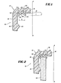
- FIG. 1 A portion of a closure cap 10 of a unitary two-shot design is illustrated in Fig. 1. It includes a substantially rigid outer closure member 12 comprising an annular side wall 14 and a transverse top wall 16. The outside surface of the side wall 14 is provided with serrations 18 which extend outwardly from-the outside surface to provide a gripping-surface for ease of torque application. The inside surface of the side wall 14 is provided with a thread 20.
- the closure cap 10 also includes an annular sealing member 22 which is secured to the transverse top wall 16 by an arrangement of outwardly extending ribs 24, 26 and 28, referred to collectively as the anchor.
- the sealing member 22 also includes a base portion 30 from which the ribs 24, 26 and 28 extend, and from which two transversely spaced sealing flanges 32 and 34 also extend, but in an opposite direction to that of the ribs 24, 26 and 28.
- the base portion 30 defines a merger region 36 which provides a bridge between the flanges 32 and 34.
- the outer flange 32 is spaced from the side wall 14 a distance sufficient to prevent contact there between when the cap has been applied to a container.
- the flanges 32 and 34 are so angled and the distance between them is such that the flanges will engage only the rim edges and the top surface of the wall of a container to which the cap is applied.
- the sealing member 22 serves the same purpose as do the sealing members disclosed.in the previously noted patent 4,308,965, except that the sealing member 22 constructed in accordance with the present invention provides the cap 10 with an enhanced sealing capability.
- the outer closure member 12 was increased in size to accommodate the container.
- the diameter of the sealing member 22 was correspondingly increased but the dimensions a, b and c (Fig. 1) remained constant as it was believed that a good sealing capacity could be achieved with these dimensions held constant.
- the closure member 12 was made of polypropylene while the sealing member 22 was made of a thermoplastic rubber material.
- the closure cap diameters reflect the diameter ranges of the openings of a majority of the containers on the market. These ranges represent container families in which the design characteristics are similar; e.g. wall thickness.
- the dimension a represents the transverse distance between the inner facing edges of the flanges 32 and 34, while the dimension b represents the longitudinal (i.e. in the direction along axis A-A) thickness of the base portion 30 (first longitudinal thickness) and the dimension c represents the longitudinal thickness of the base portion 30 of either of the flanges 32 or 34 (second longitudinal thickness).
- b is no greater than approximately 50% of a and is no greater than approximately 65% of c. It is preferred that c is no greater than approximately 75% of a.
- the Shore A hardness is approximately a linear function of each dimensional group with b being no greater than approximately 40% of a for a Shore A-hardness of less than 55, b being no greater than approximately 30% of a, and no greater than approximately 60% of c for a Shore A hardness of less than 50. It was furthermore observed that the-Shore A hardness was reduced by approximately 10% between the various ranges noted and that this decrease had the effect of increasing the dimension a by 7-8%, and decreasing b by 15-20% and c by 10-15% between the various ranges.
- Exemplary embodiments of closure caps have been manufactured and the following additional data is given by way of example only.
- plastics material for the outer closure member 12 both polypropylene and polyethylene have proved suitable.
- plastics material for the sealing member 22 low density polyethylene and thermoplastic rubber have proved suitable.
- Concerning the dimensions of the sealing member 22, the Table above gives exemplary dimensions for closure caps having a range of diameters.
- dimensions for other parameters of these caps are as follows. Typically, the width of each flange at its free or lower end (as seen in Fig. 1) is 20x10 -3 in. (.051x10 -2 m.) and the lateral spacing between the flanges 32, 34 at base portion 30 is 40x10 -3 in.
- the pair of surfaces of flange 32, 34, which contact the container wall 38, are inclined to the vertical by an angle of approximately 45°.
- the ribs 24, 28 extend at an angle of approximately 45 0 from the vertical and extend to a height measured from the base portion of 30x10 -3 in. (.076x10 2 m.), these ribs having a typical width of 25x10 -3 in. (.064x10 -2 m.). These values are typical across the range of closure caps given in the Table.
- a closure cap with an outer closure member 12 and sealing member 22 can be made by well-known techniques of two-shot injection moulding. Any further discussion of these techniques should be unnecessary to the skilled person in the art.
Landscapes
- Engineering & Computer Science (AREA)
- Mechanical Engineering (AREA)
- Closures For Containers (AREA)
- Finger-Pressure Massage (AREA)
- Transmission Of Braking Force In Braking Systems (AREA)
- Medical Preparation Storing Or Oral Administration Devices (AREA)
Applications Claiming Priority (2)
| Application Number | Priority Date | Filing Date | Title |
|---|---|---|---|
| US06/485,533 US4461393A (en) | 1983-04-15 | 1983-04-15 | Closure cap |
| US485533 | 1995-06-07 |
Publications (2)
| Publication Number | Publication Date |
|---|---|
| EP0122754A2 true EP0122754A2 (de) | 1984-10-24 |
| EP0122754A3 EP0122754A3 (de) | 1985-10-30 |
Family
ID=23928528
Family Applications (1)
| Application Number | Title | Priority Date | Filing Date |
|---|---|---|---|
| EP84302326A Withdrawn EP0122754A3 (de) | 1983-04-15 | 1984-04-05 | Verschulsskappe |
Country Status (10)
| Country | Link |
|---|---|
| US (1) | US4461393A (de) |
| EP (1) | EP0122754A3 (de) |
| JP (1) | JPS59199454A (de) |
| AU (1) | AU2683084A (de) |
| CA (1) | CA1242414A (de) |
| DK (1) | DK191084A (de) |
| ES (1) | ES287006Y (de) |
| FI (1) | FI841499L (de) |
| NO (1) | NO155094C (de) |
| NZ (1) | NZ207827A (de) |
Families Citing this family (21)
| Publication number | Priority date | Publication date | Assignee | Title |
|---|---|---|---|---|
| US5108013A (en) * | 1984-04-16 | 1992-04-28 | Risdon Corporation | Pump for dispensing liquid from a container |
| US4683016A (en) * | 1985-09-03 | 1987-07-28 | Sun Coast Plastics, Inc. | Process for forming a two part closure |
| JPH01103559U (de) * | 1987-12-29 | 1989-07-13 | ||
| GB2231863A (en) * | 1989-04-13 | 1990-11-28 | Dixon Scient Limited | A container |
| JPH07112869B2 (ja) * | 1991-05-23 | 1995-12-06 | 東洋製罐株式会社 | 容器蓋 |
| FR2686065B1 (fr) * | 1992-01-14 | 1994-05-13 | Sincoplas | Dispositif d'obturation de flacon avec joint d'etancheite. |
| DE29514035U1 (de) * | 1995-09-01 | 1996-01-04 | Tonne, Kurt, 27211 Bassum | Behälter, insbesondere Reststoffaß |
| EP0931728A1 (de) * | 1998-01-27 | 1999-07-28 | Rical | Schraubkappe zum Schliessen eines Behälterhalses |
| US6760986B1 (en) * | 2002-05-17 | 2004-07-13 | Macneil David F. | Vehicle license plate cover |
| US20040188375A1 (en) * | 2002-07-03 | 2004-09-30 | Fabricas Monterrey, S.A. De C.V. | Linerless plastic closure with a sealing lip |
| US20040011759A1 (en) * | 2002-07-17 | 2004-01-22 | Hahn John J. | Grip cap |
| WO2005012770A2 (en) * | 2003-07-28 | 2005-02-10 | Gary Englund | Shaped sealing gasket |
| US7690527B2 (en) * | 2003-07-28 | 2010-04-06 | Gary Englund | Shaped sealing gasket |
| FR2865198B1 (fr) * | 2004-01-16 | 2006-04-14 | Valois Sas | Dispositif de distribution de produit fluide |
| US20050189355A1 (en) * | 2004-03-01 | 2005-09-01 | Masterchem Industries, Inc. | Container cap |
| US8006856B2 (en) * | 2004-06-11 | 2011-08-30 | Surpass Industry Co., Ltd. | Seal ring for plug |
| EP2502838B1 (de) * | 2010-07-19 | 2013-12-25 | Red Bull GmbH | Dichtungskonstruktion, insbesondere für wiederverschließbaren Gebindedeckel, wiederverschließbarer Gebindedeckel, enthaltend diese Dichtungskonstruktion, sowie Gebinde, enthaltend diesen Gebindedeckel |
| US9650179B2 (en) * | 2011-12-15 | 2017-05-16 | Proseries Llc | Cap with overmolded gasket anchoring system |
| DE102014211265A1 (de) * | 2014-06-12 | 2015-12-17 | Ball Europe Gmbh | Wiederverschließbarer Aufreißdeckel |
| DE102016223043A1 (de) * | 2016-11-22 | 2018-05-24 | Henkel Ag & Co. Kgaa | Behälter mit Aufsatz |
| US10633150B2 (en) * | 2017-12-04 | 2020-04-28 | Bucktap Llc | Pour spout device |
Family Cites Families (4)
| Publication number | Priority date | Publication date | Assignee | Title |
|---|---|---|---|---|
| US3473683A (en) * | 1968-08-06 | 1969-10-21 | Continental Can Co | Closure with molded ring gasket |
| US4143785A (en) * | 1978-03-16 | 1979-03-13 | Sun Coast Plastic Closures, Inc. | Plastic vacuum sealing cap |
| US4308965A (en) * | 1979-10-24 | 1982-01-05 | Sun Coast Plastic Closures, Inc. | Unitary cap of two dissimilar materials |
| JPS5924943B2 (ja) * | 1981-07-15 | 1984-06-13 | 日本クラウンコルク株式会社 | 内面塗装金属製容器蓋 |
-
1983
- 1983-04-15 US US06/485,533 patent/US4461393A/en not_active Expired - Lifetime
-
1984
- 1984-02-22 JP JP59030469A patent/JPS59199454A/ja active Pending
- 1984-04-05 EP EP84302326A patent/EP0122754A3/de not_active Withdrawn
- 1984-04-11 NO NO841445A patent/NO155094C/no unknown
- 1984-04-12 NZ NZ207827A patent/NZ207827A/en unknown
- 1984-04-13 DK DK191084A patent/DK191084A/da not_active Application Discontinuation
- 1984-04-13 ES ES1984287006U patent/ES287006Y/es not_active Expired
- 1984-04-13 CA CA000451937A patent/CA1242414A/en not_active Expired
- 1984-04-13 AU AU26830/84A patent/AU2683084A/en not_active Abandoned
- 1984-04-13 FI FI841499A patent/FI841499L/fi not_active Application Discontinuation
Also Published As
| Publication number | Publication date |
|---|---|
| ES287006U (es) | 1985-11-16 |
| US4461393A (en) | 1984-07-24 |
| NZ207827A (en) | 1987-08-31 |
| FI841499A7 (fi) | 1984-10-16 |
| FI841499A0 (fi) | 1984-04-13 |
| EP0122754A3 (de) | 1985-10-30 |
| DK191084D0 (da) | 1984-04-13 |
| NO155094C (no) | 1987-02-11 |
| NO155094B (no) | 1986-11-03 |
| AU2683084A (en) | 1984-10-18 |
| JPS59199454A (ja) | 1984-11-12 |
| FI841499L (fi) | 1984-10-16 |
| DK191084A (da) | 1984-10-16 |
| NO841445L (no) | 1984-10-16 |
| ES287006Y (es) | 1986-06-16 |
| CA1242414A (en) | 1988-09-27 |
Similar Documents
| Publication | Publication Date | Title |
|---|---|---|
| EP0122754A2 (de) | Verschulsskappe | |
| US3203571A (en) | Self sealing cap construction | |
| US4564117A (en) | Bottle closure | |
| US3568871A (en) | Closure cap | |
| PL172757B1 (pl) | Zakretka do pojemników, zwlaszcza do butelek PL PL PL PL PL PL | |
| AU666358B2 (en) | Venting closure | |
| US3343700A (en) | Bottle stopper | |
| CA1163234A (en) | Container-closure arrangement | |
| US4721221A (en) | Molded plastic closure with sealing liner | |
| CA1286252C (en) | Linerless closure | |
| EP0140655A2 (de) | Einteiliger Kunststoffverschluss | |
| GB2126567A (en) | Improvements in or relating to closures for containers | |
| US4593408A (en) | Easy open/reclose device for flexible packages | |
| NZ201612A (en) | Thermoplastics closure;liner rotatable until tightened to container | |
| US6044994A (en) | Sealing arrangement for closure caps having liners | |
| EP0136088B1 (de) | Behälterverschluss | |
| US3053406A (en) | Screw cap | |
| US3272369A (en) | Container closure | |
| US4726484A (en) | Package employing unique closure seal and container therefor | |
| EP0036256A1 (de) | Verschlusskappe | |
| US4526284A (en) | Plastic closure with sealing fin | |
| GB2222821A (en) | Closures for releasably sealing containers | |
| US4448319A (en) | Screw cap | |
| EP0391941B1 (de) | Verfahren und einrichtung zum verschliessen von behältern | |
| US3567016A (en) | Container and closure therefor |
Legal Events
| Date | Code | Title | Description |
|---|---|---|---|
| PUAI | Public reference made under article 153(3) epc to a published international application that has entered the european phase |
Free format text: ORIGINAL CODE: 0009012 |
|
| AK | Designated contracting states |
Designated state(s): AT BE CH DE FR GB IT LI LU NL SE |
|
| PUAL | Search report despatched |
Free format text: ORIGINAL CODE: 0009013 |
|
| AK | Designated contracting states |
Designated state(s): AT BE CH DE FR GB IT LI LU NL SE |
|
| 17P | Request for examination filed |
Effective date: 19860217 |
|
| 17Q | First examination report despatched |
Effective date: 19860917 |
|
| STAA | Information on the status of an ep patent application or granted ep patent |
Free format text: STATUS: THE APPLICATION IS DEEMED TO BE WITHDRAWN |
|
| 18D | Application deemed to be withdrawn |
Effective date: 19871222 |
|
| RIN1 | Information on inventor provided before grant (corrected) |
Inventor name: DUTT, HERBERT V. |