EP0120593B1 - Systèmes de régulation électro-pneumatiques - Google Patents
Systèmes de régulation électro-pneumatiques Download PDFInfo
- Publication number
- EP0120593B1 EP0120593B1 EP84301085A EP84301085A EP0120593B1 EP 0120593 B1 EP0120593 B1 EP 0120593B1 EP 84301085 A EP84301085 A EP 84301085A EP 84301085 A EP84301085 A EP 84301085A EP 0120593 B1 EP0120593 B1 EP 0120593B1
- Authority
- EP
- European Patent Office
- Prior art keywords
- signal
- motor
- pneumatic
- control system
- pneumatic output
- Prior art date
- Legal status (The legal status is an assumption and is not a legal conclusion. Google has not performed a legal analysis and makes no representation as to the accuracy of the status listed.)
- Expired
Links
Images

Classifications
-
- G—PHYSICS
- G05—CONTROLLING; REGULATING
- G05D—SYSTEMS FOR CONTROLLING OR REGULATING NON-ELECTRIC VARIABLES
- G05D16/00—Control of fluid pressure
- G05D16/20—Control of fluid pressure characterised by the use of electric means
-
- G—PHYSICS
- G05—CONTROLLING; REGULATING
- G05D—SYSTEMS FOR CONTROLLING OR REGULATING NON-ELECTRIC VARIABLES
- G05D16/00—Control of fluid pressure
- G05D16/20—Control of fluid pressure characterised by the use of electric means
- G05D16/2006—Control of fluid pressure characterised by the use of electric means with direct action of electric energy on controlling means
- G05D16/2013—Control of fluid pressure characterised by the use of electric means with direct action of electric energy on controlling means using throttling means as controlling means
- G05D16/202—Control of fluid pressure characterised by the use of electric means with direct action of electric energy on controlling means using throttling means as controlling means actuated by an electric motor
-
- Y—GENERAL TAGGING OF NEW TECHNOLOGICAL DEVELOPMENTS; GENERAL TAGGING OF CROSS-SECTIONAL TECHNOLOGIES SPANNING OVER SEVERAL SECTIONS OF THE IPC; TECHNICAL SUBJECTS COVERED BY FORMER USPC CROSS-REFERENCE ART COLLECTIONS [XRACs] AND DIGESTS
- Y10—TECHNICAL SUBJECTS COVERED BY FORMER USPC
- Y10T—TECHNICAL SUBJECTS COVERED BY FORMER US CLASSIFICATION
- Y10T137/00—Fluid handling
- Y10T137/2278—Pressure modulating relays or followers
- Y10T137/2409—With counter-balancing pressure feedback to the modulating device
-
- Y—GENERAL TAGGING OF NEW TECHNOLOGICAL DEVELOPMENTS; GENERAL TAGGING OF CROSS-SECTIONAL TECHNOLOGIES SPANNING OVER SEVERAL SECTIONS OF THE IPC; TECHNICAL SUBJECTS COVERED BY FORMER USPC CROSS-REFERENCE ART COLLECTIONS [XRACs] AND DIGESTS
- Y10—TECHNICAL SUBJECTS COVERED BY FORMER USPC
- Y10T—TECHNICAL SUBJECTS COVERED BY FORMER US CLASSIFICATION
- Y10T137/00—Fluid handling
- Y10T137/7722—Line condition change responsive valves
- Y10T137/7758—Pilot or servo controlled
- Y10T137/7761—Electrically actuated valve
Definitions
- This invention relates to electro-pneumatic control systems and, more particularly, but not exclusively, to the control of electro-pneumatic converters.
- Electro-pneumatic converters are known wherein a 4 to 20 mA electrical signal is used to actuate a solenoid-like motor.
- the 4 to 20 mA electrical signal causes a proportionate displacement in a core of the solenoid-like motor, which displacement is used to control an associated valve producing a pressure change proportional to the motion of the core.
- An example of such a device may be found in US Patent No. US-A-3 334 642 (Borthwick).
- WO 80/01826 discloses a closed loop-electro-pneumatic control system, the system comprising:
- the present invention provides a closed-loop electro-pneumatic control system as just defined, the system being characterised by:
- a preferred embodiment of the present invention described hereinbelow overcomes or at least alleviates the above-mentioned problems of known electro-pneumatic converters by providing an electro-pneumatic converter which is dependent upon a direct current (DC) motor to provide a variable restriction to a pneumatic nozzle, thereby providing a fail-safe device which will maintain the last desired signal to the pneumatic assembly upon a loss of electrical power, and which is insensitive to vibration.
- DC direct current
- the preferred electro-pneumatic converter utilises a DC motor which is driven by a 4 to 20 mA input signal to provide a variable restriction to a pneumatic backpressure device by way of a cam, thus allowing the pneumatic device to produce a 20.7 to 103.4 kPa (3 to 15 Ibf/in 2 or "psi") pneumatic output signal corresponding to the 4 to 20 mA input signal.
- the DC motor rotation is provided by an error signal between a set point signal determined by the 4 to 20 mA electrical input and a feedback signal of the corresponding 20.7 to 103.4 kPa (3 to 15 Ibf/in 2 ) pneumatic output signal as sensed by a pressure transducer.
- the power supply used in producing the error signal is biassed up to a reference voltage around which the error signal is referenced to thereby provide bi-directional DC motor rotation in response to positive voltage signals referenced below or above this reference voltage. More specifically, the power supply has two positive voltage sources with reference to common.
- the preferred electro-pneumatic control system will maintain the last pneumatic output signal upon a loss of electric power, that it is insensitive to vibration of the electric motive means, that it has a biassed power supply that is able to provide bi-directional motor rotation without using a positive and negative voltage, and that the electro-pneumatic converter can operate from a two-wire process control loop (4 to 20 mA) without a power supply of its own.
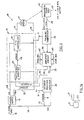
- Figures 1 and 1a show an electro-pneumatic control system 10 wherein a DC motor 12 is controlled by a motor servo circuit 14 which is powered by a power supply 16 operated from a 4 to 20 mA input control signal connected to the power supply 16 along a line 18.
- the DC motor 12 is mechanically constrained to a mechanical servo assembly 20 which has a backpressure nozzle 21 variably restricted by a cam 23 driven by the DC motor 12 to thus provide a variable backpressure output along an output line 22 normally in a 20.7 to 103.4 kPa (3 to 15 Ibf/in 2 ) output range.
- This 20.7 to 103.4 kPa (3 to 15 Ibf/in 2 ) output is linear and corresponds to the linear 4 to 20 mA electrical input provided along the input line 18.
- the same 20.7 to 103.4 kPa (3 to 15 Ibf/in 2 ) output is also sent along a line 24 to a pressure transducer 26 which provides a feedback signal used in determining control of the DC motor 12 as will be described more fully hereinbelow.
- the power supply 16 establishes dual voltages V+ and V, ef along power lines 28 and 30, respectively.
- the V+ voltage is in the range of 6.4 volts nominal and powers the motor servo circuit 14, as well as powering a desired position amplifier 38 and an amplifier circuit 46 along input lines 31 and 33, respectively.
- the V, ef voltage from the power supply 16 is transmitted along the line 30 to bias up the motor servo circuitry 14 and to power the pressure transducer 26 along a line 32.
- the particular electrical input signal is sent along a line 34 to a 10 ohm precision resistor located between the circuit common at a line 36 and an input to the desired position amplifier 38.
- the precision 10 ohm resistor senses the particular current level and establishes a voltage drop across itself. That voltage drop provides a counterpart voltage input to the position amplifier 38.
- the position amplifier 38 raises the input signal level to a predetermined level and sends it along a line 40 to a difference amplifier 42 as a set point signal compatible with the level of a feedback signal also provided to the difference amplifier 42.
- the difference amplifier 42 is the first stage of the motor servo circuit 14.
- the second input to the difference amplifier 42 is the feedback signal, which is provided on a line 44 from the amplifier circuit 46 which scales and zeroes the pressure signal provided by the pressure transducer 26, which acts as a pneumatic-to-electric converter for the 20.7 to 103.4 kPa (3 to 15 Ibf/in 2 ) output signal established at the output line 22.
- the difference amplifier 42 senses any deviation of the feedback signal on the line 44 from the established set point signal on the line 40 and establishes an error signal on a line 48, which error signal is an amplified difference signal so long as such difference between the set point signal and feedback signal is maintained.
- the amplified error signal is supplied to an input of a proportional and integral (P&I) controller 50, where it is integrated and scaled up or down with respect to V ref .
- P&I proportional and integral
- the proportional plus integral controller 50 comprises a pair of driver transistors 52 and 54 in complementary-symmetry configuration, which transistors are respectively NPN and PNP thereby allowing either sourcing or sinking of the current signal to the motor 12 along a line 56.
- the positive terminal of the motor 12 is thus connected to the line 56 while its negative terminal is connected along a line 58 to the voltage reference V, ef on the line 30.
- bi-directional rotation of the motor 12 is achieved by the voltage output of the proportional plus integral controller 50 rising or falling below the voltage reference V ref .
- the NPN transistor 52 of the proportional plus integral controller 50 sources current. This current through the motor 12 will dictate the speed response of the motor 12 with critical damping due to the integral action of the controller 50.
- the voltage differential decreases, the current drawn by the motor 12 and the speed of the motor also decrease.
- the voltage output of the proportional plus integral controller 50 is equal to V rer , no current flows through the motor 12. If the output voltage drops below V ref ., the direction of rotation of the motor will reverse due to the voltage level applied to it crossing the V, sf point. This crossing of the voltage level causes the PNP transistor 54 of the proportional plus integral controller 50 to sink current.
- the amplifier circuit 46 has both a zero adjustment 60 and a span adjustment 62.
- the zero and span adjustments 60 and 62 allow the feedback signal to be adjusted to respond over a variety of ranges.
- the predominant pressure range and pressure starting or zero point that the feedback will be adjusted for is the 20.7 to 103.4 kPa (3 to 15 Ibf/in 2 ) signal, which is a standard for pneumatic instrumentation as 4 to 20 mA is a standard for electrical instrumentation.
- Other ranges are also available and may be set, including any 50 per cent split range desired (i.e. 0 per cent is 20.7 kPa (3 Ibf/in 2 ) and 100 per cent is 62.1 kPa (9 Ibf/in 2 )).
- the DC motor 12 would stop.
- the cam 23 that it drives would remain in its last position providing the same backpressure restriction from the nozzle 21 to the mechanical servo assembly 20 and the last conforming pressure output signal are maintained along the output line 22.
- the motor servo circuit 14 is biassed up by the voltage reference V ref the need for a negative power supply to provide bi-directional rotation of the motor 12 is obviated.
Claims (10)
caractérisé par:
Applications Claiming Priority (2)
| Application Number | Priority Date | Filing Date | Title |
|---|---|---|---|
| US06/468,105 US4509547A (en) | 1983-02-22 | 1983-02-22 | Control system for an electro-pneumatic converter |
| US468105 | 1983-02-22 |
Publications (3)
| Publication Number | Publication Date |
|---|---|
| EP0120593A2 EP0120593A2 (fr) | 1984-10-03 |
| EP0120593A3 EP0120593A3 (en) | 1985-07-10 |
| EP0120593B1 true EP0120593B1 (fr) | 1989-04-19 |
Family
ID=23858446
Family Applications (1)
| Application Number | Title | Priority Date | Filing Date |
|---|---|---|---|
| EP84301085A Expired EP0120593B1 (fr) | 1983-02-22 | 1984-02-20 | Systèmes de régulation électro-pneumatiques |
Country Status (13)
| Country | Link |
|---|---|
| US (1) | US4509547A (fr) |
| EP (1) | EP0120593B1 (fr) |
| JP (2) | JPS59158404A (fr) |
| KR (1) | KR890000611B1 (fr) |
| AU (1) | AU565737B2 (fr) |
| BR (1) | BR8400580A (fr) |
| CA (1) | CA1210477A (fr) |
| DE (1) | DE3477854D1 (fr) |
| ES (1) | ES8500666A1 (fr) |
| HK (1) | HK68789A (fr) |
| IN (1) | IN161518B (fr) |
| MX (1) | MX157424A (fr) |
| SG (1) | SG38989G (fr) |
Families Citing this family (8)
| Publication number | Priority date | Publication date | Assignee | Title |
|---|---|---|---|---|
| US4630631A (en) * | 1983-02-24 | 1986-12-23 | The Babcock & Wilcox Company | Pneumatic servo assembly for an electro-pneumatic converter |
| US4705067A (en) * | 1986-05-13 | 1987-11-10 | Coffee Curtis L | Electric-to-pressure transducer |
| JPH0778691B2 (ja) * | 1986-08-18 | 1995-08-23 | 日本ベ−レ−株式会社 | パルスポジシヨナ |
| GB8811123D0 (en) * | 1988-05-11 | 1988-06-15 | Watson Smith Ltd | Pressure regulator |
| GB9105341D0 (en) * | 1991-03-13 | 1991-04-24 | Watson Smith Ltd | I/p converters |
| US5457435A (en) * | 1994-03-25 | 1995-10-10 | Caterpillar Inc. | Pulse width modulated driver |
| US5642271A (en) * | 1995-08-31 | 1997-06-24 | Hewlett-Packard Company | Pneumatic control system |
| JP5740952B2 (ja) * | 2010-11-04 | 2015-07-01 | 宇部興産株式会社 | 分離膜モジュール |
Family Cites Families (9)
| Publication number | Priority date | Publication date | Assignee | Title |
|---|---|---|---|---|
| BE532990A (fr) * | 1953-11-02 | 1900-01-01 | ||
| US2863287A (en) * | 1956-11-09 | 1958-12-09 | Research Corp | Vacuum control system |
| US3113582A (en) * | 1961-01-11 | 1963-12-10 | Fluidgenics | Pressure control system |
| US3315250A (en) * | 1963-03-29 | 1967-04-18 | Honeywell Inc | Electrical apparatus |
| DE6927354U (de) * | 1968-07-10 | 1972-08-10 | Diesel Kiki Co | Vorrichtung zum umwandeln elektrischer signale in fluddrucksignale. |
| US3819960A (en) * | 1972-05-01 | 1974-06-25 | Love Controls Corp | Controller circuit |
| JPS5519266B2 (fr) * | 1973-03-03 | 1980-05-24 | ||
| US4124811A (en) * | 1977-09-12 | 1978-11-07 | Sperry Rand Corporation | Circuit for bi-directionally powering a motor |
| SE420639B (sv) * | 1979-03-01 | 1981-10-19 | Saab Scania Ab | Signalomvandlare enhet for omvandling av en elektrisk reglersignal till en pneumatisk signal med ett piezoelektrisk element |
-
1983
- 1983-02-22 US US06/468,105 patent/US4509547A/en not_active Expired - Lifetime
-
1984
- 1984-02-01 MX MX200224A patent/MX157424A/es unknown
- 1984-02-10 ES ES529911A patent/ES8500666A1/es not_active Expired
- 1984-02-10 BR BR8400580A patent/BR8400580A/pt not_active IP Right Cessation
- 1984-02-20 CA CA000447859A patent/CA1210477A/fr not_active Expired
- 1984-02-20 DE DE8484301085T patent/DE3477854D1/de not_active Expired
- 1984-02-20 EP EP84301085A patent/EP0120593B1/fr not_active Expired
- 1984-02-21 KR KR1019840000822A patent/KR890000611B1/ko not_active IP Right Cessation
- 1984-02-21 AU AU24789/84A patent/AU565737B2/en not_active Ceased
- 1984-02-21 JP JP59029692A patent/JPS59158404A/ja active Pending
- 1984-02-22 IN IN126/CAL/84A patent/IN161518B/en unknown
-
1989
- 1989-06-24 SG SG389/89A patent/SG38989G/en unknown
- 1989-08-24 HK HK687/89A patent/HK68789A/xx not_active IP Right Cessation
-
1991
- 1991-03-14 JP JP1991022165U patent/JPH04114612U/ja active Pending
Also Published As
| Publication number | Publication date |
|---|---|
| JPS59158404A (ja) | 1984-09-07 |
| ES529911A0 (es) | 1984-11-01 |
| EP0120593A3 (en) | 1985-07-10 |
| AU565737B2 (en) | 1987-09-24 |
| KR890000611B1 (ko) | 1989-03-21 |
| SG38989G (en) | 1990-01-26 |
| US4509547A (en) | 1985-04-09 |
| ES8500666A1 (es) | 1984-11-01 |
| AU2478984A (en) | 1984-08-30 |
| IN161518B (fr) | 1987-12-19 |
| DE3477854D1 (en) | 1989-05-24 |
| KR840009006A (ko) | 1984-12-20 |
| CA1210477A (fr) | 1986-08-26 |
| JPH04114612U (ja) | 1992-10-09 |
| BR8400580A (pt) | 1984-09-25 |
| HK68789A (en) | 1989-09-01 |
| MX157424A (es) | 1988-11-22 |
| EP0120593A2 (fr) | 1984-10-03 |
Similar Documents
| Publication | Publication Date | Title |
|---|---|---|
| US4481967A (en) | Control circuit for current to pressure converter | |
| US4456031A (en) | Electro-hydraulic servo valve system | |
| US5451923A (en) | Communication system and method | |
| EP0120593B1 (fr) | Systèmes de régulation électro-pneumatiques | |
| JPH09512650A (ja) | スマートバルブポジショナ | |
| CA1157928A (fr) | Convertisseur de courant en pression | |
| CA1335116C (fr) | Convertisseur de pression bifilaire a stockage d'energie | |
| US4630631A (en) | Pneumatic servo assembly for an electro-pneumatic converter | |
| EP0174748B1 (fr) | Transmetteurs de position | |
| US4378518A (en) | Rate based autopilot system | |
| EP0120594A2 (fr) | Transducteur electro-pneumatiques | |
| US4901756A (en) | I/P converter with simulated compensation | |
| JP3201555B2 (ja) | バルブポジショナ | |
| JPH0447162B2 (fr) | ||
| JPS6315928Y2 (fr) | ||
| CA1224260A (fr) | Asservissement pneumatique pour convertisseur electro-pneumatique | |
| US2771061A (en) | Latching mechanism for positioning apparatus | |
| CA1152614A (fr) | Circuit de commande pour convertisseur de courant en pression | |
| JPH0534017Y2 (fr) | ||
| JPH0618010B2 (ja) | 自動圧力調節装置 | |
| JPS5810208A (ja) | 流体制御装置 | |
| JPH0298603A (ja) | ポジシヨナ | |
| JPH03186605A (ja) | 電流/圧力変換装置 | |
| JPH10281101A (ja) | 電空変換器 | |
| JPH0447161B2 (fr) |
Legal Events
| Date | Code | Title | Description |
|---|---|---|---|
| PUAI | Public reference made under article 153(3) epc to a published international application that has entered the european phase |
Free format text: ORIGINAL CODE: 0009012 |
|
| AK | Designated contracting states |
Designated state(s): DE FR GB IT |
|
| PUAL | Search report despatched |
Free format text: ORIGINAL CODE: 0009013 |
|
| AK | Designated contracting states |
Designated state(s): DE FR GB IT |
|
| 17P | Request for examination filed |
Effective date: 19851122 |
|
| 17Q | First examination report despatched |
Effective date: 19870713 |
|
| ITF | It: translation for a ep patent filed |
Owner name: ST. ASSOC. MARIETTI & PIPPARELLI |
|
| GRAA | (expected) grant |
Free format text: ORIGINAL CODE: 0009210 |
|
| AK | Designated contracting states |
Kind code of ref document: B1 Designated state(s): DE FR GB IT |
|
| REF | Corresponds to: |
Ref document number: 3477854 Country of ref document: DE Date of ref document: 19890524 |
|
| ET | Fr: translation filed | ||
| PLBE | No opposition filed within time limit |
Free format text: ORIGINAL CODE: 0009261 |
|
| STAA | Information on the status of an ep patent application or granted ep patent |
Free format text: STATUS: NO OPPOSITION FILED WITHIN TIME LIMIT |
|
| 26N | No opposition filed | ||
| REG | Reference to a national code |
Ref country code: GB Ref legal event code: 732 |
|
| ITTA | It: last paid annual fee | ||
| PGFP | Annual fee paid to national office [announced via postgrant information from national office to epo] |
Ref country code: GB Payment date: 19980112 Year of fee payment: 15 |
|
| PGFP | Annual fee paid to national office [announced via postgrant information from national office to epo] |
Ref country code: FR Payment date: 19980116 Year of fee payment: 15 |
|
| PGFP | Annual fee paid to national office [announced via postgrant information from national office to epo] |
Ref country code: DE Payment date: 19980123 Year of fee payment: 15 |
|
| PG25 | Lapsed in a contracting state [announced via postgrant information from national office to epo] |
Ref country code: GB Free format text: LAPSE BECAUSE OF NON-PAYMENT OF DUE FEES Effective date: 19990220 |
|
| GBPC | Gb: european patent ceased through non-payment of renewal fee |
Effective date: 19990220 |
|
| PG25 | Lapsed in a contracting state [announced via postgrant information from national office to epo] |
Ref country code: FR Free format text: LAPSE BECAUSE OF NON-PAYMENT OF DUE FEES Effective date: 19991029 |
|
| PG25 | Lapsed in a contracting state [announced via postgrant information from national office to epo] |
Ref country code: DE Free format text: LAPSE BECAUSE OF NON-PAYMENT OF DUE FEES Effective date: 19991201 |
|
| REG | Reference to a national code |
Ref country code: FR Ref legal event code: ST |