EP0120522A1 - Pumpe mit Druckluftantrieb mit einem Behälter unter Druck für Schmierungssysteme, besonders für Kraftwagen - Google Patents
Pumpe mit Druckluftantrieb mit einem Behälter unter Druck für Schmierungssysteme, besonders für Kraftwagen Download PDFInfo
- Publication number
- EP0120522A1 EP0120522A1 EP84200266A EP84200266A EP0120522A1 EP 0120522 A1 EP0120522 A1 EP 0120522A1 EP 84200266 A EP84200266 A EP 84200266A EP 84200266 A EP84200266 A EP 84200266A EP 0120522 A1 EP0120522 A1 EP 0120522A1
- Authority
- EP
- European Patent Office
- Prior art keywords
- pump
- grease
- reservoir
- way
- valve
- Prior art date
- Legal status (The legal status is an assumption and is not a legal conclusion. Google has not performed a legal analysis and makes no representation as to the accuracy of the status listed.)
- Ceased
Links
- 238000005461 lubrication Methods 0.000 title claims abstract description 9
- 239000004519 grease Substances 0.000 claims abstract description 31
- 239000000314 lubricant Substances 0.000 claims abstract description 9
- 235000014676 Phragmites communis Nutrition 0.000 description 4
- 210000002445 nipple Anatomy 0.000 description 4
- 230000006835 compression Effects 0.000 description 3
- 238000007906 compression Methods 0.000 description 3
- 230000003287 optical effect Effects 0.000 description 3
- 230000000694 effects Effects 0.000 description 2
- 238000005086 pumping Methods 0.000 description 2
- 230000007613 environmental effect Effects 0.000 description 1
- 230000004048 modification Effects 0.000 description 1
- 238000012986 modification Methods 0.000 description 1
Images

Classifications
-
- F—MECHANICAL ENGINEERING; LIGHTING; HEATING; WEAPONS; BLASTING
- F16—ENGINEERING ELEMENTS AND UNITS; GENERAL MEASURES FOR PRODUCING AND MAINTAINING EFFECTIVE FUNCTIONING OF MACHINES OR INSTALLATIONS; THERMAL INSULATION IN GENERAL
- F16N—LUBRICATING
- F16N11/00—Arrangements for supplying grease from a stationary reservoir or the equivalent in or on the machine or member to be lubricated; Grease cups
- F16N11/10—Arrangements for supplying grease from a stationary reservoir or the equivalent in or on the machine or member to be lubricated; Grease cups by pressure of another fluid
-
- F—MECHANICAL ENGINEERING; LIGHTING; HEATING; WEAPONS; BLASTING
- F16—ENGINEERING ELEMENTS AND UNITS; GENERAL MEASURES FOR PRODUCING AND MAINTAINING EFFECTIVE FUNCTIONING OF MACHINES OR INSTALLATIONS; THERMAL INSULATION IN GENERAL
- F16N—LUBRICATING
- F16N13/00—Lubricating-pumps
- F16N13/02—Lubricating-pumps with reciprocating piston
- F16N13/06—Actuation of lubricating-pumps
- F16N13/16—Actuation of lubricating-pumps with fluid drive
Definitions
- This invention relates to a pneumatic pump for lubrication systems, particularly for trucks, trailers, semitrailers and the like.
- the pneumatic pumps currently utilised in the said lubrication systems can be used only with special lubricant greases having a viscosity which can vary only within fairly restricted limits, independently of the wide temperature range of the environment in which the truck or the like operates.
- the lubricant greases used are therefore particularly costly, and are not always easily obtainable, especially in third world countries.
- the object of the present invention is to provide a pneumatic pump for lubrication systems, particularly for trucks, trailers and semitrailers, which is able to operate with common low-cost lubricant greases of almost universal availability, the viscosity of which can vary within fairly wide limits, while ensuring adequate lubrication of the various points to be lubricated, such as leaf springs, steering knuckles etc., under all environmental conditions.
- the pneumatic piston pump is characterised essentially by comprising a differential piston, of which the larger cross-section is acted upon by a pneumatic prsssure, whereas the smaller cross-section acts on the lubricant grease in a chamber which is connected to the points to be lubricated by way of a delivery valve, and to a reservoir - in which the grease is contained under pressure - by way of a suction valve.
- the grease passes from the reservoir, in which it is contained under pressure, through the suction valve and then to the chamber where the smaller cross-section of the differential piston operates, and during the pumping stroke of said piston the grease passes from the chamber to its utilisation points by way of the delivery valve, the suction valve preventing the grease from returning to the reservoir during said compression stage.
- the reservoir can be recharged through an emergency greasing line connected to the reservoir by way of a non-return valve.
- the pump and reservoir constitute one cylindrical body which is divided into two zones by an intermediate element in which the chamber and suction valve are present, said zones being themselves divided into compartments of variable volume by surfaces on which a pneumatic pressure operates, one of which is represented by the larger cross-section of the differential piston and the other by a floating piston which presses against the grease in the reservoir.
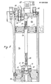
- the reference numeral 1 indicates overall a cylindrical body closed by two end pieces 2, 3 and divided into two zones by a fixed intermediate element 4. Each zone is divided into two compartments of variable volume, indicated by 5a, b and 6a, b respectively, by the surfaces or faces of the floating piston 7 and by those of a differential piston 8, these being guided in a sealed manner in the cylindrical body 1.
- lhe differential piston 8 has one active face which faces the compartment 6a, is loaded by a compression spring 9 which tends to urge it towards the end piece 3, and possesses a stem 10, the front surface 11 of which constitutes the other active face (of much smaller cross-section) of said differential piston 8.
- the stem 10 is disposed slidable in a chamber 12 provided centrally in the intermediate element 4, and constituting the actual pumping chamber of the pump.
- the chamber 12 is connected to a cylindrical space of greater diameter 13 which is connected to a radial duct 15 and to a member 16 screwed into a central bore 17 of the element 4.
- the member 16 which is formed from two or more pieces screwed together, comprises a duct 18 which connects the space 13 to the compartment 5a by way of a valve 19 possessing a valve element 20 loaded by a compression spring 21 which tends to urge it against an internal step 22 of the member 16. More specifically, the valve element is of substantially triangular shape, and (see Figure 2) its dimensions are such as to completely shut off the passage of the grease when it is applied against the step 22.
- a tube 23 Inside which, spaced apart one from the other, there are positioned two proximity switches (reed type) 24, 25, equivalent to two limit switches, which by magnetic action close respective contacts when they are sufficiently closely approached by the floating piston 7, which slides in a sealed manner along said tube 23.
- a permanent magnet 14A In the central part of the piston 7 there is inserted a permanent magnet 14A, which operates the reed switches 24, 25.
- a safety valve 26 which opens when the pressure in the compartment 5b exceeds a predetermined value.
- the compartment 6a is connected to a source of compressed air 33S by way of the pipe 30 and a three-way solenoid valve 32.
- the compartment 5b is also connected to the source 33S by way of a pipe 34 and a non-return valve 36.
- the grease is loaded into the compartment 5a through a line 37, from which a pressure relief valve 42 branches.
- the line 37 comprises a filter 40 to which there are connected both a conventional grease nipple 38 (constituted by a non-return ball valve) to which a normal grease gun 39 present in service stations can be coupled, and to an instant male-female connector 41.
- the lubricant grease can be loaded into the compartment 5a either through the grease nipple 38 or through the connector 41.
- the line 37 is connected by way of a non-return valve 82 to a duct 86 present in the intermediate element 4.
- the duct 15 of said element 4 is connected to an outlet line 50 which by way of a delivery valve 51 leads to the normal lubrication system shown diagrammatically by the distributors 52, the dispensers 53 connected to the preceding, and the lines 54 which lead to the points to be greased.
- a normal grease nipple 55 branches from the line 50, and enables grease to be fed to the utilisation points by means of a normal grease gun 39 should the pneumatic pump not operate, thus enabling the vehicle to be driven to a repair workshop without the danger of damage.
- the three-way solenoid valve 32 is controlled by a timer 60 which is able to connect the operating compartment 6a for a short but predetermined time to the compressed air source 33S (which can be a compressor with its receiver, operated by the vehicle on which the lubrication system is mounted, or alternatively can be the compressed air system already existing on the vehicle).
- the compartment 6a can also be connected to atmosphere for a longer but again predetermined time, by way of the third passage 33A of the valve 32.
- the compartment 5a is filled with grease to a point such that the floating piston 7 is in the position indicated in Figure 1, and that the differential piston 8 is also in the position shown in this figure.
- the timer 60 acts on the valve 32 and connects the compartment 6a to a compressed air source 33S.
- the differential piston 8 then moves in the direction of the arrow Z against the spring 9.
- the air in the compartment 6b leaves through the hole 70.
- the grease contained in the chamber 12 is fed at high pressure into the line 50 and reaches the distributors 52 from which it passes to the dispensers 53 and to the utilisation points through the lines 54.
- the timer 60 then deactivates the valve 32, by which the compartment 6a becomes connected to atmosphere.
- the spring 9 returns the floating piston 8 to the position of Figure 1.
- the valve 19 opens, and a certain quantity of grease under pressure is fed from the compartment 5a to the chamber 12 by the effect of the pressure of the air, which remains pressurised in the chamber 5b.
- the operational cycle is repeated when the timer 60 reactivates the valve 32.
- the grease contained in the compartment 5a is progressively consumed, and when the floating piston 7 causes the minimum-level proximity switch (reed switch) 25 to operate, the contact 25 closes, to allow an acoustic or optical indication to be obtained on the electrical control panel, or to allow some other circuit function to be obtained.
- the floating piston 7 moves to its upper position, ie to the point at which the maximum-level proximity switch (reed switch) 24 is operated, the contact 24 closes to allow an acoustc or optical indication to be obtained on the electrical control panel, or to allow some other circuit function to be obtained.
- the electrical connections are made by a connector 85.
- the loading of the grease into the compartment 5a is obtained without any further or prior manipulation of the compressed air system, in that the air present in the compartment 5b remains at the pressure defined by the safety valve 26, which gradually unloads any pressure excessive to this value as the piston 7 rises and the compartment 5b reduces in volume.
Landscapes
- Engineering & Computer Science (AREA)
- General Engineering & Computer Science (AREA)
- Mechanical Engineering (AREA)
- Details Of Reciprocating Pumps (AREA)
Applications Claiming Priority (2)
| Application Number | Priority Date | Filing Date | Title |
|---|---|---|---|
| IT20120/83A IT1161121B (it) | 1983-03-17 | 1983-03-17 | Pompa ad azionamento pneumatico con serbatoio pressurizzato per impianti di lubrificazione, particolarmente per autotrazione |
| IT2012083 | 1983-03-17 |
Publications (1)
| Publication Number | Publication Date |
|---|---|
| EP0120522A1 true EP0120522A1 (de) | 1984-10-03 |
Family
ID=11163968
Family Applications (1)
| Application Number | Title | Priority Date | Filing Date |
|---|---|---|---|
| EP84200266A Ceased EP0120522A1 (de) | 1983-03-17 | 1984-02-24 | Pumpe mit Druckluftantrieb mit einem Behälter unter Druck für Schmierungssysteme, besonders für Kraftwagen |
Country Status (2)
| Country | Link |
|---|---|
| EP (1) | EP0120522A1 (de) |
| IT (1) | IT1161121B (de) |
Cited By (12)
| Publication number | Priority date | Publication date | Assignee | Title |
|---|---|---|---|---|
| CH666531A5 (en) * | 1985-02-19 | 1988-07-29 | Oerlikon Buehrle Ag | Grease supply for automatic weapon - has gas filled holder to press greasing piston onto grease |
| EP0430024A1 (de) * | 1989-12-01 | 1991-06-05 | Krupp Maschinentechnik Gesellschaft Mit Beschränkter Haftung | Automatische Schmiereinrichtung für den Meissel eines hydraulischen Schlagwerks |
| RU2178860C2 (ru) * | 1997-06-17 | 2002-01-27 | Иркутская государственная сельскохозяйственная академия | Телескопический гидронагнетатель консистентной смазки |
| RU2194209C2 (ru) * | 1998-06-19 | 2002-12-10 | Иркутская государственная сельскохозяйственная академия | Устройство для подачи консистентной смазки |
| US6631787B2 (en) | 1999-12-27 | 2003-10-14 | Lincoln Industrial Corporation | Lubrication system |
| GB2402182A (en) * | 2003-05-29 | 2004-12-01 | Douglas George Anderson | Device for dispensing liquids or flowable solids, eg lubricants, over a lengthy period |
| WO2005036046A1 (de) * | 2003-10-10 | 2005-04-21 | Gesellschaft für technische Entwicklungen mbH | Fett-handling-system |
| EP2039977A3 (de) * | 2007-09-14 | 2011-01-12 | Atlas Copco Construction Tools GmbH | Schmierpumpe |
| WO2015044126A1 (en) | 2013-09-24 | 2015-04-02 | Optimol Tribotechnik S.A. | Metering device for delivery of a liquid or viscous substance |
| RU2576080C1 (ru) * | 2014-11-26 | 2016-02-27 | Общество с ограниченной ответственностью "ПРОСТОР" | Установка для нагнетания смазки |
| IT201600108856A1 (it) * | 2016-10-27 | 2018-04-27 | Dropsa Spa | Pompa pneumatica di lubrificante ad immersione |
| CN116817150A (zh) * | 2023-06-26 | 2023-09-29 | 浙江联众汽车零部件有限公司 | 一种具有自润滑机构的汽车转向节 |
Citations (7)
| Publication number | Priority date | Publication date | Assignee | Title |
|---|---|---|---|---|
| GB191223817A (en) * | 1912-10-18 | 1913-03-20 | Fred Lobnitz | Improvements relating to Centrifugal Pumps. |
| GB299267A (en) * | 1928-04-16 | 1928-10-25 | Erna Conrad | Improvements relating to grease cups |
| US1731159A (en) * | 1929-10-08 | Automatic lubricator | ||
| DE585020C (de) * | 1930-09-03 | 1933-09-28 | Robert Kroesswang | Vorrichtung zum Schmieren von an eine Leitung angeschlossenen Schmierstellen |
| DE742730C (de) * | 1939-04-06 | 1944-01-19 | Siebel Flugzeugwerke G M B H | Vorrichtung zur mechanischen Druckschmierung von Kugellagern vor dem Einbau |
| GB637883A (en) * | 1947-08-08 | 1950-05-31 | Stanley Alban Edward Spinks | Improvements in or relating to apparatus for the delivery of lubricants and the like |
| CH310320A (de) * | 1952-08-15 | 1955-10-15 | Willy Vogel K G Fa | Zentralschmiereinrichtung. |
-
1983
- 1983-03-17 IT IT20120/83A patent/IT1161121B/it active
-
1984
- 1984-02-24 EP EP84200266A patent/EP0120522A1/de not_active Ceased
Patent Citations (7)
| Publication number | Priority date | Publication date | Assignee | Title |
|---|---|---|---|---|
| US1731159A (en) * | 1929-10-08 | Automatic lubricator | ||
| GB191223817A (en) * | 1912-10-18 | 1913-03-20 | Fred Lobnitz | Improvements relating to Centrifugal Pumps. |
| GB299267A (en) * | 1928-04-16 | 1928-10-25 | Erna Conrad | Improvements relating to grease cups |
| DE585020C (de) * | 1930-09-03 | 1933-09-28 | Robert Kroesswang | Vorrichtung zum Schmieren von an eine Leitung angeschlossenen Schmierstellen |
| DE742730C (de) * | 1939-04-06 | 1944-01-19 | Siebel Flugzeugwerke G M B H | Vorrichtung zur mechanischen Druckschmierung von Kugellagern vor dem Einbau |
| GB637883A (en) * | 1947-08-08 | 1950-05-31 | Stanley Alban Edward Spinks | Improvements in or relating to apparatus for the delivery of lubricants and the like |
| CH310320A (de) * | 1952-08-15 | 1955-10-15 | Willy Vogel K G Fa | Zentralschmiereinrichtung. |
Cited By (17)
| Publication number | Priority date | Publication date | Assignee | Title |
|---|---|---|---|---|
| CH666531A5 (en) * | 1985-02-19 | 1988-07-29 | Oerlikon Buehrle Ag | Grease supply for automatic weapon - has gas filled holder to press greasing piston onto grease |
| EP0430024A1 (de) * | 1989-12-01 | 1991-06-05 | Krupp Maschinentechnik Gesellschaft Mit Beschränkter Haftung | Automatische Schmiereinrichtung für den Meissel eines hydraulischen Schlagwerks |
| US5060761A (en) * | 1989-12-01 | 1991-10-29 | Krupp Maschinentechnik Gesellschaft Mit Beschrankter Haftung | Automatic lubricating device for the chisel of a hydraulic striking mechanism |
| RU2178860C2 (ru) * | 1997-06-17 | 2002-01-27 | Иркутская государственная сельскохозяйственная академия | Телескопический гидронагнетатель консистентной смазки |
| RU2194209C2 (ru) * | 1998-06-19 | 2002-12-10 | Иркутская государственная сельскохозяйственная академия | Устройство для подачи консистентной смазки |
| US6631787B2 (en) | 1999-12-27 | 2003-10-14 | Lincoln Industrial Corporation | Lubrication system |
| GB2402182A (en) * | 2003-05-29 | 2004-12-01 | Douglas George Anderson | Device for dispensing liquids or flowable solids, eg lubricants, over a lengthy period |
| WO2005036046A1 (de) * | 2003-10-10 | 2005-04-21 | Gesellschaft für technische Entwicklungen mbH | Fett-handling-system |
| EP2039977A3 (de) * | 2007-09-14 | 2011-01-12 | Atlas Copco Construction Tools GmbH | Schmierpumpe |
| WO2015044126A1 (en) | 2013-09-24 | 2015-04-02 | Optimol Tribotechnik S.A. | Metering device for delivery of a liquid or viscous substance |
| EP3205878A1 (de) | 2013-09-24 | 2017-08-16 | Optimol Tribotechnik S.A. | Dosiervorrichtung zur abgabe einer flüssigkeit oder eines viskosen stoffes |
| RU2576080C1 (ru) * | 2014-11-26 | 2016-02-27 | Общество с ограниченной ответственностью "ПРОСТОР" | Установка для нагнетания смазки |
| IT201600108856A1 (it) * | 2016-10-27 | 2018-04-27 | Dropsa Spa | Pompa pneumatica di lubrificante ad immersione |
| EP3315772A1 (de) * | 2016-10-27 | 2018-05-02 | DROPSA S.p.A. | Pneumatische eintauchschmierstoffpumpe |
| US10533704B2 (en) | 2016-10-27 | 2020-01-14 | Dropsa S.P.A. | Pneumatic immersion lubricant pump |
| CN116817150A (zh) * | 2023-06-26 | 2023-09-29 | 浙江联众汽车零部件有限公司 | 一种具有自润滑机构的汽车转向节 |
| CN116817150B (zh) * | 2023-06-26 | 2024-06-07 | 浙江联众汽车零部件有限公司 | 一种具有自润滑机构的汽车转向节 |
Also Published As
| Publication number | Publication date |
|---|---|
| IT1161121B (it) | 1987-03-11 |
| IT8320120A0 (it) | 1983-03-17 |
Similar Documents
| Publication | Publication Date | Title |
|---|---|---|
| EP0120522A1 (de) | Pumpe mit Druckluftantrieb mit einem Behälter unter Druck für Schmierungssysteme, besonders für Kraftwagen | |
| US3015345A (en) | Combination reservoir-accumulator arrangement for hydraulic system | |
| US6553761B2 (en) | Suspension system for motor vehicles | |
| US4476892A (en) | Dual purpose refrigerant connector | |
| CA2314974A1 (en) | Air dryer reservoir module | |
| US6363719B2 (en) | Hydraulic control unit for a motor vehicle braking system | |
| US5865917A (en) | Deformation-based tire inflation device | |
| JPH03186462A (ja) | アキュムレータ及びこのスイッチング装置 | |
| US4371317A (en) | Hydraulic systems | |
| US2234488A (en) | Compressor unloading valve mechanism | |
| EP0769437A3 (de) | Bremsflüssigkeitsdruck-Steuereinheit | |
| US1987256A (en) | Lubricating mechanism | |
| US3595340A (en) | Lubrication pump | |
| US2987312A (en) | Vehicle suspension system having a pneumatic member and a device for correcting trim | |
| US3473473A (en) | Pump control means | |
| US4520245A (en) | Differential pressure operated electrical switch construction | |
| US1866106A (en) | Lubricant dispensing apparatus | |
| US5188197A (en) | Central-lubrication assembly | |
| US1307734A (en) | Lubricating means | |
| DE3671728D1 (de) | Bremsventil fuer anhaenger-druckluftbremsanlage. | |
| US1955109A (en) | Lubricating apparatus | |
| US3044405A (en) | Fluid pressure generator and accumulator assembly | |
| US1880854A (en) | Lubricating system and apparatus | |
| US4630360A (en) | Method of making differential pressure operated electrical switch | |
| SU1248867A2 (ru) | Регул тор давлени в тормозном приводе транспортного средства |
Legal Events
| Date | Code | Title | Description |
|---|---|---|---|
| PUAI | Public reference made under article 153(3) epc to a published international application that has entered the european phase |
Free format text: ORIGINAL CODE: 0009012 |
|
| AK | Designated contracting states |
Designated state(s): AT BE DE FR GB NL SE |
|
| 17P | Request for examination filed |
Effective date: 19850206 |
|
| 17Q | First examination report despatched |
Effective date: 19860507 |
|
| STAA | Information on the status of an ep patent application or granted ep patent |
Free format text: STATUS: THE APPLICATION HAS BEEN REFUSED |
|
| 18R | Application refused |
Effective date: 19870926 |
|
| RIN1 | Information on inventor provided before grant (corrected) |
Inventor name: GUALTIERO, DIVISI |