EP0120329B1 - Système de balayage électromagnétique - Google Patents
Système de balayage électromagnétique Download PDFInfo
- Publication number
- EP0120329B1 EP0120329B1 EP84102082A EP84102082A EP0120329B1 EP 0120329 B1 EP0120329 B1 EP 0120329B1 EP 84102082 A EP84102082 A EP 84102082A EP 84102082 A EP84102082 A EP 84102082A EP 0120329 B1 EP0120329 B1 EP 0120329B1
- Authority
- EP
- European Patent Office
- Prior art keywords
- beam deflection
- deflection system
- mirror
- motors
- receiver
- Prior art date
- Legal status (The legal status is an assumption and is not a legal conclusion. Google has not performed a legal analysis and makes no representation as to the accuracy of the status listed.)
- Expired
Links
Images


Classifications
-
- G—PHYSICS
- G01—MEASURING; TESTING
- G01B—MEASURING LENGTH, THICKNESS OR SIMILAR LINEAR DIMENSIONS; MEASURING ANGLES; MEASURING AREAS; MEASURING IRREGULARITIES OF SURFACES OR CONTOURS
- G01B11/00—Measuring arrangements characterised by the use of optical techniques
- G01B11/26—Measuring arrangements characterised by the use of optical techniques for measuring angles or tapers; for testing the alignment of axes
- G01B11/275—Measuring arrangements characterised by the use of optical techniques for measuring angles or tapers; for testing the alignment of axes for testing wheel alignment
- G01B11/2755—Measuring arrangements characterised by the use of optical techniques for measuring angles or tapers; for testing the alignment of axes for testing wheel alignment using photoelectric detection means
-
- G—PHYSICS
- G01—MEASURING; TESTING
- G01B—MEASURING LENGTH, THICKNESS OR SIMILAR LINEAR DIMENSIONS; MEASURING ANGLES; MEASURING AREAS; MEASURING IRREGULARITIES OF SURFACES OR CONTOURS
- G01B11/00—Measuring arrangements characterised by the use of optical techniques
- G01B11/002—Measuring arrangements characterised by the use of optical techniques for measuring two or more coordinates
-
- G—PHYSICS
- G01—MEASURING; TESTING
- G01B—MEASURING LENGTH, THICKNESS OR SIMILAR LINEAR DIMENSIONS; MEASURING ANGLES; MEASURING AREAS; MEASURING IRREGULARITIES OF SURFACES OR CONTOURS
- G01B11/00—Measuring arrangements characterised by the use of optical techniques
- G01B11/26—Measuring arrangements characterised by the use of optical techniques for measuring angles or tapers; for testing the alignment of axes
-
- G—PHYSICS
- G01—MEASURING; TESTING
- G01S—RADIO DIRECTION-FINDING; RADIO NAVIGATION; DETERMINING DISTANCE OR VELOCITY BY USE OF RADIO WAVES; LOCATING OR PRESENCE-DETECTING BY USE OF THE REFLECTION OR RERADIATION OF RADIO WAVES; ANALOGOUS ARRANGEMENTS USING OTHER WAVES
- G01S17/00—Systems using the reflection or reradiation of electromagnetic waves other than radio waves, e.g. lidar systems
- G01S17/02—Systems using the reflection of electromagnetic waves other than radio waves
- G01S17/06—Systems determining position data of a target
- G01S17/46—Indirect determination of position data
-
- G—PHYSICS
- G02—OPTICS
- G02B—OPTICAL ELEMENTS, SYSTEMS OR APPARATUS
- G02B26/00—Optical devices or arrangements for the control of light using movable or deformable optical elements
- G02B26/08—Optical devices or arrangements for the control of light using movable or deformable optical elements for controlling the direction of light
- G02B26/10—Scanning systems
-
- G—PHYSICS
- G01—MEASURING; TESTING
- G01B—MEASURING LENGTH, THICKNESS OR SIMILAR LINEAR DIMENSIONS; MEASURING ANGLES; MEASURING AREAS; MEASURING IRREGULARITIES OF SURFACES OR CONTOURS
- G01B2210/00—Aspects not specifically covered by any group under G01B, e.g. of wheel alignment, caliper-like sensors
- G01B2210/10—Wheel alignment
- G01B2210/30—Reference markings, reflector, scale or other passive device
- G01B2210/306—Mirror, prism or other reflector
Definitions
- the invention relates to a beam deflection system according to the type of the independent claim. From the journal Spectrum der psychologist, March 1981, page 117, it is already known to draw circles, ellipses or squares with a laser beam on the canvas using three rotating mirrors attached to motor shafts. Due to the imprecise mounting of the mirrors and the free running of the motors, this arrangement is not suitable for a definitive and reproducible beam scanning.
- the measures listed in the dependent claims allow advantageous further developments and improvements of the beam deflection system specified in the independent claim.
- the mirror bodies as cylinders, on the one hand, a light, defined attachment of the mirrors to the shaft of the motors is possible and, on the other hand, the motor-mirror arrangement can be easily balanced.
- it is expedient if the rays to be received or transmitted strike the mirror at an acute angle, but if possible perpendicularly. Due to the dynamic balancing of the motors with the mirrors attached, the beam deflection system runs smoothly and you get an evenly moving scanning beam.
- a transmitter is required for the beam deflection system, a laser is particularly suitable for this, since its light is particularly easy to bundle.
- the beam deflection system is to be operated with the transmitter and receiver, it is advantageous to mount a semi-transparent mirror between the transmitter and the beam deflection system and to arrange the receiver in the further beam path. This results in a particularly compact structure of the entire beam deflection system.
- counting devices controlled by the receiver can be queried, which contain information about the angular position of the mirrors on the motor axes. With simple calculation steps it is then possible to obtain information about the location of the object to be measured.
- the motors To achieve a synchronized run of the two motors, it is advantageous to operate the motors by a common clock generator, the frequency of which is fed to a divider, the output signals of which control the motor controls.
- This provides particularly simple control of the radiation deflection system.
- it is expedient to arrange converging lenses between the first mirror and the second mirror in the beam path. This suppresses the offset.
- it is expedient to design the beam deflection system to be pivotable about two axes by means of adjusting motors. The adjustment is made depending on the position of the radiating object.
- the beam deflection systems are particularly advantageous for measuring the track and camber of a vehicle and for determining the distance and direction of a radiating object.
- FIG. 1 shows the basic structure of a scanning system
- FIG. 2 shows the structure of the beam deflection system
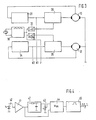
- FIG. 3 shows the control electronics for the motors of the beam deflection system
- FIG. 4 shows a block diagram of the structure of a receiver
- FIG. 5 shows a simple evaluation circuit as a block diagram
- FIG. 6 shows the behavior of the beam on the second mirror
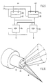
- FIG. 7 a scanning rosette
- FIG. 8 a beam deflection system with inserted lenses
- FIG. 9 an application example of the scanning system according to FIG. 1 for the determination of lane and camber of a motor vehicle
- FIG. 10 an embodiment for using the beam deflection system for object tracking
- FIG Embodiment for locating an object in space shows another embodiment for locating an object in space.
- FIG. 1 shows a scanning system which is suitable for determining the angle of reflecting surfaces.
- a laser beam generator 1 sends its beam through a semi-transparent mirror 2 to the beam deflection system (SAS) 3, from the output of which the deflected beam is thrown onto a reflecting surface 7.
- the reflecting surface 7 is inclined to the vertical of the beam deflection system 3 by the angle ⁇ . Due to the nature of the beam deflection system 3, the emerging beam sweeps every point of the reflecting surface according to a certain system.
- the reflected beam passes through the beam deflection system 3 in the opposite direction. It is deflected at the semi-transparent mirror 2 and, after an aperture 4, hits a receiver 5.
- the receiver 5 sends a signal to the evaluation electronics 6. There, the information about the angular position of the motors of the beam deflection system 3 is evaluated in a computer and the solid angle is calculated and brought to the display.
- the beam deflection system 3 essentially comprises two motors 10 and 12, on the shafts 23, 24 of which cylindrical mirror bodies 11 and 13 are firmly attached.
- the mirror surfaces 21 and 22 of the cylindrical mirror bodies 11 and 13 are chamfered, so that the mirror normals are inclined at an angle a to the axes of rotation of the shafts 23 and 24.
- the angle a is called the wobble angle and is the same for both mirrors.
- the motors 10 and 12 are designed, for example, as DC motors. For speed regulation and as information for the evaluation electronics, the speed and the phase position are measured on each motor.
- the speed and the phase position are measured by means of a fork light barrier 20, into which an aperture 18 protrudes, which is firmly connected to the shaft 24.
- the aperture 18 has a bore 19, so that a pulse is emitted by the fork light barrier 20 when the bore 19 passes the fork light barrier.
- the angle of rotation is detected by means of a reflex light barrier 17 which responds to a marking 25 which is attached to a disk 16 which is fixedly connected to the shaft 23 of the motor.
- the arrangement of the motors is almost arbitrary.
- the rays e.g. B. the incident beam 14, as perpendicular as possible to the reflecting mirror surfaces 21 and 22 of the two mirror bodies 11 and 13.
- the emerging beam is designated 15 in this case.
- each motor with its fixed mirror and any additional masses is dynamically balanced on two levels.
- the wobble angle a of both mirrors be the same so that the scanning beam covers all points of an area.
- FIG. 3 An embodiment of the motor control of the beam deflection system according to Figure 2 is shown in more detail in Figure 3.
- a quartz-controlled clock generator 30 is provided, the output signal of which is supplied to both a divider 32 and a divider 33.
- the divider ratios of the plate 32 and the plate 33 are different.
- the output signal of the divider 32 is supplied as a setpoint to a motor control 36 known per se.
- the motor 10 of the beam deflection system is controlled by the motor control 36.
- a signal for speed detection is tapped from the motor 10 and is fed to the speed evaluation stage 31.
- An amplifier circuit for example, is suitable for this purpose, to the input of which the light barriers described above are connected.
- the speed pulses N1 of the motor 10 are guided to the outside.
- the output of the divider 33 is fed as a setpoint to a speed control 35, the output signal of which determines the speed of the motor 12.
- Speed information is also supplied from the motor 12 to the speed evaluation circuit 34.
- the signal N2 output there is, like the signal N1, available as speed information and as an actual value for the control device 35. Furthermore, the output signal of the clock generator 30 is led to the outside as a reference frequency F.
- the dividers 32 and 33 divide the clock signal in such a way that a speed ratio is established on the motors 10 and 12, which is equal to the ratio of two non-prime integer numbers. If the speed ratio is defined, the reference frequency is divided according to the selected speed ratio. For example, if the reference frequency is 125 kHz and a speed ratio of 1: 1.105 is desired, it is, for example, advantageous to divide by divider 32 by 1000 and by divider 33 by 1105.
- Regulations 35 and 36 continuously compare the divided frequencies obtained from the reference frequency with the recorded speeds and readjust until phase rigidity prevails to the divided reference frequency and thus indirectly via the reference frequency between the two motors.
- FIG. 4 shows a simple evaluation circuit as used in the receiver 5.
- a photodiode 40 or another component sensitive to the radiation used in each case is used to receive the laser beam.
- the signal picked up by the photodiode 40 is amplified by an amplifier 41.
- the subsequent peak hold circuit 42 stores the maximum amplified signal amplitude.
- the output signal is fed to a maximum detection circuit 44.
- the output of the peak value holding circuit 42 is led to a potentiometer 43, from whose tap a further signal for the maximum detection circuit 44 is tapped. This signal ensures that only signals from the photodiode above a fixed, adjustable amplitude level are detected by the maximum voltage circuit 44 are evaluated.
- the decay time constant of the peak value holding circuit 42 is therefore expediently chosen such that the peak value can adapt slowly to signal amplitudes.
- the maximum detection circuit 44 detects the point in time at which a signal whose amplitude is greater than the set threshold reaches its maximum. This can be recognized by simple differentiation, for example. A monoflop 45 is driven with this signal, the positive edge of the generated monoflop pulse corresponding to the time of the maximum. This pulse P is available at the output of the receiver circuit for the evaluation electronics.
- FIG. 1 A simple exemplary embodiment of an evaluation circuit is shown in FIG.
- the reference frequency F derived from the output of the clock generator is fed to the clock input of counters 50 and 51.
- the counter 50 receives a reset pulse from the speed signal N1, which is derived from the speed evaluation circuit 31.
- the counter 51 receives its reset pulse from the speed signal N2, which is derived from the speed evaluation circuit 34.
- a buffer memory 52 is connected to the counter 50.
- a buffer memory 53 is connected to the counter 51.
- the pulse memories P which is emitted by a receiver according to FIG. 4, are fed to the buffer memories 52 and 53 by means of lines.
- the outputs of the buffer memories 52 and 53 are supplied to a ROM 54 and 55, respectively.
- the ROMs 54 and 55 are also activated by the pulse P.
- the vertical angle V can be tapped at the output of the ROM 54 and the horizontal angle H can be tapped at the output of the ROM 55.
- the two counters 50 and 51 which are designed as binary counters, are clocked and counted up by the reference frequency F. After one motor revolution of the corresponding motor of the beam deflection system, they are reset by the corresponding speed pulse. If a pulse P now occurs, which is emitted by the receiver of the scanning system, the current counter readings are temporarily stored in the memories 52 and 53. The temporarily stored counter readings indicate the position of the rotating mirror with respect to one revolution.
- the digital counter readings stored in the memories 52 and 53 are combined to form two correspondingly wide address buses.
- An address bus addresses either ROM 54 or ROM 55, which output the vertical angle V and the horizontal angle H on their data bus. The solid angle of the surface shown in Figure 1 is therefore clearly determined.
- a data word is assigned to each address in ROMs 54 and 55. This in turn corresponds to the vertical angle and the horizontal angle in the other case. This assignment is essentially determined empirically and is dependent on the zero position of the motors, which in turn is determined by the bevelling of the mirror surface in relation to the speed mark. Once this zero position has been determined, the values to be stored in ROMS 54 and 55 can easily be determined empirically depending on the counter reading.
- FIG. 6 shows the behavior of the laser beam on the second mirror 22 in detail.
- the incident beam 14 shown in FIG. 2 hits the mirror 21 first. Since this mirror has a certain inclination, the wobble angle, the mirror normal rotates about the motor axis. Since the incident light beam 14 is spatially fixed, it appears to an observer that the emerging light beam V forms a cone with the tip at the point of incidence of the mirror surface 21 when the mirror 21 rotates quickly enough. The opening angle of the beam cone is four times the wobble angle. This spatially variable beam now reaches the mirror surface 22. Since this mirror surface also has a wobble angle, the mirror here also rotates normally around the motor axis. The emerging beam A is now the beam V reflected on the second mirror. Since the wobble angle is due to the design and is therefore constant, the emerging beam A is only dependent on the respective angle of rotation of the two motors 10 and 12.
- the incident beam V generally describes an oblique projection of a cone, an ellipse, on the mirror surface 22. As a result, the individual rays do not hit the center.
- the emerging beam A is not generated from a point, as was the case with beam V, but has an infinite number of origin points that lie on an ellipse. This phenomenon is called the position offset. If the beam deflection system is only to be used for angle measurement, the offset is irrelevant since the angles of the emerging beams only depend on the angle of inclination of the mirror surface 22 and the angle of rotation of the corresponding motor, but are not dependent on their origin.
- the motors have a speed ratio of - 1: 1.7. This means that the motors 10 and 12 rotate in opposite directions and the motor 12 runs 1.7 times faster than the motor 10.
- the running time which is decisive for the periodicity of the overall figure, depends on the speed ratio. Basically, it can be said that the lower the speed difference between the two motors, the longer the running time.
- the speed ratio n1: n2 must be equal to the ratio of two non-prime integers.
- the speed ratio is also decisive for the sampling density.
- the dissolution behavior is to be influenced by the direction of rotation. A larger resolution in the middle is obtained if the directions of rotation of the two motors are opposite, while the same direction of rotation of the two motors leads to a greater resolution at the edge of the scanning range.
- the aforementioned offset is insignificant in the case of pure angle measurement, it is disruptive if the beam deflection system is to be used as a tracking system or for distance measurement. In this case the offset must be eliminated.
- FIG. 8 the easiest way to do this is with the aid of a lens system.
- the incident beam 14 reaches a mirror 21 which is placed on the cylinder 11.
- the cylinder 11 is driven by the motor 10 via a shaft.
- the emerging beam V of this system arrives at a converging lens 60 and a focusing lens 61, which are aligned in such a way that the beam V falls on the center of the mirror surface 22 which is applied to the cylinder 13.
- the cylinder 13 is driven by the motor 12 via a shaft.
- the emerging beam A is now generated from a point and therefore has no offset.
- FIG. 9 show application examples of the invention.
- the beam deflection system is used for an wheel aligner.
- a vehicle 62 with wheels 63 the lane and the camber are to be determined.
- mirrors 64 are mounted on the wheels of an axle.
- two scanning systems 65 which are constructed in accordance with FIG. 1, are provided. Lines lead from the scanning systems 65 to an evaluation circuit 66.
- the alignment of the scanning systems 65 takes place without a vehicle in between. Alternately, one scanning system is operated only as a transmitter and the other only as a receiver.
- the evaluation position 66 allows the exact position of the two devices to be recognized. These values serve as a reference. For the measurement, the vehicle is moved between the scanning systems 65. By means of the evaluation electronics it is now possible to recognize the deviations with which the reflectors 64 are mounted with respect to the axis of rotation of the wheel 63. To do this, it is necessary to measure the mirror position at at least three wheel angle positions, since then the rotational axis of the wheel axis is clearly determined. These values are saved and taken into account in the subsequent wheel alignment. This enables quick measurements without time-consuming adjustment work.
- the application example according to FIG. 10 shows the use of the beam deflection system as a tracking system.
- the beam deflection system 3 is in this case mounted on a spatially pivotable arrangement 68 which can be driven by motors.
- a receiver 5 is fixedly connected to the beam deflection system.
- the reception pulses of the receiver 5 and the pulses which signal the phase position of the motors are fed to an evaluation circuit 69.
- the evaluation circuit controls the motors of the beam deflection system 3 and the motors of the swivel device 68 as a function of the position of a radiating object 67.
- the beam of the radiating object 67 falls into the beam deflection system 3 at a measurable angle and is detected by the receiver 5 when the motors 10 and 12 of the beam deflection system 3 are in a certain position.
- the solid angles of the radiating object 67 can be clearly determined.
- This angle information is supplied to the control device of the swivel device 68, so that the beam deflection system can be tracked to the radiating object. Since in this case the radiating object is usually to be held in the center of the beam deflection system, it is advantageous if the motors of the beam deflection system rotate in opposite directions.
- FIG. 11 shows an arrangement with which it is possible to determine the distance and the direction of a point-shaped radiating object 67.
- at least two beam deflection systems 3 are provided, each of which is followed by a receiver 5.
- the signals of the receivers 5 are fed to an evaluation circuit.
- the beam deflection systems 3 are controlled in a known manner by the evaluation circuit 70.
- the distance between the beam deflection systems 3 is known and is available to the evaluation circuit.
- Both the first beam deflection system 3 and the second beam deflection system 3 now determine a direction in which the radiating object 67 is located in each case.
- the angular values of the two beam deflection systems and the known distance can be used to determine not only the directions of the radiating object but also its distances from the beam deflection systems.
- FIG. 12 Another possibility for determining the distance and the angle of a radiating object is shown in FIG.
- the arrangement according to FIG. 12 is intended to determine the angle and the distance of a reflecting surface in relation to the beam deflection system 3.
- the beam deflection system 3 there are three receivers 5, the distance between which is defined and to the beam deflection system.
- a transmitter 1 emits a beam which is varied by the beam deflection system 3.
- Three angles can be determined from the three pulses of the receiver 5. Based on known trigonometric formulas, the distance and the angle of the surface can now be calculated by the evaluation circuit 6.
- the invention is not limited to the use of laser beams.
- the specific area can also be scanned by means of light beams, heat rays or microwaves.
- the receivers and transmitters must be selected depending on the specific application.
Landscapes
- Physics & Mathematics (AREA)
- General Physics & Mathematics (AREA)
- Electromagnetism (AREA)
- Engineering & Computer Science (AREA)
- Optics & Photonics (AREA)
- Computer Networks & Wireless Communication (AREA)
- Radar, Positioning & Navigation (AREA)
- Remote Sensing (AREA)
- Length Measuring Devices By Optical Means (AREA)
- Optical Radar Systems And Details Thereof (AREA)
Claims (15)
Applications Claiming Priority (2)
| Application Number | Priority Date | Filing Date | Title |
|---|---|---|---|
| DE3310875 | 1983-03-25 | ||
| DE19833310875 DE3310875A1 (de) | 1983-03-25 | 1983-03-25 | Strahlablenksystem |
Publications (3)
| Publication Number | Publication Date |
|---|---|
| EP0120329A2 EP0120329A2 (fr) | 1984-10-03 |
| EP0120329A3 EP0120329A3 (en) | 1985-01-30 |
| EP0120329B1 true EP0120329B1 (fr) | 1988-05-11 |
Family
ID=6194618
Family Applications (1)
| Application Number | Title | Priority Date | Filing Date |
|---|---|---|---|
| EP84102082A Expired EP0120329B1 (fr) | 1983-03-25 | 1984-02-29 | Système de balayage électromagnétique |
Country Status (2)
| Country | Link |
|---|---|
| EP (1) | EP0120329B1 (fr) |
| DE (2) | DE3310875A1 (fr) |
Cited By (14)
| Publication number | Priority date | Publication date | Assignee | Title |
|---|---|---|---|---|
| GB2172122A (en) * | 1985-03-06 | 1986-09-10 | Ernest Valdur Tomlinson | Rotatable reflectors for directing a beam of light |
| EP0219620A2 (fr) * | 1985-10-24 | 1987-04-29 | Messerschmitt-Bölkow-Blohm Gesellschaft mit beschränkter Haftung | Dispositif de balayage permettant d'obtenir des vitesses de déflexion ultra-rapides |
| EP0235861A1 (fr) * | 1986-03-03 | 1987-09-09 | Koninklijke Philips Electronics N.V. | Dispositif pour détecter un défaut de centrage |
| US4843529A (en) * | 1986-09-19 | 1989-06-27 | Lehigh University | Stage lighting apparatus |
| EP0323026A2 (fr) * | 1987-12-28 | 1989-07-05 | Symbol Technologies, Inc. | Dispositif de balayage optique multidirectionnel |
| EP0327762A2 (fr) * | 1988-02-10 | 1989-08-16 | Milliken Research Corporation | Détecteur de l'angle du poil à velours |
| GB2233784A (en) * | 1989-07-04 | 1991-01-16 | Renishaw Plc | Laser beam deflector comprising two reflectors |
| EP0528552A1 (fr) * | 1991-08-01 | 1993-02-24 | V.L. Churchill Limited | Appareil pour mesurer l'alignement de roues |
| EP0533036A1 (fr) * | 1991-09-20 | 1993-03-24 | Bodenseewerk Gerätetechnik GmbH | Tête chercheuse |
| US5696637A (en) * | 1994-08-08 | 1997-12-09 | Reliance Electric Industrial Company | Apparatus for positioning an optical line of sight within a hemispheric region |
| US5734515A (en) * | 1994-08-08 | 1998-03-31 | Reliance Electric Industrial Company | Apparatus for positioning an optical line of sight within a hemispheric region |
| GB2329724A (en) * | 1997-09-24 | 1999-03-31 | Samsung Electronics Co Ltd | A view selecting apparatus for an X-ray inspection system |
| WO2000071972A1 (fr) * | 1999-05-19 | 2000-11-30 | Gieffe Immobiliare S.N.C. Di Gianfranco Crosta & C. | Mesure des angles de roues utilisant les points de transition de rayons lasers reflechis |
| CN110058405A (zh) * | 2019-04-04 | 2019-07-26 | 中国电子科技集团公司第三十八研究所 | 一种高速旋转偏心光波反射机构 |
Families Citing this family (4)
| Publication number | Priority date | Publication date | Assignee | Title |
|---|---|---|---|---|
| FR2748881A1 (fr) * | 1986-06-17 | 1997-11-21 | Trt Telecom Radio Electr | Dispositif de guidage par faisceau laser effectuant un balayage de l'espace en lissajous |
| DE4434042C2 (de) * | 1994-09-23 | 1997-08-07 | Bosch Gmbh Robert | Anordnung zum berührungslosen Erfassen verkehrsbezogener Daten von Objekten auf einer Fahrbahn |
| DE102006041822A1 (de) * | 2006-09-06 | 2008-03-27 | Beissbarth Gmbh | Verfahren zur Fahrwerksmessung eines Kraftfahrzeugs, Fahrwerksvermessungseinrichtung sowie Kraftfahrzeugprüfstrasse |
| JP6870699B2 (ja) | 2018-05-03 | 2021-05-12 | 株式会社村田製作所 | 拡大された画像領域を備える走査光学デバイス |
Family Cites Families (10)
| Publication number | Priority date | Publication date | Assignee | Title |
|---|---|---|---|---|
| US2975668A (en) * | 1957-07-01 | 1961-03-21 | Lockheed Aircraft Corp | Optical scanning device |
| DE1282675B (de) * | 1967-03-21 | 1968-11-14 | Eltro G M B H & Co Ges Fuer St | Vorrichtung zur sinusfoermigen Ablenkung eines Strahlenbuendels mittels Spiegel |
| US3659142A (en) * | 1970-10-26 | 1972-04-25 | Us Navy | Annular scansion circuit for closed circuit television systems |
| FR2223711B1 (fr) * | 1973-03-30 | 1976-05-21 | Philips Massiot Mat Medic | |
| US3994580A (en) * | 1975-02-24 | 1976-11-30 | Xerox Corporation | Optical system for scanning during reciprocal motion |
| US4039246A (en) * | 1976-01-22 | 1977-08-02 | General Dynamics Corporation | Optical scanning apparatus with two mirrors rotatable about a common axis |
| FR2359556A1 (fr) * | 1976-07-21 | 1978-02-17 | Labo Electronique Physique | Circuit de balayage suivant des figures de lissajous |
| US4270862A (en) * | 1979-01-29 | 1981-06-02 | Sperry Corporation | Magneto-optic light deflector system |
| FR2452724A1 (fr) * | 1979-03-29 | 1980-10-24 | Otan | Appareil de balayage optique |
| IT1156026B (it) * | 1982-05-27 | 1987-01-28 | Fiat Ricerche | Dispositivo di deflessione di un fascio laser per eseguire trattamenti termici superficiali di pezzi scanalati |
-
1983
- 1983-03-25 DE DE19833310875 patent/DE3310875A1/de not_active Withdrawn
-
1984
- 1984-02-29 DE DE8484102082T patent/DE3471176D1/de not_active Expired
- 1984-02-29 EP EP84102082A patent/EP0120329B1/fr not_active Expired
Cited By (20)
| Publication number | Priority date | Publication date | Assignee | Title |
|---|---|---|---|---|
| GB2172122A (en) * | 1985-03-06 | 1986-09-10 | Ernest Valdur Tomlinson | Rotatable reflectors for directing a beam of light |
| EP0219620A2 (fr) * | 1985-10-24 | 1987-04-29 | Messerschmitt-Bölkow-Blohm Gesellschaft mit beschränkter Haftung | Dispositif de balayage permettant d'obtenir des vitesses de déflexion ultra-rapides |
| EP0219620A3 (en) * | 1985-10-24 | 1989-05-10 | Messerschmitt-Bolkow-Blohm Gesellschaft Mit Beschrankter Haftung | Rapid scanning device for the highest deflection velocities |
| EP0235861A1 (fr) * | 1986-03-03 | 1987-09-09 | Koninklijke Philips Electronics N.V. | Dispositif pour détecter un défaut de centrage |
| US4843529A (en) * | 1986-09-19 | 1989-06-27 | Lehigh University | Stage lighting apparatus |
| AU618305B2 (en) * | 1987-12-28 | 1991-12-19 | Symbol Technologies, Inc. | Multi-directional optical scanner |
| EP0323026A3 (fr) * | 1987-12-28 | 1990-02-07 | Symbol Technologies, Inc. | Dispositif de balayage optique multidirectionnel |
| EP0323026A2 (fr) * | 1987-12-28 | 1989-07-05 | Symbol Technologies, Inc. | Dispositif de balayage optique multidirectionnel |
| EP0327762A3 (fr) * | 1988-02-10 | 1990-10-10 | Milliken Research Corporation | Détecteur de l'angle du poil à velours |
| EP0327762A2 (fr) * | 1988-02-10 | 1989-08-16 | Milliken Research Corporation | Détecteur de l'angle du poil à velours |
| GB2233784B (en) * | 1989-07-04 | 1993-08-25 | Renishaw Plc | Beam deflector |
| GB2233784A (en) * | 1989-07-04 | 1991-01-16 | Renishaw Plc | Laser beam deflector comprising two reflectors |
| EP0528552A1 (fr) * | 1991-08-01 | 1993-02-24 | V.L. Churchill Limited | Appareil pour mesurer l'alignement de roues |
| EP0533036A1 (fr) * | 1991-09-20 | 1993-03-24 | Bodenseewerk Gerätetechnik GmbH | Tête chercheuse |
| US5696637A (en) * | 1994-08-08 | 1997-12-09 | Reliance Electric Industrial Company | Apparatus for positioning an optical line of sight within a hemispheric region |
| US5734515A (en) * | 1994-08-08 | 1998-03-31 | Reliance Electric Industrial Company | Apparatus for positioning an optical line of sight within a hemispheric region |
| GB2329724A (en) * | 1997-09-24 | 1999-03-31 | Samsung Electronics Co Ltd | A view selecting apparatus for an X-ray inspection system |
| WO2000071972A1 (fr) * | 1999-05-19 | 2000-11-30 | Gieffe Immobiliare S.N.C. Di Gianfranco Crosta & C. | Mesure des angles de roues utilisant les points de transition de rayons lasers reflechis |
| US6559936B1 (en) | 1999-05-19 | 2003-05-06 | Gieffe Immobiliare S.N.C. Di Gianfranco Crosta & C. | Measuring angles of wheels using transition points of reflected laser lines |
| CN110058405A (zh) * | 2019-04-04 | 2019-07-26 | 中国电子科技集团公司第三十八研究所 | 一种高速旋转偏心光波反射机构 |
Also Published As
| Publication number | Publication date |
|---|---|
| DE3310875A1 (de) | 1984-09-27 |
| EP0120329A3 (en) | 1985-01-30 |
| DE3471176D1 (en) | 1988-06-16 |
| EP0120329A2 (fr) | 1984-10-03 |
Similar Documents
| Publication | Publication Date | Title |
|---|---|---|
| EP0120329B1 (fr) | Système de balayage électromagnétique | |
| DE60132651T2 (de) | Positionsbestimmungssystem | |
| DE19757849C5 (de) | Scanner und Vorrichtung zur optischen Erfassung von Hindernissen, sowie deren Verwendung | |
| DE102010053422B3 (de) | Messung der Positionen von Krümmungsmittelpunkten optischer Flächen eines mehrlinsigen optischen Systems | |
| EP2643660B1 (fr) | Laser rotatif | |
| EP3330741B1 (fr) | Capteur optoélectronique et procédé de détection d'objets dans une zone de détection | |
| CH665715A5 (de) | Verfahren und vorrichtung zur messung der winkelablage eines mit einer zielmarke versehenen objektes. | |
| CH676042A5 (en) | Surveying unit with theodolite and range finder - determines coordinates of target point includes light pulse transmitter and receiver | |
| DE4106572C2 (fr) | ||
| CH626720A5 (fr) | ||
| DE3302948A1 (de) | Beruehrungslose optische abstandsmessung | |
| DE3901040C1 (fr) | ||
| DE4422886C2 (de) | Verfahren und Einrichtung zur optischen Bestimmung räumlicher Positionen einzelner reflektierender Objekte | |
| EP2690398B1 (fr) | Dispositif de détermination de la position d'éléments mécaniques | |
| CH684026A5 (de) | Verfahren zur Messung von relativen Winkeln. | |
| DE4427724C2 (de) | Verfahren und Vorrichtung zum Messen einer winkelabhängigen Größe | |
| DE3601386C1 (en) | Method and device for calibrating optical rangefinders | |
| EP0797108B1 (fr) | Procédé de mesure optique d'angles relatifs | |
| DE3148430C2 (de) | Einrichtung zur Bestimmung und Registrierung der Raumkoordinaten eines freifliegenden Geschosses oder Flugkörpers | |
| DE3233101A1 (de) | Verfahren zur bestimmung des winkels der normalen eines um eine ortsfeste drehachse umlaufenden prueflings und messmaschine zur durchfuehrung des verfahrens | |
| WO1989011630A1 (fr) | Procede et dispositif pour mesurer des surfaces | |
| DE3517044C2 (fr) | ||
| DE102017127479B4 (de) | Optoelektronische Vorrichtung zum Erfassen eines Drehwinkels einer rotierenden Welle | |
| DE3919572C2 (fr) | ||
| DE19725547A1 (de) | Verfahren zur echtzeitnahen Pflanzenerkennung |
Legal Events
| Date | Code | Title | Description |
|---|---|---|---|
| PUAI | Public reference made under article 153(3) epc to a published international application that has entered the european phase |
Free format text: ORIGINAL CODE: 0009012 |
|
| 17P | Request for examination filed |
Effective date: 19840229 |
|
| AK | Designated contracting states |
Designated state(s): CH DE FR GB LI |
|
| PUAL | Search report despatched |
Free format text: ORIGINAL CODE: 0009013 |
|
| AK | Designated contracting states |
Designated state(s): CH DE FR GB LI |
|
| 17Q | First examination report despatched |
Effective date: 19861114 |
|
| GRAA | (expected) grant |
Free format text: ORIGINAL CODE: 0009210 |
|
| AK | Designated contracting states |
Kind code of ref document: B1 Designated state(s): CH DE FR GB LI |
|
| GBT | Gb: translation of ep patent filed (gb section 77(6)(a)/1977) | ||
| REF | Corresponds to: |
Ref document number: 3471176 Country of ref document: DE Date of ref document: 19880616 |
|
| ET | Fr: translation filed | ||
| PLBE | No opposition filed within time limit |
Free format text: ORIGINAL CODE: 0009261 |
|
| STAA | Information on the status of an ep patent application or granted ep patent |
Free format text: STATUS: NO OPPOSITION FILED WITHIN TIME LIMIT |
|
| 26N | No opposition filed | ||
| PGFP | Annual fee paid to national office [announced via postgrant information from national office to epo] |
Ref country code: GB Payment date: 19970219 Year of fee payment: 14 |
|
| PGFP | Annual fee paid to national office [announced via postgrant information from national office to epo] |
Ref country code: FR Payment date: 19970221 Year of fee payment: 14 |
|
| PGFP | Annual fee paid to national office [announced via postgrant information from national office to epo] |
Ref country code: CH Payment date: 19970311 Year of fee payment: 14 |
|
| PGFP | Annual fee paid to national office [announced via postgrant information from national office to epo] |
Ref country code: DE Payment date: 19970418 Year of fee payment: 14 |
|
| PG25 | Lapsed in a contracting state [announced via postgrant information from national office to epo] |
Ref country code: LI Free format text: LAPSE BECAUSE OF NON-PAYMENT OF DUE FEES Effective date: 19980228 Ref country code: GB Free format text: LAPSE BECAUSE OF NON-PAYMENT OF DUE FEES Effective date: 19980228 Ref country code: CH Free format text: LAPSE BECAUSE OF NON-PAYMENT OF DUE FEES Effective date: 19980228 Ref country code: FR Free format text: THE PATENT HAS BEEN ANNULLED BY A DECISION OF A NATIONAL AUTHORITY Effective date: 19980228 |
|
| REG | Reference to a national code |
Ref country code: CH Ref legal event code: PL |
|
| GBPC | Gb: european patent ceased through non-payment of renewal fee |
Effective date: 19980228 |
|
| PG25 | Lapsed in a contracting state [announced via postgrant information from national office to epo] |
Ref country code: DE Free format text: LAPSE BECAUSE OF NON-PAYMENT OF DUE FEES Effective date: 19981103 |
|
| REG | Reference to a national code |
Ref country code: FR Ref legal event code: ST |