EP0119631A2 - Dispositif de pulvérisation cathodique magnétron - Google Patents
Dispositif de pulvérisation cathodique magnétron Download PDFInfo
- Publication number
- EP0119631A2 EP0119631A2 EP84103049A EP84103049A EP0119631A2 EP 0119631 A2 EP0119631 A2 EP 0119631A2 EP 84103049 A EP84103049 A EP 84103049A EP 84103049 A EP84103049 A EP 84103049A EP 0119631 A2 EP0119631 A2 EP 0119631A2
- Authority
- EP
- European Patent Office
- Prior art keywords
- cathode
- central
- cathodes
- central cathode
- auxiliary
- Prior art date
- Legal status (The legal status is an assumption and is not a legal conclusion. Google has not performed a legal analysis and makes no representation as to the accuracy of the status listed.)
- Granted
Links
Images

Classifications
-
- C—CHEMISTRY; METALLURGY
- C23—COATING METALLIC MATERIAL; COATING MATERIAL WITH METALLIC MATERIAL; CHEMICAL SURFACE TREATMENT; DIFFUSION TREATMENT OF METALLIC MATERIAL; COATING BY VACUUM EVAPORATION, BY SPUTTERING, BY ION IMPLANTATION OR BY CHEMICAL VAPOUR DEPOSITION, IN GENERAL; INHIBITING CORROSION OF METALLIC MATERIAL OR INCRUSTATION IN GENERAL
- C23C—COATING METALLIC MATERIAL; COATING MATERIAL WITH METALLIC MATERIAL; SURFACE TREATMENT OF METALLIC MATERIAL BY DIFFUSION INTO THE SURFACE, BY CHEMICAL CONVERSION OR SUBSTITUTION; COATING BY VACUUM EVAPORATION, BY SPUTTERING, BY ION IMPLANTATION OR BY CHEMICAL VAPOUR DEPOSITION, IN GENERAL
- C23C14/00—Coating by vacuum evaporation, by sputtering or by ion implantation of the coating forming material
- C23C14/22—Coating by vacuum evaporation, by sputtering or by ion implantation of the coating forming material characterised by the process of coating
- C23C14/34—Sputtering
- C23C14/35—Sputtering by application of a magnetic field, e.g. magnetron sputtering
- C23C14/352—Sputtering by application of a magnetic field, e.g. magnetron sputtering using more than one target
-
- C—CHEMISTRY; METALLURGY
- C23—COATING METALLIC MATERIAL; COATING MATERIAL WITH METALLIC MATERIAL; CHEMICAL SURFACE TREATMENT; DIFFUSION TREATMENT OF METALLIC MATERIAL; COATING BY VACUUM EVAPORATION, BY SPUTTERING, BY ION IMPLANTATION OR BY CHEMICAL VAPOUR DEPOSITION, IN GENERAL; INHIBITING CORROSION OF METALLIC MATERIAL OR INCRUSTATION IN GENERAL
- C23C—COATING METALLIC MATERIAL; COATING MATERIAL WITH METALLIC MATERIAL; SURFACE TREATMENT OF METALLIC MATERIAL BY DIFFUSION INTO THE SURFACE, BY CHEMICAL CONVERSION OR SUBSTITUTION; COATING BY VACUUM EVAPORATION, BY SPUTTERING, BY ION IMPLANTATION OR BY CHEMICAL VAPOUR DEPOSITION, IN GENERAL
- C23C14/00—Coating by vacuum evaporation, by sputtering or by ion implantation of the coating forming material
- C23C14/04—Coating on selected surface areas, e.g. using masks
- C23C14/042—Coating on selected surface areas, e.g. using masks using masks
- C23C14/044—Coating on selected surface areas, e.g. using masks using masks using masks to redistribute rather than totally prevent coating, e.g. producing thickness gradient
-
- C—CHEMISTRY; METALLURGY
- C23—COATING METALLIC MATERIAL; COATING MATERIAL WITH METALLIC MATERIAL; CHEMICAL SURFACE TREATMENT; DIFFUSION TREATMENT OF METALLIC MATERIAL; COATING BY VACUUM EVAPORATION, BY SPUTTERING, BY ION IMPLANTATION OR BY CHEMICAL VAPOUR DEPOSITION, IN GENERAL; INHIBITING CORROSION OF METALLIC MATERIAL OR INCRUSTATION IN GENERAL
- C23C—COATING METALLIC MATERIAL; COATING MATERIAL WITH METALLIC MATERIAL; SURFACE TREATMENT OF METALLIC MATERIAL BY DIFFUSION INTO THE SURFACE, BY CHEMICAL CONVERSION OR SUBSTITUTION; COATING BY VACUUM EVAPORATION, BY SPUTTERING, BY ION IMPLANTATION OR BY CHEMICAL VAPOUR DEPOSITION, IN GENERAL
- C23C14/00—Coating by vacuum evaporation, by sputtering or by ion implantation of the coating forming material
- C23C14/22—Coating by vacuum evaporation, by sputtering or by ion implantation of the coating forming material characterised by the process of coating
- C23C14/50—Substrate holders
- C23C14/505—Substrate holders for rotation of the substrates
-
- H—ELECTRICITY
- H01—ELECTRIC ELEMENTS
- H01J—ELECTRIC DISCHARGE TUBES OR DISCHARGE LAMPS
- H01J37/00—Discharge tubes with provision for introducing objects or material to be exposed to the discharge, e.g. for the purpose of examination or processing thereof
- H01J37/32—Gas-filled discharge tubes
- H01J37/34—Gas-filled discharge tubes operating with cathodic sputtering
- H01J37/3402—Gas-filled discharge tubes operating with cathodic sputtering using supplementary magnetic fields
- H01J37/3405—Magnetron sputtering
Definitions
- the present invention relates broadly to apparatus for cathode sputtering and more particularly to an improved magnetron cathode sputtering apparatus.
- This invention contemplates the provision of a magnetron cathode sputtering system which allows the simultaneous coating of a large number or batch of articles or substrates.
- the system embodies an evacuable coating chamber in which is mounted a central cylindrical cathode and a plurality of auxiliary cylindrical cathodes disposed concentrically around the central cathode.
- Each of said cathodes comprises an elongated tubular target member to the outer surface of which is applied the coating material to be sputtered.
- Magnet assemblies are mounted in each of said cathodes for enhancing the performance thereof and a cooling medium is circulated through the cathodes.
- Each of the cathodes is also rotated, while the magnet assemblies therein remain stationery.
- An article or substrate carrier is mounted between the central cathode and auxiliary cathodes and is caused to revolve around the central cathode in a planetary fashion, while the articles or substrates carried by said carrier are simultaneously rotated whereby to present all surfaces or areas of the articles or substrates to be coated to the coating material sputtered from the cathodes.
- the invention is also concerned with a method of sputter-coating a plurality of articles simultaneously, comprising providing a central elongated cylindrical magnetron cathode and a plurality of auxiliary elongated cylindrical magnetron cathodes in surrounding relation to said central cathode in an evacuable coating chamber, rotating each of said cathodes about its longitudinal axis, supporting a plurality of articles to be coated between said central cathode and said auxiliary cathodes and in spaced relation thereto, rotating said articles, and simultaneously revolving said articles in planetary fashion around said central cathode and past said auxiliary cathodes.
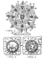
- an evacuable coating chamber 10 composed of an elongated cylindrical wall 11 closed at its opposite ends by the end walls 12 and 13.
- a central cylindrical cathode 14 Mounted centrally within the coating chamber 10 and extending longitudinally thereof is a central cylindrical cathode 14.
- a plurality of auxiliary cylindrical cathodes 15 are also mounted in said coating chamber and are equidistantly positioned around said central cathode 14 in spaced parallel relation thereto.
- the central cathode 14 comprises an elongated tubular target member 16 having a layer 17 of the coating material to be sputtered applied to the outer surface thereof (Fig. 4).
- the tubular member 16 is closed at one end by a cap 18 and is secured at its opposite end to a bearing bracket 19 fastened to the end wall 12 by screws 20.
- O-rings or the like 21 are provided between the meeting faces of the bearing bracket 19 and end wall 12.
- the bearing bracket 19 is provided with a neck portion 22 which passes through an opening in the end wall 12.
- a second tubular member 23 mounted at one end by a trunnion 24 rotatably received in the cap 18 and at its opposite end by a shaft 25 which extends through the bearing bracket 19 and end wall 12 and is surrounded by a seal 26.
- the inner tubular member 23 is driven from a motor 27 carried by end wall 12 through a gear 28 keyed to the motor shaft 29 and meshing with a gear 30 keyed to the end of shaft 25.
- the central cathode 14 is adapted to be internally cooled by circulating a cooling medium, such as water, through the space 31 between the inner tubular member 23 and the outer target member 16.
- a cooling medium such as water
- the cooling medium may be introduced through a pipe 32 extending through the bearing bracket 19 and exit through a pipe 33.
- the central cathode 14 is a magnetron cathode and to this end there is mounted within the inner tubular member 23 a magnet assembly consisting of an array of permanent U-shaped magnets 34. As shown in Fig. 4, the magnets are arranged in four rows a, b, c and d equally spaced around the inner circumference of the tubular member 23 and extending lengthwise thereof. The legs 35 and 36 of the magnets in each row are secured to magnetic strips 37 and 38 respectively by screws 39. The outer surfaces 40 and 41 of the strips 37 and 38 that contact the inner surface of the tubular member 23 are shaped to conform to the curvature thereof. The provision of the magnets enhances the performance of the cathode by increasing the sputter deposition rate.
- Each of the auxiliary cathodes 15 surrounding the central cathode 14 also includes an elongated cylindrical target member 42 having a layer of the coating material 43 to be sputtered applied to the outer surface thereof (Fig. 5).
- Mounted within the tubular member 42 in spaced parallel relation thereto is an inner tubular member.
- the tubular target member 42 is secured at one end to a bearing member 45 and at its opposite end to a similar bearing member 46.
- the bearing members 45 and 46 are provided with extensions 47 and 48 respectively that are rotatably mounted in bearing brackets 49 and 50 respectively secured to the cylindrical wall 11 of the coating chamber.
- the tubular target member 42 of auxiliary cathode 15 is driven from a motor 51 carried by bracket 52 secured to the cylindrical wall 11 of the coating chamber. More specifically, the motor 51 drives a belt 53 which, in turn, drives a pulley 54 keyed to the outer end of a shaft 55 passing through the cylindrical wall 11 and having keyed thereto a worm 56 meshing with worm gear 57 fixed to the extension 47 of bearing member 45.
- Each of the auxiliary cathodes 15 is also adapted to be internally cooled by circulating a cooling medium, such as water, therethrough, said cooling medium being introduced into one end of the cathode through a pipe 59 and exiting at the opposite end through a pipe 60 passing through the bearing members 45 and 46 respectively.
- a cooling medium such as water
- the auxiliary cathodes 15 are also magnetron cathodes and to this end there is mounted in the tubular member 44 of each said cathode a magnet assembly consisting of an array of permanent U-shaped magnets 61 (Fig. 5).
- the magnets 61 are arranged in two rows A and B extending lengthwise of the tubular member.
- the magnets 61 in each row are aligned with one another. with magnets in one row being disposed alternately with and overlapying the magnets in the other row.
- the legs 62 and 63 of the magnets engage and are secured to magnetic strips 64, 65 and 66 by screws 67.
- the outer surfaces 68 of the magnetic strips that engage the inner surface of the tubular member 44 are shaped to conform to the curvature thereof.
- the articles or substrates to be sputter-coated are carried by a rotatable carrier that comprises a plurality of rods 70 on which the articles 71 are held by clamps or the like 72.
- a rotatable carrier that comprises a plurality of rods 70 on which the articles 71 are held by clamps or the like 72.
- One end of each rod 70 is unsupported, while the other end is provided with a collar 73 having a reduced end portion 74 rotatably received in a bushing 75 in a circular carrier plate 76.
- the article support rods 70 extend in spaced parallel relation with the cathodes 14 and 15 and are equidistantly spaced from one another.
- the circular carrier plate 76 is supported axially by a shaft 77 that extends through a bushing 78 in end wall 13 and is surrounded by a seal 79.
- the bushing 78 is provided with an annular flange 80 inwardly of the end wall 13 and posistioned between said flange and end wall are O - rings 81 or other sealing means.
- the shaft 77 projects beyond the bushing 78 and has keyed thereto a gear 82 meshing with a gear 83 keyed to the shaft 84 of motor 85 carried by end wall 13 for rotating the shaft 77 and hence the carrier plate 76.
- each article support rod 70 adjacent the carrier plate 76 Keyed to the end of each article support rod 70 adjacent the carrier plate 76 is a gear 86 meshing with a planetary gear 87 secured to the end wall 13 by screws 88.
- the carrier plate 76 Upon operation of the motor 85 the carrier plate 76 will be rotated to revolve the support rods 70 around the central cathode 14 in planetary fashion, while the support rods themselves will be simultaneously rotated about their axes by rotation of the gears 86 as they travel around the planetary gear 87.
- the articles or substrates to be coated will be both rotated and revolved around the central cathode 14 in such manner as to expose all surfaces or areas to be coated to the coating material sputtered from the cathodes 14 and 15.
- the central cathode and auxiliary cathodes will also be rotated.
- the coating chamber 10 is mounted upon floor supports 89 and 90.
- the end wall 13 of the coating chamber is removably secured to the cylindrical wall 11 by bolts 91 and the support 90 is provided with sleeves 92 and 93 that slide along guide rods 94 which allows the end wall to be moved outwardly upon removal of the bolts 91 to permit access to the interior of the coating chamber for charging or discharging of the articles being processed.
- a cathode potential sufficient to cause sputtering to occur is supplied to the target material 17 of the central cathode 14 from a D.C. power source (not shown) through a power line 95 secured to a contact 96 having sliding engagement with said target material (Fig. 4).
- a similar electrical sliding contact 97 may be associated with each auxiliary cathode 15 (Fig. 5).
- a vacuum pump 98 is provided to evacuate the coating chamber 10 to the desired pressure. Should it be desired to inject gasses into the chamber it may be done through conduit 99 controlled by a valve 100.
Priority Applications (1)
| Application Number | Priority Date | Filing Date | Title |
|---|---|---|---|
| AT84103049T ATE40575T1 (de) | 1983-03-21 | 1984-03-20 | Vorrichtung zur magnetron-kathodenzerstaeubung. |
Applications Claiming Priority (2)
| Application Number | Priority Date | Filing Date | Title |
|---|---|---|---|
| US477069 | 1983-03-21 | ||
| US06/477,069 US4417968A (en) | 1983-03-21 | 1983-03-21 | Magnetron cathode sputtering apparatus |
Publications (3)
| Publication Number | Publication Date |
|---|---|
| EP0119631A2 true EP0119631A2 (fr) | 1984-09-26 |
| EP0119631A3 EP0119631A3 (en) | 1986-03-12 |
| EP0119631B1 EP0119631B1 (fr) | 1989-02-01 |
Family
ID=23894398
Family Applications (1)
| Application Number | Title | Priority Date | Filing Date |
|---|---|---|---|
| EP84103049A Expired EP0119631B1 (fr) | 1983-03-21 | 1984-03-20 | Dispositif de pulvérisation cathodique magnétron |
Country Status (11)
| Country | Link |
|---|---|
| US (1) | US4417968A (fr) |
| EP (1) | EP0119631B1 (fr) |
| JP (1) | JPS59179785A (fr) |
| AT (1) | ATE40575T1 (fr) |
| AU (1) | AU567918B2 (fr) |
| CA (1) | CA1225364A (fr) |
| DE (1) | DE3476563D1 (fr) |
| DK (1) | DK160154C (fr) |
| FI (1) | FI76123C (fr) |
| IT (1) | IT1173906B (fr) |
| NO (1) | NO163414C (fr) |
Cited By (3)
| Publication number | Priority date | Publication date | Assignee | Title |
|---|---|---|---|---|
| EP0214515A2 (fr) * | 1985-09-03 | 1987-03-18 | International Business Machines Corporation | Procédé et appareil pour la formation d'un siliciure métallique |
| WO2011060748A1 (fr) | 2009-11-23 | 2011-05-26 | Shm, S.R.O. | Procédé de création de couches de dépôt physique en phase vapeur à l'aide d'une cathode cylindrique tournante, et appareil pour la mise en œuvre de ce procédé |
| WO2013158067A1 (fr) * | 2012-04-16 | 2013-10-24 | The Timken Company | Procédé et ensemble de table pour appliquer des revêtements à des composants sphériques |
Families Citing this family (52)
| Publication number | Priority date | Publication date | Assignee | Title |
|---|---|---|---|---|
| WO1982002906A1 (fr) * | 1981-02-23 | 1982-09-02 | Leonid Pavlovich Sablev | Cathode consommable pour evaporateur de metal a arc electrique |
| US4443318A (en) * | 1983-08-17 | 1984-04-17 | Shatterproof Glass Corporation | Cathodic sputtering apparatus |
| US4466877A (en) * | 1983-10-11 | 1984-08-21 | Shatterproof Glass Corporation | Magnetron cathode sputtering apparatus |
| KR910000508B1 (ko) * | 1984-08-31 | 1991-01-26 | 니찌덴 아넬바 가부시끼가이샤 | 동적자계를 이용한 방전 반응장치 |
| US4597847A (en) * | 1984-10-09 | 1986-07-01 | Iodep, Inc. | Non-magnetic sputtering target |
| US5215639A (en) * | 1984-10-09 | 1993-06-01 | Genus, Inc. | Composite sputtering target structures and process for producing such structures |
| DE3503398A1 (de) * | 1985-02-01 | 1986-08-07 | W.C. Heraeus Gmbh, 6450 Hanau | Sputteranlage zum reaktiven beschichten eines substrates mit hartstoffen |
| US4701251A (en) * | 1986-02-03 | 1987-10-20 | Bvt Limited | Apparatus for sputter coating discs |
| US4738761A (en) * | 1986-10-06 | 1988-04-19 | Microelectronics Center Of North Carolina | Shared current loop, multiple field apparatus and process for plasma processing |
| US4834860A (en) * | 1987-07-01 | 1989-05-30 | The Boc Group, Inc. | Magnetron sputtering targets |
| US4842703A (en) * | 1988-02-23 | 1989-06-27 | Eaton Corporation | Magnetron cathode and method for sputter coating |
| US5096562A (en) * | 1989-11-08 | 1992-03-17 | The Boc Group, Inc. | Rotating cylindrical magnetron structure for large area coating |
| US5047131A (en) * | 1989-11-08 | 1991-09-10 | The Boc Group, Inc. | Method for coating substrates with silicon based compounds |
| US5045166A (en) * | 1990-05-21 | 1991-09-03 | Mcnc | Magnetron method and apparatus for producing high density ionic gas discharge |
| US5200049A (en) * | 1990-08-10 | 1993-04-06 | Viratec Thin Films, Inc. | Cantilever mount for rotating cylindrical magnetrons |
| US5108574A (en) * | 1991-01-29 | 1992-04-28 | The Boc Group, Inc. | Cylindrical magnetron shield structure |
| CA2108673A1 (fr) * | 1991-04-19 | 1992-10-20 | John Marshall | Methode et appareil de pulverisation magnetron lineaire |
| DE4126236C2 (de) * | 1991-08-08 | 2000-01-05 | Leybold Ag | Rotierende Magnetron-Kathode und Verwendung einer rotierenden Magnetron-Kathode |
| US5338422A (en) * | 1992-09-29 | 1994-08-16 | The Boc Group, Inc. | Device and method for depositing metal oxide films |
| US5286361A (en) * | 1992-10-19 | 1994-02-15 | Regents Of The University Of California | Magnetically attached sputter targets |
| WO1994016118A1 (fr) * | 1993-01-15 | 1994-07-21 | The Boc Group, Inc. | Structure d'ecran cylindrique de magnetron |
| US5414588A (en) * | 1993-09-20 | 1995-05-09 | The Regents Of The University Of California | High performance capacitors using nano-structure multilayer materials fabrication |
| US5571393A (en) * | 1994-08-24 | 1996-11-05 | Viratec Thin Films, Inc. | Magnet housing for a sputtering cathode |
| US5527439A (en) * | 1995-01-23 | 1996-06-18 | The Boc Group, Inc. | Cylindrical magnetron shield structure |
| US5882810A (en) * | 1996-03-08 | 1999-03-16 | The Dow Chemicalcompany | Active layer for membrane electrode assembly |
| US6436252B1 (en) | 2000-04-07 | 2002-08-20 | Surface Engineered Products Corp. | Method and apparatus for magnetron sputtering |
| DE10145201C1 (de) * | 2001-09-13 | 2002-11-21 | Fraunhofer Ges Forschung | Einrichtung zum Beschichten von Substraten mit gekrümmter Oberfläche durch Pulsmagnetron-Zerstäuben |
| DE10221112B4 (de) * | 2002-05-03 | 2008-04-03 | Fhr Anlagenbau Gmbh | Verfahren zur Herstellung eines metallisch glänzenden Schichtsystems auf einem Substrat und Verwendung des Verfahrens |
| US20050224343A1 (en) * | 2004-04-08 | 2005-10-13 | Richard Newcomb | Power coupling for high-power sputtering |
| DE502004010804D1 (de) * | 2004-05-05 | 2010-04-08 | Applied Materials Gmbh & Co Kg | Beschichtungsvorrichtung mit grossflächiger Anordnung von drehbaren Magnetronkathoden |
| US20060065524A1 (en) * | 2004-09-30 | 2006-03-30 | Richard Newcomb | Non-bonded rotatable targets for sputtering |
| US20060096855A1 (en) * | 2004-11-05 | 2006-05-11 | Richard Newcomb | Cathode arrangement for atomizing a rotatable target pipe |
| US20060278521A1 (en) * | 2005-06-14 | 2006-12-14 | Stowell Michael W | System and method for controlling ion density and energy using modulated power signals |
| US20060278524A1 (en) * | 2005-06-14 | 2006-12-14 | Stowell Michael W | System and method for modulating power signals to control sputtering |
| CN101208767B (zh) * | 2005-06-30 | 2012-03-21 | 贝卡尔特先进涂层公司 | 用于单道次涂覆基体两面的组件 |
| US20070089983A1 (en) * | 2005-10-24 | 2007-04-26 | Soleras Ltd. | Cathode incorporating fixed or rotating target in combination with a moving magnet assembly and applications thereof |
| US20070095281A1 (en) * | 2005-11-01 | 2007-05-03 | Stowell Michael W | System and method for power function ramping of microwave liner discharge sources |
| US7842355B2 (en) * | 2005-11-01 | 2010-11-30 | Applied Materials, Inc. | System and method for modulation of power and power related functions of PECVD discharge sources to achieve new film properties |
| US8236152B2 (en) * | 2006-11-24 | 2012-08-07 | Ascentool International Ltd. | Deposition system |
| TWI377264B (en) * | 2007-02-05 | 2012-11-21 | Hon Hai Prec Ind Co Ltd | Sputtering device |
| EP2091067A1 (fr) | 2008-02-14 | 2009-08-19 | Applied Materials, Inc. | Appareil pour le traitement d'un substrat |
| US8083911B2 (en) * | 2008-02-14 | 2011-12-27 | Applied Materials, Inc. | Apparatus for treating a substrate |
| US8182662B2 (en) * | 2009-03-27 | 2012-05-22 | Sputtering Components, Inc. | Rotary cathode for magnetron sputtering apparatus |
| TW201137144A (en) * | 2010-04-29 | 2011-11-01 | Hon Hai Prec Ind Co Ltd | Sputtering device and cleaning method for sputtering target |
| TW201139712A (en) * | 2010-05-12 | 2011-11-16 | Hon Hai Prec Ind Co Ltd | Sputtering device |
| CN102296273B (zh) * | 2010-06-24 | 2013-06-05 | 上海子创镀膜技术有限公司 | 一种真空磁控溅射镀膜用旋转阴极驱动系统 |
| TW201217568A (en) * | 2010-10-26 | 2012-05-01 | Hon Hai Prec Ind Co Ltd | Deposition device |
| TWI480403B (zh) * | 2010-10-26 | 2015-04-11 | Hon Hai Prec Ind Co Ltd | 鍍膜裝置 |
| US20130032476A1 (en) * | 2011-08-04 | 2013-02-07 | Sputtering Components, Inc. | Rotary cathodes for magnetron sputtering system |
| EP2746424B1 (fr) * | 2012-12-21 | 2018-10-17 | Oerlikon Surface Solutions AG, Pfäffikon | Source d'évaporation |
| CN103290382B (zh) * | 2013-05-15 | 2015-09-09 | 宁波韵升股份有限公司 | 一种真空镀膜机行星式工件架 |
| CN112281127A (zh) * | 2020-10-30 | 2021-01-29 | 湘潭宏大真空技术股份有限公司 | 用于磁控溅射镀膜机的承载装置 |
Citations (6)
| Publication number | Priority date | Publication date | Assignee | Title |
|---|---|---|---|---|
| US2476592A (en) * | 1944-12-13 | 1949-07-19 | Fruth Hal Frederick | Cathodic deposition apparatus |
| GB1147318A (en) * | 1968-02-22 | 1969-04-02 | Standard Telephones Cables Ltd | Improvements in r.f. cathodic sputtering systems |
| US3897325A (en) * | 1972-10-20 | 1975-07-29 | Nippon Electric Varian Ltd | Low temperature sputtering device |
| US4126530A (en) * | 1977-08-04 | 1978-11-21 | Telic Corporation | Method and apparatus for sputter cleaning and bias sputtering |
| WO1982002725A1 (fr) * | 1981-02-12 | 1982-08-19 | Glass Corp Shatterproof | Dispositif de bombardement cathodique a magnetron |
| EP0073643A1 (fr) * | 1981-08-27 | 1983-03-09 | Mitsubishi Materials Corporation | Dispositif de pulvérisation |
Family Cites Families (3)
| Publication number | Priority date | Publication date | Assignee | Title |
|---|---|---|---|---|
| JPS49125285A (fr) * | 1973-04-06 | 1974-11-30 | ||
| US3901784A (en) * | 1973-11-15 | 1975-08-26 | United Aircraft Corp | Cylindrical rf sputtering apparatus |
| MX145314A (es) * | 1975-12-17 | 1982-01-27 | Coulter Systems Corp | Mejoras a un aparato chisporroteador para producir pelicula electrofotografica |
-
1983
- 1983-03-21 US US06/477,069 patent/US4417968A/en not_active Expired - Lifetime
-
1984
- 1984-02-24 DK DK098484A patent/DK160154C/da not_active IP Right Cessation
- 1984-02-29 AU AU25156/84A patent/AU567918B2/en not_active Ceased
- 1984-03-16 CA CA000449813A patent/CA1225364A/fr not_active Expired
- 1984-03-20 IT IT20158/84A patent/IT1173906B/it active
- 1984-03-20 DE DE8484103049T patent/DE3476563D1/de not_active Expired
- 1984-03-20 FI FI841119A patent/FI76123C/fi not_active IP Right Cessation
- 1984-03-20 AT AT84103049T patent/ATE40575T1/de active
- 1984-03-20 EP EP84103049A patent/EP0119631B1/fr not_active Expired
- 1984-03-20 NO NO841073A patent/NO163414C/no unknown
- 1984-03-21 JP JP59054136A patent/JPS59179785A/ja active Pending
Patent Citations (6)
| Publication number | Priority date | Publication date | Assignee | Title |
|---|---|---|---|---|
| US2476592A (en) * | 1944-12-13 | 1949-07-19 | Fruth Hal Frederick | Cathodic deposition apparatus |
| GB1147318A (en) * | 1968-02-22 | 1969-04-02 | Standard Telephones Cables Ltd | Improvements in r.f. cathodic sputtering systems |
| US3897325A (en) * | 1972-10-20 | 1975-07-29 | Nippon Electric Varian Ltd | Low temperature sputtering device |
| US4126530A (en) * | 1977-08-04 | 1978-11-21 | Telic Corporation | Method and apparatus for sputter cleaning and bias sputtering |
| WO1982002725A1 (fr) * | 1981-02-12 | 1982-08-19 | Glass Corp Shatterproof | Dispositif de bombardement cathodique a magnetron |
| EP0073643A1 (fr) * | 1981-08-27 | 1983-03-09 | Mitsubishi Materials Corporation | Dispositif de pulvérisation |
Cited By (7)
| Publication number | Priority date | Publication date | Assignee | Title |
|---|---|---|---|---|
| EP0214515A2 (fr) * | 1985-09-03 | 1987-03-18 | International Business Machines Corporation | Procédé et appareil pour la formation d'un siliciure métallique |
| EP0214515A3 (fr) * | 1985-09-03 | 1989-01-11 | International Business Machines Corporation | Procédé et appareil pour la formation d'un siliciure métallique |
| WO2011060748A1 (fr) | 2009-11-23 | 2011-05-26 | Shm, S.R.O. | Procédé de création de couches de dépôt physique en phase vapeur à l'aide d'une cathode cylindrique tournante, et appareil pour la mise en œuvre de ce procédé |
| WO2013158067A1 (fr) * | 2012-04-16 | 2013-10-24 | The Timken Company | Procédé et ensemble de table pour appliquer des revêtements à des composants sphériques |
| CN104379803A (zh) * | 2012-04-16 | 2015-02-25 | 铁姆肯公司 | 用于将涂层施加到球形构件上的方法及工作台组件 |
| CN104379803B (zh) * | 2012-04-16 | 2016-11-09 | 铁姆肯公司 | 用于将涂层施加到球形构件上的方法及工作台组件 |
| US9543127B2 (en) | 2012-04-16 | 2017-01-10 | The Timken Company | Method and table assembly for applying coatings to spherical components |
Also Published As
| Publication number | Publication date |
|---|---|
| FI76123B (fi) | 1988-05-31 |
| AU567918B2 (en) | 1987-12-10 |
| FI76123C (fi) | 1988-09-09 |
| NO841073L (no) | 1984-09-24 |
| FI841119A (fi) | 1984-09-22 |
| DE3476563D1 (de) | 1989-03-09 |
| FI841119A0 (fi) | 1984-03-20 |
| US4417968A (en) | 1983-11-29 |
| IT8420158A0 (it) | 1984-03-20 |
| DK160154B (da) | 1991-02-04 |
| DK160154C (da) | 1991-07-08 |
| CA1225364A (fr) | 1987-08-11 |
| JPS59179785A (ja) | 1984-10-12 |
| EP0119631A3 (en) | 1986-03-12 |
| ATE40575T1 (de) | 1989-02-15 |
| IT1173906B (it) | 1987-06-24 |
| EP0119631B1 (fr) | 1989-02-01 |
| AU2515684A (en) | 1984-09-27 |
| DK98484D0 (da) | 1984-02-24 |
| NO163414C (no) | 1990-05-23 |
| DK98484A (da) | 1984-09-22 |
| NO163414B (no) | 1990-02-12 |
Similar Documents
| Publication | Publication Date | Title |
|---|---|---|
| US4417968A (en) | Magnetron cathode sputtering apparatus | |
| US4422916A (en) | Magnetron cathode sputtering apparatus | |
| EP0070899B1 (fr) | Dispositif de bombardement cathodique a magnetron | |
| US5108574A (en) | Cylindrical magnetron shield structure | |
| US4466877A (en) | Magnetron cathode sputtering apparatus | |
| FI79917C (fi) | Roterbar foerstoftningsanordning och -katod | |
| EP1799876B1 (fr) | Bloc terminal plat comme support pour cible de pulverisation rotative | |
| EP0698908A2 (fr) | Appareil magnétron | |
| US3652444A (en) | Continuous vacuum process apparatus | |
| US5096562A (en) | Rotating cylindrical magnetron structure for large area coating | |
| US5518592A (en) | Seal cartridge for a rotatable magnetron | |
| GB1559269A (en) | Treatment of a workpiece | |
| US4151059A (en) | Method and apparatus for sputtering multiple cylinders simultaneously | |
| EP0550003B1 (fr) | Appareillage de traitement sous vide et ses utilisations | |
| US4701251A (en) | Apparatus for sputter coating discs | |
| US3407783A (en) | Vapor deposition apparatus | |
| US5124013A (en) | High ratio planetary drive system and method for vacuum chamber | |
| KR20000028790A (ko) | 표면처리 지지부재, 표면처리 호울더, 표면처리 방법 및표면처리 장치 | |
| JPH0794711B2 (ja) | イオンプレーティング装置用回転テーブル | |
| US3638927A (en) | Slice conveyor furnace | |
| CA2059094C (fr) | Systeme d'entrainement planetaire a haut rendement pour chambre a vide | |
| US3723276A (en) | Article coating method | |
| CN212199404U (zh) | 一种用于镀膜的公自转镀膜装置 | |
| JPS59144121A (ja) | Cvd装置 | |
| JPH0136910Y2 (fr) |
Legal Events
| Date | Code | Title | Description |
|---|---|---|---|
| PUAI | Public reference made under article 153(3) epc to a published international application that has entered the european phase |
Free format text: ORIGINAL CODE: 0009012 |
|
| AK | Designated contracting states |
Designated state(s): AT BE CH DE FR GB IT LI LU NL SE |
|
| RBV | Designated contracting states (corrected) |
Designated state(s): AT BE CH DE FR GB LI LU NL SE |
|
| PUAL | Search report despatched |
Free format text: ORIGINAL CODE: 0009013 |
|
| AK | Designated contracting states |
Kind code of ref document: A3 Designated state(s): AT BE CH DE FR GB LI LU NL SE |
|
| 17P | Request for examination filed |
Effective date: 19860714 |
|
| 17Q | First examination report despatched |
Effective date: 19880128 |
|
| GRAA | (expected) grant |
Free format text: ORIGINAL CODE: 0009210 |
|
| RAP1 | Party data changed (applicant data changed or rights of an application transferred) |
Owner name: THE BOC GROUP PLC |
|
| AK | Designated contracting states |
Kind code of ref document: B1 Designated state(s): AT BE CH DE FR GB LI LU NL SE |
|
| REF | Corresponds to: |
Ref document number: 40575 Country of ref document: AT Date of ref document: 19890215 Kind code of ref document: T |
|
| REF | Corresponds to: |
Ref document number: 3476563 Country of ref document: DE Date of ref document: 19890309 |
|
| ET | Fr: translation filed | ||
| PLBE | No opposition filed within time limit |
Free format text: ORIGINAL CODE: 0009261 |
|
| STAA | Information on the status of an ep patent application or granted ep patent |
Free format text: STATUS: NO OPPOSITION FILED WITHIN TIME LIMIT |
|
| 26N | No opposition filed | ||
| EPTA | Lu: last paid annual fee | ||
| EAL | Se: european patent in force in sweden |
Ref document number: 84103049.7 |
|
| PGFP | Annual fee paid to national office [announced via postgrant information from national office to epo] |
Ref country code: AT Payment date: 19970217 Year of fee payment: 14 |
|
| PG25 | Lapsed in a contracting state [announced via postgrant information from national office to epo] |
Ref country code: AT Free format text: LAPSE BECAUSE OF NON-PAYMENT OF DUE FEES Effective date: 19980320 |
|
| REG | Reference to a national code |
Ref country code: GB Ref legal event code: IF02 |
|
| PGFP | Annual fee paid to national office [announced via postgrant information from national office to epo] |
Ref country code: FR Payment date: 20020304 Year of fee payment: 19 |
|
| PGFP | Annual fee paid to national office [announced via postgrant information from national office to epo] |
Ref country code: SE Payment date: 20020305 Year of fee payment: 19 Ref country code: NL Payment date: 20020305 Year of fee payment: 19 |
|
| PGFP | Annual fee paid to national office [announced via postgrant information from national office to epo] |
Ref country code: CH Payment date: 20020306 Year of fee payment: 19 |
|
| PGFP | Annual fee paid to national office [announced via postgrant information from national office to epo] |
Ref country code: GB Payment date: 20020313 Year of fee payment: 19 |
|
| PGFP | Annual fee paid to national office [announced via postgrant information from national office to epo] |
Ref country code: LU Payment date: 20020320 Year of fee payment: 19 Ref country code: DE Payment date: 20020320 Year of fee payment: 19 |
|
| PGFP | Annual fee paid to national office [announced via postgrant information from national office to epo] |
Ref country code: BE Payment date: 20020327 Year of fee payment: 19 |
|
| PG25 | Lapsed in a contracting state [announced via postgrant information from national office to epo] |
Ref country code: LU Free format text: LAPSE BECAUSE OF NON-PAYMENT OF DUE FEES Effective date: 20030320 Ref country code: GB Free format text: LAPSE BECAUSE OF NON-PAYMENT OF DUE FEES Effective date: 20030320 |
|
| PG25 | Lapsed in a contracting state [announced via postgrant information from national office to epo] |
Ref country code: SE Free format text: LAPSE BECAUSE OF NON-PAYMENT OF DUE FEES Effective date: 20030321 |
|
| PG25 | Lapsed in a contracting state [announced via postgrant information from national office to epo] |
Ref country code: LI Free format text: LAPSE BECAUSE OF NON-PAYMENT OF DUE FEES Effective date: 20030331 Ref country code: CH Free format text: LAPSE BECAUSE OF NON-PAYMENT OF DUE FEES Effective date: 20030331 Ref country code: BE Free format text: LAPSE BECAUSE OF NON-PAYMENT OF DUE FEES Effective date: 20030331 |
|
| BERE | Be: lapsed |
Owner name: THE *BOC GROUP P.L.C. Effective date: 20030331 |
|
| PG25 | Lapsed in a contracting state [announced via postgrant information from national office to epo] |
Ref country code: NL Free format text: LAPSE BECAUSE OF NON-PAYMENT OF DUE FEES Effective date: 20031001 Ref country code: DE Free format text: LAPSE BECAUSE OF NON-PAYMENT OF DUE FEES Effective date: 20031001 |
|
| EUG | Se: european patent has lapsed | ||
| GBPC | Gb: european patent ceased through non-payment of renewal fee |
Effective date: 20030320 |
|
| REG | Reference to a national code |
Ref country code: CH Ref legal event code: PL |
|
| PG25 | Lapsed in a contracting state [announced via postgrant information from national office to epo] |
Ref country code: FR Free format text: LAPSE BECAUSE OF NON-PAYMENT OF DUE FEES Effective date: 20031127 |
|
| NLV4 | Nl: lapsed or anulled due to non-payment of the annual fee |
Effective date: 20031001 |
|
| REG | Reference to a national code |
Ref country code: FR Ref legal event code: ST |