EP0119362B1 - Koaxiale Resonatoren für gittergesteuerte Röhren - Google Patents
Koaxiale Resonatoren für gittergesteuerte Röhren Download PDFInfo
- Publication number
- EP0119362B1 EP0119362B1 EP83402411A EP83402411A EP0119362B1 EP 0119362 B1 EP0119362 B1 EP 0119362B1 EP 83402411 A EP83402411 A EP 83402411A EP 83402411 A EP83402411 A EP 83402411A EP 0119362 B1 EP0119362 B1 EP 0119362B1
- Authority
- EP
- European Patent Office
- Prior art keywords
- cavities
- tube
- electrodes
- ensuring
- cylinder
- Prior art date
- Legal status (The legal status is an assumption and is not a legal conclusion. Google has not performed a legal analysis and makes no representation as to the accuracy of the status listed.)
- Expired
Links
- 230000008878 coupling Effects 0.000 claims description 19
- 238000010168 coupling process Methods 0.000 claims description 19
- 238000005859 coupling reaction Methods 0.000 claims description 19
- 239000011810 insulating material Substances 0.000 claims description 4
- 239000004642 Polyimide Substances 0.000 claims description 2
- 239000010445 mica Substances 0.000 claims description 2
- 229910052618 mica group Inorganic materials 0.000 claims description 2
- 229920001721 polyimide Polymers 0.000 claims description 2
- -1 polytetra- fluorethylene Polymers 0.000 claims description 2
- 239000003990 capacitor Substances 0.000 description 3
- 230000007423 decrease Effects 0.000 description 3
- 238000006073 displacement reaction Methods 0.000 description 3
- 230000001939 inductive effect Effects 0.000 description 3
- 230000003247 decreasing effect Effects 0.000 description 2
- 210000001015 abdomen Anatomy 0.000 description 1
- 238000009413 insulation Methods 0.000 description 1
- 238000005192 partition Methods 0.000 description 1
- 229920001343 polytetrafluoroethylene Polymers 0.000 description 1
- 239000004810 polytetrafluoroethylene Substances 0.000 description 1
Images
Classifications
-
- H—ELECTRICITY
- H01—ELECTRIC ELEMENTS
- H01P—WAVEGUIDES; RESONATORS, LINES, OR OTHER DEVICES OF THE WAVEGUIDE TYPE
- H01P7/00—Resonators of the waveguide type
- H01P7/04—Coaxial resonators
-
- H—ELECTRICITY
- H01—ELECTRIC ELEMENTS
- H01J—ELECTRIC DISCHARGE TUBES OR DISCHARGE LAMPS
- H01J19/00—Details of vacuum tubes of the types covered by group H01J21/00
- H01J19/78—One or more circuit elements structurally associated with the tube
- H01J19/80—Structurally associated resonator having distributed inductance and capacitance
Definitions
- the present invention relates to resonant coaxial cavities for tube grids.
- These coaxial cavities are coupled on the input or output circuit of grid tubes, such as triodes, tetrodes ..., for example when these tubes are used in the power amplifiers of television transmitters which must respond specific bandwidth specifications.
- a capacitive decoupling is then carried out between these cylinders and two electrodes of the tube so as to isolate the cylinders from the electrodes for direct voltages.
- This capacitive decoupling is generally carried out by an insulating sheet clamped between two cylindrical parts.
- the capacitive decoupling between the cylinders and the electrodes of the tube is carried out at the end of these cylinders located on the side of the tube. Thus all of the cylinders are connected to ground.
- the problem that arises is that for the highest frequencies at which the cavities operate, the piston of the first cavity starting from the tube is located towards the end of the cylinders located on the side of the tube.
- the pistons are arranged at the tension nodes of the standing wave system established in the line, and therefore of course at the current bellies.
- the insulating sheet which makes it possible to carry out the capacitive decoupling between the internal cylinder and one of the electrodes of the tube is therefore located in a high current zone.
- the losses in this dielectric are significant.
- these losses which are troublesome in themselves, cause the temperature to rise in a place which is very difficult to cool.
- the present invention solves this problem.
- the present invention relates to resonant coaxial cavities for grid tube, constituted by a coaxial line separated into several resonant cavities by pistons whose position on the line is adjustable, this line consisting of two coaxial cylinders, connected to ground and provided with means ensuring a capacitive decoupling with two electrodes of the tube.
- the means ensuring the capacitive decoupling of the internal cylinder at one of the electrodes of the tube are arranged in the interval between the positions occupied by the first and the second piston, starting from the tube, for the highest frequency at which operate the cavities.
- this first piston provides a capacitive coupling between the first and the second cavity.
- the means ensuring the capacitive decoupling of the internal cylinder to one of the electrodes of the tube are arranged, from the end of this cylinder located on the side of the tube, substantially at a distance equal to a quarter wave of the highest frequency at which the cavities operate.
- the means ensuring the capacitive decoupling between the internal cylinder and one of the electrodes are therefore moved into an area where, at the highest frequency, the currents are low.
- the preferred position of this decoupling is that where the currents are practically zero, that is to say at a quarter wave of the highest frequency.
- this coupling does not have an optimal position but the currents decreasing strongly when the frequency decreases, the losses are largely reduced.
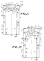
- FIG. 1 represents a view in longitudinal section of a tetrode associated with coaxial cavities according to the prior art.
- the coaxial cavities shown in Figure 1 are coupled by way of example on the output circuit of the tetrode.
- cavities are constituted by a coaxial line 1 comprising an internal cylinder 2 and an external cylinder 3 which are coaxial.
- This coaxial line 1 is separated into several elementary resonant cavities Ci, C 2 , C 3 by pistons P i , P 2 , the position of which on the line is adjustable.
- the pistons are symbolically represented in the figure by a double horizontal arrow. Their possible displacement is indicated by a double vertical arrow.
- the number of cavities and pistons can of course differ from what is shown in FIG. 1.
- a planar capacitor 4 makes it possible to take the energy, in the second cavity in the figure.
- the coupling means between two successive resonant cavities are not shown in FIG. 1. They can be constituted by planar capacitors or for example by the pistons ensuring a capacitive or inductive coupling which have been described in the patent application already cited.
- the first cavity Ci is coupled to the tube and the last cavity C 3 ends in a short circuit.
- the two cylinders 2 and 3 are connected to ground.
- An insulating sheet 5 provides insulation for the DC voltages between the internal cylinder 2 and the grid G 2 .
- This sheet 5 is clamped between the internal cylinder 2 and another cylinder 6 of short length and smaller diameter which is connected to the grid G 2 and which receives by the connection 7 the bias voltage of the grid G 2 , ie V G2 , which is around 1 KV for example.
- the insulating sheet 5 at the end of the internal cylinder 2 on the side of the tube.
- the entire internal cylinder 2 is connected to ground.
- the first piston P l establishes a continuous electrical connection between the two cylinders 2 and 3, it can be displaced over the entire length of the internal cylinder 2 without risk of bringing the entire external cylinder 3 to the DC voltage of the grid G 2 .
- An insulating sheet 5 is also clamped between the external cylinder 3 and another part 8 which is connected to the anode A and which receives by the connection 9 the bias voltage of the anode, ie VA.
- the external cylinder 3 ends in a horizontal ring against which the insulating sheet is pressed which is held by another horizontal ring 8, connected to the anode A and to the connection 9.
- the insulating sheet is pressed vertically at the end of the cylinder 3, outside of the cavity Ci.
- FIG. 2 represents a view in longitudinal section of a tetrode associated with coaxial cavities according to the invention.
- the difference between FIG. 2 and FIG. 1 lies in particular in the position of the means ensuring the capacitive decoupling of the internal cylinder 2 from the grid G 2 .
- these means are arranged from the end of the cylinder situated on the side of the tube, substantially at a distance equal to a quarter wave of the highest frequency at which the cavities operate, ie ⁇ M / 4 this distance.
- the currents are practically zero in the dielectric 5 serving for the coupling of the internal cylinder.
- this coupling does not have an optimal position but the currents decreasing strongly when the frequency decreases, the losses are largely reduced.
- this coupling is placed in the interval, designated by the reference D in FIG. 2, which is between the positions occupied by the first piston P, and the second piston P 2 , starting from the tube, for the highest frequency at which the cavities operate.
- the first piston P l must establish a capacitive coupling between the first and the second cavity. So although the first part 9 of the internal cylinder is not grounded, the entire external cylinder 3 remains grounded which is important for safety reasons.
- the other piston of the line, P 2 can indifferently establish a capacitive or inductive coupling or connect, continuously, the internal cylinder to the external cylinder if the coupling is carried out by a flat capacitor for example.
- the insulating material 5 which is used to carry out the capacitive decoupling between the internal and external cylinders and two electrodes of the tube can be for example made of polytetrafluoroethylene, polyimide or mica.
- Capacitive decoupling can also be achieved by an air gap between these cylinders and the electrodes.
- the cavities according to the invention can be used on the input or output circuit of different grid tubes such as triodes, tetrodes ... They are particularly used on high power tubes, from two kilowatts. They are used for example on tubes operating in UHF between 470 and 850 M Hz.
- the coaxial line is coupled on one side to the anode and on the other hand to the control grid.
- the external cylinder has a greater length than the internal cylinder and that it is therefore possible to place this dielectric in an area where the currents are low for the highest frequency at which the cavities operate, for example, as shown in Figures 1 and 2 at the end of the outer cylinder located on the side of the tube.
Landscapes
- Control Of Motors That Do Not Use Commutators (AREA)
- Rectifiers (AREA)
- Fixed Capacitors And Capacitor Manufacturing Machines (AREA)
Claims (10)
Applications Claiming Priority (2)
| Application Number | Priority Date | Filing Date | Title |
|---|---|---|---|
| FR8221621A FR2538612B1 (fr) | 1982-12-23 | 1982-12-23 | Cavites coaxiales resonnantes pour tubes a grilles |
| FR8221621 | 1982-12-23 |
Publications (2)
| Publication Number | Publication Date |
|---|---|
| EP0119362A1 EP0119362A1 (de) | 1984-09-26 |
| EP0119362B1 true EP0119362B1 (de) | 1987-04-01 |
Family
ID=9280431
Family Applications (1)
| Application Number | Title | Priority Date | Filing Date |
|---|---|---|---|
| EP83402411A Expired EP0119362B1 (de) | 1982-12-23 | 1983-12-13 | Koaxiale Resonatoren für gittergesteuerte Röhren |
Country Status (5)
| Country | Link |
|---|---|
| US (1) | US4571525A (de) |
| EP (1) | EP0119362B1 (de) |
| JP (1) | JPS59132540A (de) |
| DE (1) | DE3370724D1 (de) |
| FR (1) | FR2538612B1 (de) |
Families Citing this family (4)
| Publication number | Priority date | Publication date | Assignee | Title |
|---|---|---|---|---|
| FR2576456B1 (fr) * | 1985-01-22 | 1987-02-06 | Cgr Mev | Generateur d'onde haute frequence |
| FR2655790B1 (fr) * | 1989-12-08 | 1992-01-24 | Thomson Tubes Electroniques | Tube a grille a rendement ameliore. |
| FR2728386B1 (fr) * | 1994-12-20 | 1997-01-24 | Thomson Tubes Electroniques | Tube electronique a grille a performances ameliorees |
| CN115579156B (zh) * | 2022-11-24 | 2023-06-23 | 中国科学院合肥物质科学研究院 | 一种适用于金属陶瓷四极管的调试平台 |
Family Cites Families (10)
| Publication number | Priority date | Publication date | Assignee | Title |
|---|---|---|---|---|
| GB578911A (en) * | 1941-08-26 | 1946-07-17 | Gen Electric Co Ltd | Improvements in electrical apparatus adapted to operate at very high frequencies |
| US2434115A (en) * | 1943-11-26 | 1948-01-06 | Gen Electric | Electric discharge device and coaxial line cavity resonator therefor |
| US2681997A (en) * | 1945-09-14 | 1954-06-22 | Andrew V Haeff | Feedback coupling means |
| US2828438A (en) * | 1947-06-26 | 1958-03-25 | Gen Electric | Electric discharge devices |
| US2642533A (en) * | 1950-07-31 | 1953-06-16 | Eitel Mccullough Inc | Radio-frequency generator |
| DE1000884B (de) * | 1955-10-06 | 1957-01-17 | Telefunken Gmbh | Schwingkreisanordnung fuer grosse Hochfrequenzleistungen |
| US2948858A (en) * | 1958-07-18 | 1960-08-09 | Hughes Aircraft Co | Cavity resonator circuit |
| NL179173C (nl) * | 1976-05-03 | 1986-07-16 | Philips Nv | Versterkerinrichting voor zendtetrode. |
| NL7808556A (nl) * | 1978-08-18 | 1980-02-20 | Philips Nv | Trilholte met verbeterde temperatuursstabiliteit. |
| FR2445037A1 (fr) * | 1978-12-22 | 1980-07-18 | Thomson Csf | Filtre de bande de frequence |
-
1982
- 1982-12-23 FR FR8221621A patent/FR2538612B1/fr not_active Expired
-
1983
- 1983-12-13 DE DE8383402411T patent/DE3370724D1/de not_active Expired
- 1983-12-13 EP EP83402411A patent/EP0119362B1/de not_active Expired
- 1983-12-16 US US06/562,444 patent/US4571525A/en not_active Expired - Lifetime
- 1983-12-22 JP JP58243040A patent/JPS59132540A/ja active Pending
Also Published As
| Publication number | Publication date |
|---|---|
| FR2538612A1 (fr) | 1984-06-29 |
| FR2538612B1 (fr) | 1985-10-04 |
| EP0119362A1 (de) | 1984-09-26 |
| US4571525A (en) | 1986-02-18 |
| JPS59132540A (ja) | 1984-07-30 |
| DE3370724D1 (en) | 1987-05-07 |
Similar Documents
| Publication | Publication Date | Title |
|---|---|---|
| FR2547456A1 (fr) | Tube a faisceau d'electrons module en densite avec un gain accru | |
| EP0381580B1 (de) | Anordnung zur Hochspannungsversorgung einer Röntgenröhre | |
| FR2660796A1 (fr) | Appareil a tube a faisceau electronique comportant une cavite d'entree. | |
| FR2737340A1 (fr) | Tube electronique multifaisceau a couplage cavite/faisceau ameliore | |
| EP0119362B1 (de) | Koaxiale Resonatoren für gittergesteuerte Röhren | |
| EP2472555B1 (de) | Vorrichtung zum Erzeugen von Mikrowellen, die eine Vielzahl von Magnetrons umfasst | |
| FR2760294A1 (fr) | Colonnette d'accord micro-ondes rf a soufflet | |
| EP0718867B1 (de) | Gitterelektronenröhre mit verbesserter Leistung | |
| US2677809A (en) | Electrical wave filter | |
| FR2637731A1 (fr) | Tube a onde progressive muni d'un dispositif de couplage etanche entre sa ligne a retard et un circuit hyperfrequence externe | |
| EP0440530A1 (de) | Hochfrequenzröhre mit mehreren Strahlen und koaxialem Ausgang | |
| FR2471042A1 (fr) | Tube a ondes progressives du type a helice et a large bande passante | |
| EP0013204A1 (de) | Frequenzbandfilter | |
| FR2704092A1 (fr) | Agencement de tube à faisceau électronique. | |
| US2595677A (en) | Electron discharge device | |
| EP0082769A1 (de) | Frequenzvervielfacher | |
| FR2806212A1 (fr) | Agencement de type filtre ou multicoupleur, a resonateur electroniquement accordable | |
| FR2704093A1 (fr) | Tube à faisceau d'électrons linéaire. | |
| WO2009083540A1 (fr) | Protection d'une electrode de tube electronique | |
| WO2009083214A1 (fr) | Accord d'un tube electronique | |
| FR2526232A1 (fr) | Perfectionnements apportes aux cavites resonnantes du type lignes de transmission | |
| CH441448A (fr) | Oscillateur à haute fréquence | |
| FR2466118A1 (fr) | Laser a guide d'ondes a haute frequence | |
| SU313513A1 (ru) | Линейный ускоритель электронов | |
| BE473139A (de) |
Legal Events
| Date | Code | Title | Description |
|---|---|---|---|
| PUAI | Public reference made under article 153(3) epc to a published international application that has entered the european phase |
Free format text: ORIGINAL CODE: 0009012 |
|
| AK | Designated contracting states |
Designated state(s): DE GB IT NL |
|
| 17P | Request for examination filed |
Effective date: 19841004 |
|
| GRAA | (expected) grant |
Free format text: ORIGINAL CODE: 0009210 |
|
| AK | Designated contracting states |
Kind code of ref document: B1 Designated state(s): DE GB IT NL |
|
| ITF | It: translation for a ep patent filed | ||
| REF | Corresponds to: |
Ref document number: 3370724 Country of ref document: DE Date of ref document: 19870507 |
|
| PLBE | No opposition filed within time limit |
Free format text: ORIGINAL CODE: 0009261 |
|
| STAA | Information on the status of an ep patent application or granted ep patent |
Free format text: STATUS: NO OPPOSITION FILED WITHIN TIME LIMIT |
|
| 26N | No opposition filed | ||
| PGFP | Annual fee paid to national office [announced via postgrant information from national office to epo] |
Ref country code: GB Payment date: 19921118 Year of fee payment: 10 |
|
| ITTA | It: last paid annual fee | ||
| PGFP | Annual fee paid to national office [announced via postgrant information from national office to epo] |
Ref country code: NL Payment date: 19921231 Year of fee payment: 10 |
|
| PG25 | Lapsed in a contracting state [announced via postgrant information from national office to epo] |
Ref country code: GB Effective date: 19931213 |
|
| PG25 | Lapsed in a contracting state [announced via postgrant information from national office to epo] |
Ref country code: NL Effective date: 19940701 |
|
| GBPC | Gb: european patent ceased through non-payment of renewal fee |
Effective date: 19931213 |
|
| NLV4 | Nl: lapsed or anulled due to non-payment of the annual fee | ||
| PGFP | Annual fee paid to national office [announced via postgrant information from national office to epo] |
Ref country code: DE Payment date: 20021219 Year of fee payment: 20 |