EP0117977B1 - Probeentnahmegerät für ein Milchmengenmessgerät für Melkanlagen - Google Patents
Probeentnahmegerät für ein Milchmengenmessgerät für Melkanlagen Download PDFInfo
- Publication number
- EP0117977B1 EP0117977B1 EP84100346A EP84100346A EP0117977B1 EP 0117977 B1 EP0117977 B1 EP 0117977B1 EP 84100346 A EP84100346 A EP 84100346A EP 84100346 A EP84100346 A EP 84100346A EP 0117977 B1 EP0117977 B1 EP 0117977B1
- Authority
- EP
- European Patent Office
- Prior art keywords
- sampling device
- milk
- upper portion
- lower portion
- passage
- Prior art date
- Legal status (The legal status is an assumption and is not a legal conclusion. Google has not performed a legal analysis and makes no representation as to the accuracy of the status listed.)
- Expired
Links
- 239000008267 milk Substances 0.000 title claims description 54
- 210000004080 milk Anatomy 0.000 title claims description 54
- 235000013336 milk Nutrition 0.000 title claims description 54
- 238000005070 sampling Methods 0.000 claims description 36
- 239000000725 suspension Substances 0.000 claims description 2
- 238000004891 communication Methods 0.000 claims 1
- 230000000694 effects Effects 0.000 claims 1
- 238000009434 installation Methods 0.000 claims 1
- 238000011017 operating method Methods 0.000 claims 1
- 238000007789 sealing Methods 0.000 claims 1
- 238000000926 separation method Methods 0.000 description 12
- 238000005259 measurement Methods 0.000 description 5
- 238000000034 method Methods 0.000 description 3
- 238000001816 cooling Methods 0.000 description 1
- 239000004615 ingredient Substances 0.000 description 1
- 239000012528 membrane Substances 0.000 description 1
- 239000000203 mixture Substances 0.000 description 1
Images

Classifications
-
- A—HUMAN NECESSITIES
- A01—AGRICULTURE; FORESTRY; ANIMAL HUSBANDRY; HUNTING; TRAPPING; FISHING
- A01J—MANUFACTURE OF DAIRY PRODUCTS
- A01J5/00—Milking machines or devices
- A01J5/04—Milking machines or devices with pneumatic manipulation of teats
- A01J5/045—Taking milk-samples
-
- G—PHYSICS
- G01—MEASURING; TESTING
- G01N—INVESTIGATING OR ANALYSING MATERIALS BY DETERMINING THEIR CHEMICAL OR PHYSICAL PROPERTIES
- G01N1/00—Sampling; Preparing specimens for investigation
- G01N1/02—Devices for withdrawing samples
- G01N1/10—Devices for withdrawing samples in the liquid or fluent state
-
- G—PHYSICS
- G01—MEASURING; TESTING
- G01N—INVESTIGATING OR ANALYSING MATERIALS BY DETERMINING THEIR CHEMICAL OR PHYSICAL PROPERTIES
- G01N33/00—Investigating or analysing materials by specific methods not covered by groups G01N1/00 - G01N31/00
- G01N33/02—Food
- G01N33/04—Dairy products
-
- Y—GENERAL TAGGING OF NEW TECHNOLOGICAL DEVELOPMENTS; GENERAL TAGGING OF CROSS-SECTIONAL TECHNOLOGIES SPANNING OVER SEVERAL SECTIONS OF THE IPC; TECHNICAL SUBJECTS COVERED BY FORMER USPC CROSS-REFERENCE ART COLLECTIONS [XRACs] AND DIGESTS
- Y10—TECHNICAL SUBJECTS COVERED BY FORMER USPC
- Y10T—TECHNICAL SUBJECTS COVERED BY FORMER US CLASSIFICATION
- Y10T137/00—Fluid handling
- Y10T137/8593—Systems
- Y10T137/86493—Multi-way valve unit
- Y10T137/86879—Reciprocating valve unit
Definitions
- the invention relates to a sampling device for a milk quantity measuring device for milking systems, with which partial quantity measurements can be carried out and which has a separation chamber under pressure and a measuring chamber and in which the separation chamber is provided with an outlet opening which can be closed by a valve piston.
- a milk quantity measuring device of the type mentioned is known (DE-OS 31 03 669), in which, with the outlet opening open, the milk flows into a collecting line which is pressurized without sampling being carried out.
- a sampling device for milking systems is known from EP-A-23449, the sample vessel of which is connected to the underside of a separation chamber. Through this connection, milk is only taken from the lower part of the separation chamber for samples. Since the milk in the lower part of the separation chamber contains less fat than the milk in the upper part of the separation chamber, exact sampling cannot be guaranteed.
- the invention has for its object to design a sampling device for a milk quantity measuring device of the type mentioned so that the sampling device does not cause vacuum fluctuations, the partial quantity measurements in the milk quantity measuring device are not influenced and the sample obtained in the collecting vessel is composed of partial milk quantities, the number of which is carried out in the milk quantity measuring device Partial measurements corresponds.
- valve piston assigned to the outlet opening has a nozzle bore open to the separation chamber and a subsequent nozzle channel which is equipped in the region of the end facing away from the nozzle bore with a drain opening which is closed in the closed position of the valve piston and in the open position of the valve piston opens into a line leading to the milk collection chamber of the sampling device.
- a portion is taken from the amount of milk flowing to the collecting line when the outlet opening of the milk quantity measuring device is open, so that the milk entering the milk collecting space of the sampling device is composed of partial amounts distributed over the milking time.
- the milk milked during the first period of milking contains far less fat than the milk obtained in the last period.
- the sampling device ensures that, with a portion of milk measured in portions, a portion corresponding to the size of the portion is taken from each portion. Since the portion size is determined by the opening time of an emptying valve, a proportional portion of the emptied milk quantity is taken as a collective sample during the emptying time.
- the milk in the milk collection chamber of the sampling device must be mixed into the sample bottles before filling so that the ingredients in the milk are evenly distributed.
- the amount of milk located in the milk collecting space of the sampling device can be easily conveyed to the milk already in the cooling tank.
- the vessel having the milk collecting space is provided with a stationary upper part on which a lower part forming the lid of the vessel is rotatably mounted.
- the upper part is equipped with two connecting pieces as well as with at least one control bore and the lower part with at least two channels which can be brought into an aligned position (Meik position) with the connecting pieces.
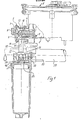
- the milk quantity measuring device 1 shown in FIGS. 1 and 2 is equipped with a separation chamber 2 which is pressurized and to which the milked-air mixture is fed.
- the milk passes from the separation chamber into a measuring chamber in which partial quantity measurements are carried out.
- the milk quantity measuring device is provided with an outlet opening 3 through a valve piston 4 can be closed.
- the valve piston is fastened to a diaphragm 6 clamped in the valve housing 5, which delimits a control chamber 7 on the inside, which can be acted upon by air 8 with atmospheric pressure or with a negative pressure.
- the opening and closing of the outlet opening 3 can be carried out by means of an electronic control device which is connected to sensors which are arranged at a distance from one another in the measuring chamber.
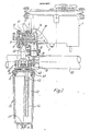
- the valve piston 4 has a nozzle opening 9 which is open to the separation chamber 2 and to which a nozzle channel 10 connects.
- the nozzle channel is provided with a drain opening 11 which is closed in the closed position of the valve piston 4 and opens into a valve chamber 12 under pressure in the open position of the valve piston 4 shown in FIG. 2.
- the valve piston 4 is. in the illustrated embodiment slidably mounted in a sleeve 13 which has a slot-shaped guideway 14 into which a cam 15 of the valve piston 4 engages. As a result, the valve piston is secured against rotation relative to the sleeve 13.
- the sleeve is provided with a slot 16, in the area of which the outlet opening 11 of the nozzle channel 10 lies in the open position of the valve piston 4.
- the valve piston 4 is equipped with an end cap 17, through which the rear opening of the nozzle channel 10 is closed.
- the end cap 17 is attached to the membrane 6.
- the nozzle bore 9 is arranged in a pin 18 projecting from the end face of the valve piston 4 facing the separation chamber 2.
- a milk quantity flows out of the milk quantity measuring device 1 through the line 19 into the collecting line 20 under pressure.
- a partial quantity flows through the nozzle bore 9 into the nozzle channel 10 and reaches the line 21 via the outlet opening 11 and is passed through this line into the milk collecting chamber 22 of the vessel 23 out.
- the vessel 23 is provided with a stationary upper part 24, on which a lower part 25 is rotatably mounted, that forms the lid of the vessel 23 and delimits the milk collecting space 22 at the top.
- the lower part 25 is screwed into an internal thread of the vessel 23 with an external thread 26.
- the pin 27 is designed as a hollow pin and has a socket 29 equipped with an internal thread, into which the threaded shaft 30 of a screw 31 is screwed.
- a cylindrical coil spring 33 is arranged between a washer 32 and the upper part 24. This creates a non-positive connection between the upper part 24 and the lower part 25, a sliding seal being provided between the interacting surfaces of the upper part and the lower part, which can be designed as a disk 48.
- the upper part 24 is equipped with a lateral arm 34, to which a suspension bracket 35 is attached, which is suspended in an annular groove of the valve housing 5.
- An emptying channel 36 is provided in the bottom of the vessel 23, in which a valve body 37 which can be moved into the closed position under the influence of vacuum is slidably mounted.
- the upper part 24 is equipped with two connecting pieces 38, 39 and at least one control bore 40.
- the lower part 25 is provided with at least two channels 41, 42 which can be brought into alignment with the connecting pieces 38, 39, which is shown in FIG. 2 and in which sampling takes place.
- the lower part 25 has, in addition to the channels 41 and 42, a further channel which is designed as a connecting piece 43 projecting into the collecting space 22 and to which a hose 44 projecting into the lower region of the collecting space 22 is fastened.
- the milk located in the collecting space 22 of the container must be mixed. This is done by feeding air under atmospheric pressure.
- the lower part 25 is brought into the position shown in FIG. 8 by rotating it relative to the upper part 24. In this position, the channel 41 of the lower part is connected via a channel segment 45 in the upper part to the connecting piece 38 of the upper part, which is pressurized.
- the milk supply through the connecting piece 39 is shut off.
- the control bore 40 of the upper part lies in the region of the connecting piece 43 of the lower part which projects into the collecting space. Air flows through the control bore 40 into the collecting space 22, through which the milk is mixed intensively.
- the lower part In order to suck off excess milk from the collecting space 22, the lower part is brought into the operating position by a further clockwise rotation, which is shown in FIG. 9.
- a control bore 46 of the upper part lies in the region of the channel 41 of the lower part. Air flows into the collecting space 22 through this control bore.
- the connector 43 of the lower part, provided with the hose 44, is aligned with the connecting piece 39 of the upper part, which is pressurized, via the line 21 leading to the valve chamber 12.
- the sucked-off milk reaches the collecting line 20 via this line and via the named valve chamber.
Landscapes
- Life Sciences & Earth Sciences (AREA)
- Animal Husbandry (AREA)
- Environmental Sciences (AREA)
- Hydrology & Water Resources (AREA)
- Physics & Mathematics (AREA)
- Health & Medical Sciences (AREA)
- Chemical & Material Sciences (AREA)
- Analytical Chemistry (AREA)
- Biochemistry (AREA)
- General Health & Medical Sciences (AREA)
- General Physics & Mathematics (AREA)
- Immunology (AREA)
- Pathology (AREA)
- Sampling And Sample Adjustment (AREA)
- Dairy Products (AREA)
Applications Claiming Priority (2)
| Application Number | Priority Date | Filing Date | Title |
|---|---|---|---|
| DE3307665 | 1983-03-04 | ||
| DE3307665A DE3307665C2 (de) | 1983-03-04 | 1983-03-04 | Probeentnahmegerät für ein Milchmengenmeßgerät für Melkanlagen |
Publications (2)
| Publication Number | Publication Date |
|---|---|
| EP0117977A1 EP0117977A1 (de) | 1984-09-12 |
| EP0117977B1 true EP0117977B1 (de) | 1986-11-12 |
Family
ID=6192499
Family Applications (1)
| Application Number | Title | Priority Date | Filing Date |
|---|---|---|---|
| EP84100346A Expired EP0117977B1 (de) | 1983-03-04 | 1984-01-14 | Probeentnahmegerät für ein Milchmengenmessgerät für Melkanlagen |
Country Status (6)
| Country | Link |
|---|---|
| US (1) | US4574630A (2) |
| EP (1) | EP0117977B1 (2) |
| JP (1) | JPS59168337A (2) |
| AU (1) | AU564815B2 (2) |
| DE (1) | DE3307665C2 (2) |
| NZ (1) | NZ207284A (2) |
Families Citing this family (10)
| Publication number | Priority date | Publication date | Assignee | Title |
|---|---|---|---|---|
| FI74813C (fi) * | 1984-02-06 | 1988-03-10 | Hackman Ab Oy | Foerfarande och anordning foer tagande av producentvist mjoelkprov. |
| DE3608337C1 (en) * | 1986-03-13 | 1993-03-25 | Ferroplast Gmbh | Apparatus for transporting finely divided or granular material - mixtures of construction material - (material to be conveyed) |
| IL89954A0 (en) * | 1989-04-13 | 1989-12-15 | Afikim S A E | Liquid sampling apparatus |
| NL9200582A (nl) * | 1992-03-30 | 1993-10-18 | Lely Nv C Van Der | Werkwijze en inrichting voor het automatisch melken van dieren. |
| DE4331203A1 (de) * | 1993-09-14 | 1995-03-16 | Hoefelmayr Bio Melktech | Verfahren und Vorrichtung zur Entnahme einer mengenproportionalen Analyseprobe aus einem Melkfluß |
| US5948998A (en) * | 1998-02-09 | 1999-09-07 | Alberta Research Council | Sampling device for taking sterile samples |
| EP1443324A1 (en) | 2003-01-31 | 2004-08-04 | DeLaval Holding AB | Milk metering apparatus and method of milking an animal |
| US10800594B2 (en) * | 2017-10-31 | 2020-10-13 | Quality Mangement, Incorporated | Securable sampling port for an insulated container |
| CN113207699B (zh) * | 2021-05-28 | 2023-08-08 | 上海康臣生物科技有限公司 | 验奶设备及使用方法 |
| CN116210594B (zh) * | 2023-04-25 | 2024-11-08 | 河北诺辉生物科技有限公司 | 一种自动挤奶容积式牛奶智能计量器 |
Family Cites Families (6)
| Publication number | Priority date | Publication date | Assignee | Title |
|---|---|---|---|---|
| DE1127630B (de) * | 1959-10-05 | 1962-04-12 | Schwarte Gmbh Alfons | Einrichtung zur Entnahme von Milchproben, insbesondere fuer Tankfahrzeuge zum Sammeln von Milch |
| US3600944A (en) * | 1968-11-08 | 1971-08-24 | William David John Hutchings | Milk meters |
| DE2810376B2 (de) * | 1978-03-10 | 1980-04-03 | D E C Gmbh, 4660 Gelsenkirchen-Buer | MilchmengenmeBgerät |
| FR2461931A1 (fr) * | 1979-07-18 | 1981-02-06 | Nal Etu Exp Machinisme Ag Cent | Compteur de liquide |
| US4423741A (en) * | 1980-01-14 | 1984-01-03 | Plasco, Inc. | Midstream sampling of catheterized liquid flow from a body cavity and improved coupling therefor |
| DE3103669C2 (de) * | 1981-02-04 | 1985-02-07 | Westfalia Separator Ag, 4740 Oelde | Milchmengenmeßgerät für Melkanlagen zum unmittelbaren Messen der von einer Kuh im Zuge des Melkens abgegebenen Milchmenge |
-
1983
- 1983-03-04 DE DE3307665A patent/DE3307665C2/de not_active Expired
-
1984
- 1984-01-14 EP EP84100346A patent/EP0117977B1/de not_active Expired
- 1984-02-08 US US06/578,249 patent/US4574630A/en not_active Expired - Fee Related
- 1984-02-23 AU AU24869/84A patent/AU564815B2/en not_active Ceased
- 1984-02-27 NZ NZ207284A patent/NZ207284A/xx unknown
- 1984-03-05 JP JP59040605A patent/JPS59168337A/ja active Granted
Also Published As
| Publication number | Publication date |
|---|---|
| DE3307665C2 (de) | 1985-08-14 |
| US4574630A (en) | 1986-03-11 |
| AU2486984A (en) | 1984-09-06 |
| DE3307665A1 (de) | 1984-09-06 |
| JPH0315143B2 (2) | 1991-02-28 |
| EP0117977A1 (de) | 1984-09-12 |
| JPS59168337A (ja) | 1984-09-22 |
| NZ207284A (en) | 1986-11-12 |
| AU564815B2 (en) | 1987-08-27 |
Similar Documents
| Publication | Publication Date | Title |
|---|---|---|
| EP0117977B1 (de) | Probeentnahmegerät für ein Milchmengenmessgerät für Melkanlagen | |
| EP0069240B1 (de) | Armatur mit einer Vorrichtung zum Behandeln eines durch eine Leitung strömenden Mediums | |
| DE69732863T2 (de) | Milchmessgerät | |
| DE2737680C3 (de) | Spritzpistole | |
| EP0057267A1 (de) | Milchmengenmessgerät zum Messen der von einer Kuh im Zuge des Melkens abgegebenen Gesamtmilchmenge | |
| EP0241687A1 (de) | Wasserstrahl-Injektionsvorrichtung mit Rückschlagventil zum Herstellen und Abgeben von Mischgetränken | |
| DE2900835A1 (de) | Steuerventil | |
| DE3819419C2 (2) | ||
| DE4117475A1 (de) | Milchflussmesser | |
| EP0144362B1 (de) | Vorrichtung zum dosieren von flüssigkeiten | |
| DE69529166T2 (de) | Dosierungsventil mit versagensnachweis des siegels | |
| DE2313341C3 (de) | Vorrichtung zum Verstellen eines Steuer- oder Regelorgans einer Lüftungsoder Klimaanlage | |
| DE3587552T2 (de) | Messvorrichtung. | |
| DE3536992C1 (de) | Vorrichtung zum Mischen von Fluessigkeiten | |
| DE1910332U (de) | Schmier- und kuehlvorrichtung. | |
| DE2434607A1 (de) | Vorrichtung zum konstanthalten des unterdruckniveaus in einem unterdrucksystem | |
| DE2600917A1 (de) | Regelvorrichtung | |
| DE2629154C2 (de) | Probeabgabevorrichtung für Übernahmeeinrichtungen von Milch | |
| DE830418C (de) | Woltmann-Mengenzaehler mit Umschaltvorrichtung fuer zwei Messbereiche | |
| DE3934216A1 (de) | Einloch-mischbatterie mit ausziehbarer handbrause | |
| CH440759A (de) | Einrichtung zum Füllen von Proben oder Schutzlösungen in Probegefässe | |
| DE2645967C2 (de) | Vorrichtung zum Messen großer Milchmengen aus Tankfahrzeugen | |
| DE69005180T2 (de) | Vorrichtung zum Entlüften von Flüssigkeiten und eine Anlage, die diese Vorrichtung beinhaltet. | |
| DE3923160C2 (de) | Vorrichtung zur coulometrischen Messung der Dicke metallischer Überzüge | |
| DE1598619C (2) |
Legal Events
| Date | Code | Title | Description |
|---|---|---|---|
| PUAI | Public reference made under article 153(3) epc to a published international application that has entered the european phase |
Free format text: ORIGINAL CODE: 0009012 |
|
| AK | Designated contracting states |
Designated state(s): FR GB IT NL SE |
|
| 17P | Request for examination filed |
Effective date: 19840719 |
|
| ITF | It: translation for a ep patent filed | ||
| GRAA | (expected) grant |
Free format text: ORIGINAL CODE: 0009210 |
|
| AK | Designated contracting states |
Kind code of ref document: B1 Designated state(s): FR GB IT NL SE |
|
| ET | Fr: translation filed | ||
| PLBE | No opposition filed within time limit |
Free format text: ORIGINAL CODE: 0009261 |
|
| STAA | Information on the status of an ep patent application or granted ep patent |
Free format text: STATUS: NO OPPOSITION FILED WITHIN TIME LIMIT |
|
| 26N | No opposition filed | ||
| PGFP | Annual fee paid to national office [announced via postgrant information from national office to epo] |
Ref country code: FR Payment date: 19901214 Year of fee payment: 8 |
|
| PGFP | Annual fee paid to national office [announced via postgrant information from national office to epo] |
Ref country code: SE Payment date: 19901218 Year of fee payment: 8 |
|
| PGFP | Annual fee paid to national office [announced via postgrant information from national office to epo] |
Ref country code: GB Payment date: 19910111 Year of fee payment: 8 |
|
| ITTA | It: last paid annual fee | ||
| PGFP | Annual fee paid to national office [announced via postgrant information from national office to epo] |
Ref country code: NL Payment date: 19910131 Year of fee payment: 8 |
|
| PG25 | Lapsed in a contracting state [announced via postgrant information from national office to epo] |
Ref country code: GB Effective date: 19920114 |
|
| PG25 | Lapsed in a contracting state [announced via postgrant information from national office to epo] |
Ref country code: SE Effective date: 19920115 |
|
| PG25 | Lapsed in a contracting state [announced via postgrant information from national office to epo] |
Ref country code: NL Effective date: 19920801 |
|
| GBPC | Gb: european patent ceased through non-payment of renewal fee | ||
| NLV4 | Nl: lapsed or anulled due to non-payment of the annual fee | ||
| PG25 | Lapsed in a contracting state [announced via postgrant information from national office to epo] |
Ref country code: FR Effective date: 19920930 |
|
| REG | Reference to a national code |
Ref country code: FR Ref legal event code: ST |
|
| EUG | Se: european patent has lapsed |
Ref document number: 84100346.0 Effective date: 19920806 |