EP0117791B1 - Dispositif de fixation de godets sur la bande d'un transporteur, notamment d'un élévateur à godets - Google Patents
Dispositif de fixation de godets sur la bande d'un transporteur, notamment d'un élévateur à godets Download PDFInfo
- Publication number
- EP0117791B1 EP0117791B1 EP84400222A EP84400222A EP0117791B1 EP 0117791 B1 EP0117791 B1 EP 0117791B1 EP 84400222 A EP84400222 A EP 84400222A EP 84400222 A EP84400222 A EP 84400222A EP 0117791 B1 EP0117791 B1 EP 0117791B1
- Authority
- EP
- European Patent Office
- Prior art keywords
- bucket
- belt
- fastener
- articulation
- fact
- Prior art date
- Legal status (The legal status is an assumption and is not a legal conclusion. Google has not performed a legal analysis and makes no representation as to the accuracy of the status listed.)
- Expired
Links
Images


Classifications
-
- B—PERFORMING OPERATIONS; TRANSPORTING
- B65—CONVEYING; PACKING; STORING; HANDLING THIN OR FILAMENTARY MATERIAL
- B65G—TRANSPORT OR STORAGE DEVICES, e.g. CONVEYORS FOR LOADING OR TIPPING, SHOP CONVEYOR SYSTEMS OR PNEUMATIC TUBE CONVEYORS
- B65G17/00—Conveyors having an endless traction element, e.g. a chain, transmitting movement to a continuous or substantially-continuous load-carrying surface or to a series of individual load-carriers; Endless-chain conveyors in which the chains form the load-carrying surface
- B65G17/12—Conveyors having an endless traction element, e.g. a chain, transmitting movement to a continuous or substantially-continuous load-carrying surface or to a series of individual load-carriers; Endless-chain conveyors in which the chains form the load-carrying surface comprising a series of individual load-carriers fixed, or normally fixed, relative to traction element
- B65G17/126—Bucket elevators
-
- B—PERFORMING OPERATIONS; TRANSPORTING
- B65—CONVEYING; PACKING; STORING; HANDLING THIN OR FILAMENTARY MATERIAL
- B65G—TRANSPORT OR STORAGE DEVICES, e.g. CONVEYORS FOR LOADING OR TIPPING, SHOP CONVEYOR SYSTEMS OR PNEUMATIC TUBE CONVEYORS
- B65G2201/00—Indexing codes relating to handling devices, e.g. conveyors, characterised by the type of product or load being conveyed or handled
- B65G2201/04—Bulk
Definitions
- the subject of the present invention is a device for fixing the buckets to the strip of a bucket elevator by means of fasteners comprising a plate fixed to the strip and an element integral with the plate and external to the strip, each bucket being fixed. on the strip by means of two fasteners spaced from each other along the strip.
- Document DE-A-2,732,932 describes a fastening device of this type in which the front part of a bucket is articulated on one of the fasteners and the rear part of the same bucket is linked by a connecting rod or by a joint sliding at the other attachment, the two attachments of a bucket being distinct from the attachments of the following bucket.
- each fastener is subjected to a force having a component perpendicular to the plane of the strip which tends to tear off the fastener and to tear the strip.
- the document FR-A-1.475.928 shows a bucket elevator in which the bottom of each bucket is fixed on an axis whose end is carried, by a link of the adjacent drive chain and the upper part of the next bucket is connected by a connecting rod, on each of its sides, to the axis of articulation of said link.
- this document teaches to use for each bucket fasteners distinct from those of the following bucket and the application of this solution to the fixing of the bucket on a strip would not make it possible to eliminate the drawback indicated with regard to this. first document.
- the object of the invention is to suppress or at least significantly reduce the forces perpendicular to the plane of the strip at the level of the buckets attachments on the strip by exerting on each attachment a force equal, in size and direction, to the weight of a bucket and its content.
- the fixing device object of the present invention is characterized in that the rear part of a bucket is articulated around a first articulation on the external element of a fastener, in that the front part of the bucket which follows it in the direction of transport is articulated around a second articulation at the end of a connecting rod whose other end is articulated around a third articulation on said element or on an appendage of the preceding bucket located at the rear of the latter, and in that the relative arrangement of the axes of said first and third articulations and their positions relative to the strip are such that the torque exerted on the strip, at the level of the fastener, is reduced and possibly eliminated.
- the axes of said first and third articulations carried by the external element of the fasteners can also be distant from the strip.
- the reference 1 designates an endless strip, for example a belt, along which buckets such as 2 are mounted.
- Each of these buckets is fixed to the strip 1 by a system of fasteners which will be discussed more explicitly below.
- Each fastener, marked 3 as a whole comprises a plate 4 arranged transversely to the strip 1 to which it is fixed by any usual means, screws 5 for example.
- Each fastener 3 further comprises an element 6, external to the strip 1 and integral with the plate 4. Said element 6 is advantageously produced by a dish disposed longitudinally with respect to the strip and perpendicular thereto.
- the rear part of the bucket 2 has an appendage 7 by means of which the bucket 2 is articulated at 8 on the element 6.
- the bucket 2 ' which follows the bucket 2 in the direction of transport, has at its front part, an appendage 9 on which is articulated one of the ends of a connecting rod 10.
- the other end of said connecting rod comes s '' articulate in 1 on element 6.
- the axes of the articulations 8 and 11 can be provided at equal distance "a (see FIG. 3) from the strip 1.
- the axis of the articulation 8 is provided at a distance" b from the connecting rod 10, over the entire length of the straight up and down path of bucket 2.
- the clip is dimensioned so that the condition is fulfilled: P representing the weight of the bucket 2 and its contents, and F representing the force which is exerted on the joint 11. and the equal force and of opposite direction which is exerted on the joint 8.
- P representing the weight of the bucket 2 and its contents
- F representing the force which is exerted on the joint 11. and the equal force and of opposite direction which is exerted on the joint 8.
- each fastener to which two successive buckets are connected is an added element not forming part of the traction element constituted by the single strip. This arrangement avoids transmitting to the strip the individual stresses to which the bucket joints are subjected, certain components of these stresses canceling out at the level of the resultant.
- the invention must be understood independently of the position of the fasteners, which can be fixed, either in a central position on the strip, or facing each other on the two edges of the latter.
Landscapes
- Engineering & Computer Science (AREA)
- Mechanical Engineering (AREA)
- Chain Conveyers (AREA)
- Intermediate Stations On Conveyors (AREA)
- Formation And Processing Of Food Products (AREA)
- Structure Of Belt Conveyors (AREA)
- Belt Conveyors (AREA)
- Specific Conveyance Elements (AREA)
Description
- La présente invention a pour objet un dispositif de fixation des godets sur la bande d'un élévateur à godets au moyen d'attaches comprenant une plaque fixée sur la bande et un élément solidaire de la plaque et extérieur à la bande, chaque godet étant fixé sur la bande au moyen de deux attaches espacées l'une de l'autre le long de la bande.
- Le document DE-A-2.732.932 décrit un dispositif de fixation de ce type dans lequel la partie avant d'un godet est articulée sur l'une des attaches et la partie arrière du même godet est liée par une bielle ou par une articulation coulissante à l'autre attache, les deux attaches d'un godet étant distinctes des attaches du godet suivant. Avec ce dispositif de fixation, chaque attache est soumise à un effort ayant une composante- perpendiculaire au plan de la bande qui a tendance à arracher l'attache et à déchirer la bande.
- Le document FR-A-1.475.928 montre un élévateur à godets dans lequel le fond de chaque godet est fixé sur un axe dont chaque extrémité est portée, par un maillon de la chaîne d'entraînement adjacente et la partie supérieure du godet suivant est reliée par une bielle, sur chacun de ses côtés, à l'axe d'articulation dudit maillon. Comme le document précédent, ce document enseigne d'utiliser pour chaque godet des attaches distinctes de celles du godet suivant et l'application de cette solution à la fixation du godet sur une bande ne permettrait pas de supprimer l'inconvénient signalé au sujet de ce premier document.
- L'invention a pour but de supprimer ou du moins réduire notablement les efforts perpendiculaires au plan de la bande au niveau des attaches des godets sur la bande en exerçant sur chaque attache une force égale, en grandeur et sens, au poids d'un godet et de son contenu.
- Le dispositif de fixation objet de la présente invention est caractérisé en ce que la partie arrière d'un godet est articulée autour d'une première articulation sur l'élément extérieur d'une attache, en ce que la partie avant du godet qui le suit dans le sens du transport est articulée autour d'une deuxième articulation à l'extrémité d'une bielle dont l'autre extrémité est articulée autour d'une troisième articulation sur ledit élément ou sur une appendice du godet précédent situé à l'arrière de celui-ci, et en ce que la disposition relative des axes desdites première et troisième articulations et leurs positions par rapport à la bande sont telles que le couple exercé sur la bande, au niveau de l'attache, est réduit et éventuellement supprimé.
- Les axes desdites première et troisième articulations portés par l'élément extérieur des attaches peuvent être également distants de la bande.
- Le dimensionnement de l'attache répondra avantageusement à la condition définie par la formule

- a est la distance à la bande de l'axe de l'articulation de la partie arrière du godet sur l'attache,
- b est la distance de l'axe de ladite articulation à la bielle afférente à l'attache quand la bande est verticale,
- P est le poids du godet et de son contenu, et
- F est l'effort qui s'exerce sur l'articulation de la bielle à l'attache.
- L'invention sera mieux comprise en se référant à la description qui suit, faite en regard des dessins annexés concernant plusieurs formes particulières de l'invention, données à titre d'exemples non limitatifs.
- La figure 1 représente un tronçon vertical d'un élévateur à godets selon l'invention.
- La figure 2 est une vue partielle de la figure 1 concernant un seul godet.
- La figure 3 est une vue analogue à la précédente, illustrant les sollicitations auxquelles sont soumises les articulations.
- La figure 4 est une vue semblable à la figure 2 relative à une variante de réalisation.
- Sur les figures 1, 2 et 3, le repère 1 désigne une bande sans fin, courroie par exemple, le long de laquelle sont montés des godets tels que 2. Chacun de ces godets est fixé à la bande 1 par un système d'attaches dont on va parler plus explicitement ci-après. Chaque attache, repérée 3 dans son ensemble, comprend une plaque 4 disposée transversalement par rapport à la bande 1 à laquelle elle est fixée par tout moyen usuel, vis 5 par exemple. Chaque attache 3 comprend en outre, un élément 6, extérieur à la bande 1 et solidaire de la plaque 4. Ledit élément 6 est avantageusement réalisé par un plat disposé longitudinalement par rapport à la bande et perpendiculairement à celle-ci. La partie arrière du godet 2 présente un appendice 7 par l'intermédiaire duquel le godet 2 est articulé en 8 sur l'élément 6.
- Le godet 2' qui suit le godet 2 dans le sens du transport, présente à sa partie avant, un appendice 9 sur lequel vient s'articuler l'une des extrémités d'une bielle 10. L'autre extrémité de ladite bielle vient s'articuler en 1 sur l'élément 6.
- Les axes des articulations 8 et 11 peuvent être prévus à égale distance « a (voir figure 3) de la bande 1. L'axe de l'articulation 8 est prévu à une distance « b de la bielle 10, sur toute la longueur des parcours rectilignes ascendant et descendant du godet 2.
- L'attache est dimensionnée de telle sorte que soit remplie la condition :
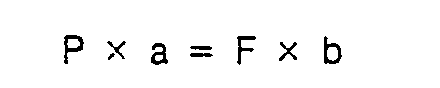
- On voit que, quelle que soit la forme de réalisation décrite, chaque attache à laquelle sont reliés deux godets successifs, est un élément rapporté ne faisant pas partie de l'élément de traction constitué par la seule bande. Cette disposition évite de transmettre à la bande les sollicitations individuelles auxquelles sont soumises les articulations des godets, certaines composantes de ces sollicitations s'annulant au niveau de la résultante.
- L'invention doit être comprise indépendamment de la position des attaches, qui peuvent être fixées, soit en position centrale sur la bande, soit en regard sur les deux bords de celle-ci.
Claims (3)
Priority Applications (1)
| Application Number | Priority Date | Filing Date | Title |
|---|---|---|---|
| AT84400222T ATE26955T1 (de) | 1983-02-11 | 1984-02-02 | Vorrichtung zum befestigen von bechern an einem foerderband insbesondere fuer becherelevatoren. |
Applications Claiming Priority (2)
| Application Number | Priority Date | Filing Date | Title |
|---|---|---|---|
| FR8302207A FR2540842A1 (fr) | 1983-02-11 | 1983-02-11 | Dispositif de fixation de godets sur la bande d'un transporteur, notamment d'un elevateur a godets |
| FR8302207 | 1983-02-11 |
Publications (2)
| Publication Number | Publication Date |
|---|---|
| EP0117791A1 EP0117791A1 (fr) | 1984-09-05 |
| EP0117791B1 true EP0117791B1 (fr) | 1987-05-06 |
Family
ID=9285830
Family Applications (1)
| Application Number | Title | Priority Date | Filing Date |
|---|---|---|---|
| EP84400222A Expired EP0117791B1 (fr) | 1983-02-11 | 1984-02-02 | Dispositif de fixation de godets sur la bande d'un transporteur, notamment d'un élévateur à godets |
Country Status (11)
| Country | Link |
|---|---|
| EP (1) | EP0117791B1 (fr) |
| JP (1) | JPS59149214A (fr) |
| AT (1) | ATE26955T1 (fr) |
| AU (1) | AU559349B2 (fr) |
| CA (1) | CA1228827A (fr) |
| DE (1) | DE3463484D1 (fr) |
| ES (1) | ES285467Y (fr) |
| FR (1) | FR2540842A1 (fr) |
| MX (1) | MX158864A (fr) |
| OA (1) | OA07657A (fr) |
| ZA (1) | ZA84393B (fr) |
Cited By (1)
| Publication number | Priority date | Publication date | Assignee | Title |
|---|---|---|---|---|
| DE19919497A1 (de) * | 1999-04-29 | 2000-11-02 | Iwk Verpackungstechnik Gmbh | Fördervorrichtung in einer Verpackungsmaschine |
Families Citing this family (5)
| Publication number | Priority date | Publication date | Assignee | Title |
|---|---|---|---|---|
| DE102015002185A1 (de) * | 2015-02-20 | 2016-08-25 | Interroll Holding Ag | Befestigungselement zum Befestigen eines Laufwagens an einem Endlosfördermittel, Laufwagen, Fördervorrichtung und Befestigungsverfahren |
| CN106315118B (zh) * | 2016-08-30 | 2018-11-20 | 上海市基础工程集团有限公司 | 单体链式土方垂直提升装置 |
| CN108394677B (zh) * | 2018-02-12 | 2020-01-24 | 陈烈康 | 渔格循环提升机 |
| CN110314601A (zh) * | 2019-07-27 | 2019-10-11 | 芜湖聚创新材料有限责任公司 | 一种自动化高效率芯材打浆系统 |
| CN116081246B (zh) * | 2023-04-06 | 2023-07-07 | 合肥曜熠建设工程有限公司 | 一种防撒漏的建筑防水材料装载用输送机 |
Family Cites Families (4)
| Publication number | Priority date | Publication date | Assignee | Title |
|---|---|---|---|---|
| FR690582A (fr) * | 1929-05-01 | 1930-09-23 | Chaine Cablee Sa | Transporteur sans fin à commande funiculaire |
| US3174616A (en) * | 1962-10-15 | 1965-03-23 | Rex Chainbelt Inc | Conveyor chain and attachment |
| FR1475928A (fr) * | 1966-02-24 | 1967-04-07 | Convoyeur à cellules pour forte pente et grands débits | |
| AT343533B (de) * | 1976-08-06 | 1978-06-12 | Doubrava Kg | Gurtbecherwerk |
-
1983
- 1983-02-11 FR FR8302207A patent/FR2540842A1/fr active Granted
-
1984
- 1984-01-03 CA CA000444587A patent/CA1228827A/fr not_active Expired
- 1984-01-13 ES ES1984285467U patent/ES285467Y/es not_active Expired
- 1984-01-18 ZA ZA84393A patent/ZA84393B/xx unknown
- 1984-01-19 MX MX200089A patent/MX158864A/es unknown
- 1984-01-20 JP JP59007381A patent/JPS59149214A/ja active Pending
- 1984-01-23 AU AU23680/84A patent/AU559349B2/en not_active Ceased
- 1984-02-02 DE DE8484400222T patent/DE3463484D1/de not_active Expired
- 1984-02-02 EP EP84400222A patent/EP0117791B1/fr not_active Expired
- 1984-02-02 AT AT84400222T patent/ATE26955T1/de not_active IP Right Cessation
- 1984-02-10 OA OA58230A patent/OA07657A/fr unknown
Cited By (1)
| Publication number | Priority date | Publication date | Assignee | Title |
|---|---|---|---|---|
| DE19919497A1 (de) * | 1999-04-29 | 2000-11-02 | Iwk Verpackungstechnik Gmbh | Fördervorrichtung in einer Verpackungsmaschine |
Also Published As
| Publication number | Publication date |
|---|---|
| AU2368084A (en) | 1984-08-16 |
| MX158864A (es) | 1989-03-22 |
| ATE26955T1 (de) | 1987-05-15 |
| DE3463484D1 (en) | 1987-06-11 |
| EP0117791A1 (fr) | 1984-09-05 |
| ES285467Y (es) | 1986-09-01 |
| OA07657A (fr) | 1985-05-23 |
| ZA84393B (en) | 1985-01-30 |
| ES285467U (es) | 1986-02-01 |
| CA1228827A (fr) | 1987-11-03 |
| FR2540842A1 (fr) | 1984-08-17 |
| AU559349B2 (en) | 1987-03-05 |
| JPS59149214A (ja) | 1984-08-27 |
| FR2540842B1 (fr) | 1985-05-10 |
Similar Documents
| Publication | Publication Date | Title |
|---|---|---|
| FR2504964A1 (fr) | Element d'echafaudage | |
| EP0468841B1 (fr) | Convoyeur à bande sans fin | |
| CA1228827A (fr) | Dispositif de fixation de godets sur la bande d'un transporteur, notamment d'un elevateur a godets | |
| EP0195721A1 (fr) | Dispositif d'antidécrochage pour porte coulissante | |
| EP0104110A2 (fr) | Dérailleur de pédalier perfectionné pour bicyclette | |
| FR2572246A1 (fr) | Dispositif de fauchage | |
| EP0338888A1 (fr) | Dispositif d'arrêt en rotation d'un élément articulé | |
| EP3727619B1 (fr) | Fixation de planche des neiges comprenant une butée de chaussage formée dans un fond-de-coque par un axe de rotation d'une coque d'appui par rapport a une embase | |
| EP0204610A1 (fr) | Dispositif de coupe pour tronçonneuse, notamment pour découper des matériaux tendres, collants ou encrassants | |
| FR2503050A1 (fr) | Dispositif de fixation d'une seconde roue pour former une roue double, en particulier sur un tracteur | |
| EP0354104A1 (fr) | Système de fixation d'une barre,, en particulier d'une barre de toit pour véhicule automobile | |
| FR2604143A1 (fr) | Arceau de commande d'une planche a voile et raccord de fixation d'un tel arceau | |
| FR2889239A1 (fr) | Porte du type a inertie compensee et dispositif anti-retombee associe | |
| FR2808701A1 (fr) | Dispositif de fixation de batons de ski et similaires | |
| EP0132721B1 (fr) | Dispositif de fixation d'une télécabine ou d'un télésiège sur un câble muni d'une surface de roulement pour galets | |
| EP1662948B1 (fr) | Dispositif de cintre a pinces asymetriques | |
| FR2679615A1 (fr) | Dispositif pour la fixation de facon amovible et reglable d'une piece sur une sangle dont les deux extremites sont fixes. | |
| EP0801617B1 (fr) | Dispositif de protection de cycles fixes sur un attelage arriere pour vehicules | |
| EP0092891A1 (fr) | Dispositif pour attacher un animal | |
| WO1996028227A1 (fr) | Fixations de raquettes a neige | |
| FR2796853A1 (fr) | Dispositif interface entre une chaussure et un ski | |
| FR2804198A1 (fr) | Dispositif de support a roulettes et a poignee telescopique et bagage souple equipe d'un tel dispositif | |
| FR2776985A1 (fr) | Porte poche poubelle telescopique transportable pour ramasseurs de papiers | |
| EP0192560B1 (fr) | Rail de guidage utilisable notamment dans un dispositif de ceinture de sécurité passive pour véhicule automobile | |
| EP0072320A3 (fr) | Lucarne à rabattement |
Legal Events
| Date | Code | Title | Description |
|---|---|---|---|
| PUAI | Public reference made under article 153(3) epc to a published international application that has entered the european phase |
Free format text: ORIGINAL CODE: 0009012 |
|
| AK | Designated contracting states |
Designated state(s): AT BE DE GB IT NL SE |
|
| 17P | Request for examination filed |
Effective date: 19850128 |
|
| ITF | It: translation for a ep patent filed | ||
| GRAA | (expected) grant |
Free format text: ORIGINAL CODE: 0009210 |
|
| AK | Designated contracting states |
Kind code of ref document: B1 Designated state(s): AT BE DE GB IT NL SE |
|
| REF | Corresponds to: |
Ref document number: 26955 Country of ref document: AT Date of ref document: 19870515 Kind code of ref document: T |
|
| REF | Corresponds to: |
Ref document number: 3463484 Country of ref document: DE Date of ref document: 19870611 |
|
| PLBE | No opposition filed within time limit |
Free format text: ORIGINAL CODE: 0009261 |
|
| STAA | Information on the status of an ep patent application or granted ep patent |
Free format text: STATUS: NO OPPOSITION FILED WITHIN TIME LIMIT |
|
| 26N | No opposition filed | ||
| PGFP | Annual fee paid to national office [announced via postgrant information from national office to epo] |
Ref country code: GB Payment date: 19900131 Year of fee payment: 7 |
|
| PGFP | Annual fee paid to national office [announced via postgrant information from national office to epo] |
Ref country code: SE Payment date: 19900206 Year of fee payment: 7 |
|
| PGFP | Annual fee paid to national office [announced via postgrant information from national office to epo] |
Ref country code: BE Payment date: 19900226 Year of fee payment: 7 |
|
| PGFP | Annual fee paid to national office [announced via postgrant information from national office to epo] |
Ref country code: AT Payment date: 19900227 Year of fee payment: 7 |
|
| ITTA | It: last paid annual fee | ||
| PGFP | Annual fee paid to national office [announced via postgrant information from national office to epo] |
Ref country code: NL Payment date: 19900228 Year of fee payment: 7 |
|
| PGFP | Annual fee paid to national office [announced via postgrant information from national office to epo] |
Ref country code: DE Payment date: 19900328 Year of fee payment: 7 |
|
| PG25 | Lapsed in a contracting state [announced via postgrant information from national office to epo] |
Ref country code: GB Effective date: 19910202 Ref country code: AT Effective date: 19910202 |
|
| PG25 | Lapsed in a contracting state [announced via postgrant information from national office to epo] |
Ref country code: SE Effective date: 19910203 |
|
| PG25 | Lapsed in a contracting state [announced via postgrant information from national office to epo] |
Ref country code: BE Effective date: 19910228 |
|
| PG25 | Lapsed in a contracting state [announced via postgrant information from national office to epo] |
Ref country code: NL Effective date: 19910901 |
|
| GBPC | Gb: european patent ceased through non-payment of renewal fee | ||
| NLV4 | Nl: lapsed or anulled due to non-payment of the annual fee | ||
| PG25 | Lapsed in a contracting state [announced via postgrant information from national office to epo] |
Ref country code: DE Effective date: 19911101 |
|
| EUG | Se: european patent has lapsed |
Ref document number: 84400222.0 Effective date: 19911008 |