EP0117774A1 - Telescopic crane jib - Google Patents
Telescopic crane jib Download PDFInfo
- Publication number
- EP0117774A1 EP0117774A1 EP84400122A EP84400122A EP0117774A1 EP 0117774 A1 EP0117774 A1 EP 0117774A1 EP 84400122 A EP84400122 A EP 84400122A EP 84400122 A EP84400122 A EP 84400122A EP 0117774 A1 EP0117774 A1 EP 0117774A1
- Authority
- EP
- European Patent Office
- Prior art keywords
- side walls
- fixed
- section
- boom according
- surface skins
- Prior art date
- Legal status (The legal status is an assumption and is not a legal conclusion. Google has not performed a legal analysis and makes no representation as to the accuracy of the status listed.)
- Withdrawn
Links
Images
Classifications
-
- B—PERFORMING OPERATIONS; TRANSPORTING
- B32—LAYERED PRODUCTS
- B32B—LAYERED PRODUCTS, i.e. PRODUCTS BUILT-UP OF STRATA OF FLAT OR NON-FLAT, e.g. CELLULAR OR HONEYCOMB, FORM
- B32B15/00—Layered products comprising a layer of metal
- B32B15/04—Layered products comprising a layer of metal comprising metal as the main or only constituent of a layer, which is next to another layer of the same or of a different material
- B32B15/046—Layered products comprising a layer of metal comprising metal as the main or only constituent of a layer, which is next to another layer of the same or of a different material of foam
-
- B—PERFORMING OPERATIONS; TRANSPORTING
- B32—LAYERED PRODUCTS
- B32B—LAYERED PRODUCTS, i.e. PRODUCTS BUILT-UP OF STRATA OF FLAT OR NON-FLAT, e.g. CELLULAR OR HONEYCOMB, FORM
- B32B15/00—Layered products comprising a layer of metal
- B32B15/04—Layered products comprising a layer of metal comprising metal as the main or only constituent of a layer, which is next to another layer of the same or of a different material
- B32B15/08—Layered products comprising a layer of metal comprising metal as the main or only constituent of a layer, which is next to another layer of the same or of a different material of synthetic resin
-
- B—PERFORMING OPERATIONS; TRANSPORTING
- B32—LAYERED PRODUCTS
- B32B—LAYERED PRODUCTS, i.e. PRODUCTS BUILT-UP OF STRATA OF FLAT OR NON-FLAT, e.g. CELLULAR OR HONEYCOMB, FORM
- B32B15/00—Layered products comprising a layer of metal
- B32B15/20—Layered products comprising a layer of metal comprising aluminium or copper
-
- B—PERFORMING OPERATIONS; TRANSPORTING
- B32—LAYERED PRODUCTS
- B32B—LAYERED PRODUCTS, i.e. PRODUCTS BUILT-UP OF STRATA OF FLAT OR NON-FLAT, e.g. CELLULAR OR HONEYCOMB, FORM
- B32B5/00—Layered products characterised by the non- homogeneity or physical structure, i.e. comprising a fibrous, filamentary, particulate or foam layer; Layered products characterised by having a layer differing constitutionally or physically in different parts
- B32B5/18—Layered products characterised by the non- homogeneity or physical structure, i.e. comprising a fibrous, filamentary, particulate or foam layer; Layered products characterised by having a layer differing constitutionally or physically in different parts characterised by features of a layer of foamed material
-
- B—PERFORMING OPERATIONS; TRANSPORTING
- B32—LAYERED PRODUCTS
- B32B—LAYERED PRODUCTS, i.e. PRODUCTS BUILT-UP OF STRATA OF FLAT OR NON-FLAT, e.g. CELLULAR OR HONEYCOMB, FORM
- B32B5/00—Layered products characterised by the non- homogeneity or physical structure, i.e. comprising a fibrous, filamentary, particulate or foam layer; Layered products characterised by having a layer differing constitutionally or physically in different parts
- B32B5/22—Layered products characterised by the non- homogeneity or physical structure, i.e. comprising a fibrous, filamentary, particulate or foam layer; Layered products characterised by having a layer differing constitutionally or physically in different parts characterised by the presence of two or more layers which are next to each other and are fibrous, filamentary, formed of particles or foamed
- B32B5/24—Layered products characterised by the non- homogeneity or physical structure, i.e. comprising a fibrous, filamentary, particulate or foam layer; Layered products characterised by having a layer differing constitutionally or physically in different parts characterised by the presence of two or more layers which are next to each other and are fibrous, filamentary, formed of particles or foamed one layer being a fibrous or filamentary layer
- B32B5/245—Layered products characterised by the non- homogeneity or physical structure, i.e. comprising a fibrous, filamentary, particulate or foam layer; Layered products characterised by having a layer differing constitutionally or physically in different parts characterised by the presence of two or more layers which are next to each other and are fibrous, filamentary, formed of particles or foamed one layer being a fibrous or filamentary layer another layer next to it being a foam layer
-
- B—PERFORMING OPERATIONS; TRANSPORTING
- B66—HOISTING; LIFTING; HAULING
- B66C—CRANES; LOAD-ENGAGING ELEMENTS OR DEVICES FOR CRANES, CAPSTANS, WINCHES, OR TACKLES
- B66C23/00—Cranes comprising essentially a beam, boom, or triangular structure acting as a cantilever and mounted for translatory of swinging movements in vertical or horizontal planes or a combination of such movements, e.g. jib-cranes, derricks, tower cranes
- B66C23/62—Constructional features or details
- B66C23/64—Jibs
- B66C23/70—Jibs constructed of sections adapted to be assembled to form jibs or various lengths
- B66C23/701—Jibs constructed of sections adapted to be assembled to form jibs or various lengths telescopic
- B66C23/707—Jibs constructed of sections adapted to be assembled to form jibs or various lengths telescopic guiding devices for telescopic jibs
-
- B—PERFORMING OPERATIONS; TRANSPORTING
- B32—LAYERED PRODUCTS
- B32B—LAYERED PRODUCTS, i.e. PRODUCTS BUILT-UP OF STRATA OF FLAT OR NON-FLAT, e.g. CELLULAR OR HONEYCOMB, FORM
- B32B2250/00—Layers arrangement
- B32B2250/40—Symmetrical or sandwich layers, e.g. ABA, ABCBA, ABCCBA
-
- B—PERFORMING OPERATIONS; TRANSPORTING
- B32—LAYERED PRODUCTS
- B32B—LAYERED PRODUCTS, i.e. PRODUCTS BUILT-UP OF STRATA OF FLAT OR NON-FLAT, e.g. CELLULAR OR HONEYCOMB, FORM
- B32B2262/00—Composition or structural features of fibres which form a fibrous or filamentary layer or are present as additives
- B32B2262/10—Inorganic fibres
- B32B2262/106—Carbon fibres, e.g. graphite fibres
-
- B—PERFORMING OPERATIONS; TRANSPORTING
- B32—LAYERED PRODUCTS
- B32B—LAYERED PRODUCTS, i.e. PRODUCTS BUILT-UP OF STRATA OF FLAT OR NON-FLAT, e.g. CELLULAR OR HONEYCOMB, FORM
- B32B2266/00—Composition of foam
- B32B2266/02—Organic
- B32B2266/0214—Materials belonging to B32B27/00
- B32B2266/0278—Polyurethane
-
- B—PERFORMING OPERATIONS; TRANSPORTING
- B32—LAYERED PRODUCTS
- B32B—LAYERED PRODUCTS, i.e. PRODUCTS BUILT-UP OF STRATA OF FLAT OR NON-FLAT, e.g. CELLULAR OR HONEYCOMB, FORM
- B32B2311/00—Metals, their alloys or their compounds
- B32B2311/24—Aluminium
Definitions
- the present invention relates to a telescopic boom of a mobile crane.
- the mobile crane telescopic jibs consist of telescopic sections which are nested one inside the other and guided relatively to each other. These sections are moved longitudinally by jacks so as to extend or retract the boom.
- the steel arrows represent a significant percentage of the total rolling weight of the crane.
- Medium cranes are single-engine cranes, the installed power of which is determined solely by road traffic, the power required for movement being significantly greater than that used for the clean work of the crane.
- the total rolling weight in which the weight of the boom intervenes affects energy consumption.
- the present invention aims to provide a telescopic boom which, for a performance equal to that of a conventional steel boom, has a lower weight.
- This lightweight design reduces the axle load and reduces the balancing counterweight. The reduction in axle loads results in longer tire life.
- the combination of reduced boom and lower center of gravity reduces braking torques on the front axle and provides better handling.
- This light design also makes it possible to attenuate the sound and vibration phenomena and provides fuel savings.
- the telescopic boom according to the invention comprises tubular sections which fit into one another so as to be guided relative to each other by means of guide members, and it is characterized in that the flanges and the side walls of the sections are formed by sandwich structures each composed of surface skins covering a central plastics core.
- the surface skins of the soles are made of a composite material formed of plastic material reinforced with fibers and the surface skins of the sandwich structures constituting the side walls are made of light alloy.
- the central core of each sandwich structure is made of plastic foam.
- the guide members are carried by the side walls.
- a mobile crane equipped with a boom comprises a carrying chassis rolling on the ground which carries an orientable turret.
- the telescopic boom generally designated by 1
- the section 2 is articulated with the turret, the other sections 3, 4 sliding in this section.
- the inclination of the boom is given by a jack articulated on the turret and on the foot section 2 of the boom.
- each tubular section 2, 3 or 4 forms in cross section a closed polygonal profile.
- the different sections have an equivalent structure, to within dimensions.
- Each section coli is formed by an upper sole (or chord) 5 and a lower sole (or chord) 6 joined by side walls 7 and 8.
- Each outer section such as 2 surrounds an adjacent inner section such as 3, providing a clearance or an annular space in which the guide members are arranged.
- each telescopic section is produced by means of a sandwich structure constituted by two surface skins 51, 61, 71, 81 covering a central core 52, 62, 72, 82 on both faces.
- the assembly of the superficial skins, of small thicknesses, on the central core, of greater thickness, is ensured by synthetic adhesives.
- the central core 52, 62, 72, 82 which separates the surface skins is constituted by a cellular plastic material or a plastic foam such as for example a polyurethane foam.
- the surface skins 51 and 61 of the soles are made of a composite material made of plastic material reinforced with high modulus carbon fibers.
- the surface skins 71 and 81 of the sidewalls are made of al - light bonding based on aluminum.
- the sandwich structures of the soles and of the side walls are rigidly fixed in them by gluing, using parts arranged in the corners and which are marked 9.
- the adjacent sections are guided vertically and laterally by guide members which are carried by the sidewalls.
- the soles because of their unidirectional structure, are unsuitable for carrying the guide members.
- Each inner section is supported on the adjacent outer section by means of longitudinal lower slides 11 which slide on lower pads 10 which are fixed to the end of this outer section, in the lower corners.
- These longitudinal slides 11 are fixed, so as to project outwardly, to the walls 7 and 8 of the inner section. They slide on the pads on sliding surfaces 12 which are parallel to the members.
- the inner section considered is also supported on the outer section by means of two upper pads 13 which slide on two longitudinal upper slides which are fixed to said outer section, in the upper corners. These upper pads 13 are fixed so as to project outwards, to the walls 7 and 8 of the section in térieur. When the inner section moves, the upper pads 13 slide on the longitudinal slides 14 along sliding surfaces 15 which are parallel to the flanges.
- the friction surfaces can be either of the plastic on plastic or plastic on metal type by bonding a metal strip in correspondence with the pads.
Abstract
Description
La présente invention se rapporte à une flèche télescopique de grue mobile.The present invention relates to a telescopic boom of a mobile crane.
Les flèches télescopiques de grue mobiles sont constituées de tronçons télescopiques qui sont emboités les uns dans les autres et guidés relativement les uns par rapport aux autres. Ces tronçons sont déplacés longitudinalement par des vérins de manière à étendre ou à rétracter la flèche.The mobile crane telescopic jibs consist of telescopic sections which are nested one inside the other and guided relatively to each other. These sections are moved longitudinally by jacks so as to extend or retract the boom.
Les grues mobiles sont équipées actuellement de flèches en acier.Mobile cranes are currently equipped with steel jibs.
Elles sont soumises à des contraintes quand à la limitation de charge par essieu et à la limitation de charge entre essieux. Les flèches en acier représentent un pourcentage non négligeable du poids total roulant de la grue.They are subject to constraints when the axle load limitation and the axle load limitation. The steel arrows represent a significant percentage of the total rolling weight of the crane.
Les grues moyennes sont des grues monomoteur dont la puissance installée est déterminée uniquement par la circulation routière, la puissance éxigée pour le déplacement étant notablement supérieure à celle utilisée pour le travail propre de la grue. Le poids total roulant dans lequel intervient le poids de la flèche joue sur la consommation d'énergie.Medium cranes are single-engine cranes, the installed power of which is determined solely by road traffic, the power required for movement being significantly greater than that used for the clean work of the crane. The total rolling weight in which the weight of the boom intervenes affects energy consumption.
Du fait de la construction en acier des flèches actuelles, et de la disposition pratique qui loge généralement la flèche au-dessus de la grue pour le transport, le centre de gravité est situé très haut ce qui pose des problèmes quand au freinage et à la tenue de route. Il se produit un transfert des charges important lors du freinage ce qui conduit à un renforcement important du freinage sur l'essieu avant. En conséquence cet essieu, particulièrement lorsqu'il est moteur, diffère notablement des essieux de poids lourds classiques.Due to the steel construction of the current jibs, and the practical arrangement which generally houses the jib above the crane for transport, the center of gravity is located very high which poses problems when braking and braking. handling. There is a significant transfer of loads during braking, which leads to significant reinforcement of the braking on the front axle. Consequently, this axle, particularly when it is powered, differs notably from conventional heavy-duty axles.
La construction en acier des flèches actuelles n'amortit pas et même amplifie les vibrations inévitables du moteur diésel et des transmissions hydrauliques.The steel construction of current arrows does not dampen and even amplifies the inevitable vibrations of the diesel engine and hydraulic transmissions.
La présente invention a pour but de fournir une flèche télescopique qui, pour une performance égale à celle d'une flèche classique en acier, présente un poids inférieur. Cette conception allégée permet de réduire la charge par essieu et de réduire le contre poids d'équilibrage. L'allégement des charges par essieu entraine une plus grande longévité des pneumatiques. La combinaison de l'allégement de la flèche et de l'abaissement du centre de gravité permet de réduire les couples de freinage sur l'essieu avant et procure une meilleure tenue de route. Cette conception allégée permet par ailleurs d'atténuer les phénomènes sonores et vibratoires et procure une économie de combustible.The present invention aims to provide a telescopic boom which, for a performance equal to that of a conventional steel boom, has a lower weight. This lightweight design reduces the axle load and reduces the balancing counterweight. The reduction in axle loads results in longer tire life. The combination of reduced boom and lower center of gravity reduces braking torques on the front axle and provides better handling. This light design also makes it possible to attenuate the sound and vibration phenomena and provides fuel savings.
La flèche télescopique selon l'invention comprend des tronçons tubulaires s'emboitant les uns dans les autres de manière à être guidés les uns par rapport aux autres par l'intermédiaire d'organes de guidage, et elle est caractérisée par le fait que les semelles et les parois latérales des tronçons sont constituées par des structures sandwichs composées chacune de peaux superficielles recouvrant une âme centrale en matière plastique.The telescopic boom according to the invention comprises tubular sections which fit into one another so as to be guided relative to each other by means of guide members, and it is characterized in that the flanges and the side walls of the sections are formed by sandwich structures each composed of surface skins covering a central plastics core.
Selon une caractéristique, les peaux superficielles des semelles sont constituées par un matériau composite formé de matière plastique renforcée de fibres et les peaux superficielles des structures sandwichs constituant les parois latérales sont en alliage léger.According to one characteristic, the surface skins of the soles are made of a composite material formed of plastic material reinforced with fibers and the surface skins of the sandwich structures constituting the side walls are made of light alloy.
Selon une autre caractéristique de l'invention, l'âme centrale de chaque structure sandwich est en mousse de plastique.According to another characteristic of the invention, the central core of each sandwich structure is made of plastic foam.
Selon une autre caractéristique de l'invention, les organes de guidage sont portés par les parois latérales.According to another characteristic of the invention, the guide members are carried by the side walls.
L'invention va maintenant être décrite avec plus de détails en se référant à un mode de réalisation donné à titre d'exemple et représenté par les dessins annexés sur lesquels :
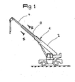
- - la figure 1 est une vue d'ensemble d'une grue mobile équipée d'une flèche télescopique.
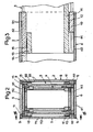
- - la figure 2 représente une coupe transversale de la flèche télescopique, selon II-II de la figure 1.
- - la figure 3 est une vue partielle selon III-III de la figure 2.
- - Figure 1 is an overview of a mobile crane equipped with a telescopic boom.
- - Figure 2 shows a cross section of the telescopic boom, according to II-II of Figure 1.
- - Figure 3 is a partial view along III-III of Figure 2.
En se référant à la figure 1, une grue mobile équipée d'une flèche selon l'invention comprend un chassis porteur roulant sur le sol lequel porte une tourelle orientable. La flèche télescopique, désignée globalement par 1, est composée de plusieurs tronçons ou caissons tubulaires 2, 3 et 4 emboités les uns dans les autres. Le tronçon 2 est articulé à la tourelle, les autres tronçons 3, 4 coulissant dans ce tronçon. L'inclinaison de la flèche est donnée par un vérin articulé sur la tourelle et sur le tronçon de pied 2 de la flèche.Referring to Figure 1, a mobile crane equipped with a boom according to the invention comprises a carrying chassis rolling on the ground which carries an orientable turret. The telescopic boom, generally designated by 1, is composed of several sections or
En se référant aux figures 2 et 3, chaque tronçon tubulaire 2, 3 ou 4 forme en coupe transversale un profil polygonal fermé. Les différents tronçons ont une structrure équivalente, aux dimensions près. Chaque tronçon est formé d'une semelle (ou membrure) supérieure 5 et d'une semelle (ou membrure) inférieure 6 réunies par des parois latérales 7 et 8. Chaque tronçon extérieur tel que 2 ceinture un tronçon intérieur adjacent tel que 3 en ménageant un jeu ou un espace annulaire dans lequel sont disposés les organes de guidage.Referring to Figures 2 and 3, each
Les semelles 5 et 6 et les parois 7 et 8 de chaque tronçon télescopique sont réalisées au moyen d'une structure sandwich constituée par deux peaux superficielles 51, 61, 71, 81 recouvrant une âme centrale 52, 62, 72, 82 sur les deux faces. L'assemblage des peaux- superficielles, de faibles épaisseurs, sur l'âme centrale, d'épaisseur plus forte, est assuré par des adhésifs de synthèse.The
L'âme centrale 52, 62, 72, 82 qui sépare les peaux superficielles est constituée par une matière plastique alvéolaire ou une mousse plastique telle que par exemple une mousse de polyuréthanne.The
Les peaux superficielles 51 et 61 des semelles sont constituées par un matériau composite constitué de matière plastique renforcée de fibres de carbone à haut module.The
Les peaux superficielles 71 et 81 des flancs sont réalisées en al- liage léger à base d'aluminium.The
Les structures sandwichs des semelles et des parois latérales sont fixées rigidement en elles par collage, à l'aide de pièces disposées dans les angles et qui sont repérées 9.The sandwich structures of the soles and of the side walls are rigidly fixed in them by gluing, using parts arranged in the corners and which are marked 9.
Les tronçons adjacents sont guidés verticalement et latéralement par des organes de guidage qui sont portés par les flancs. Les semelles en raison de leur structure unidirectionnelle, sont mal adaptées pour porter les organes de guidage.The adjacent sections are guided vertically and laterally by guide members which are carried by the sidewalls. The soles because of their unidirectional structure, are unsuitable for carrying the guide members.
Chaque tronçon intérieur s'appuie sur le tronçon extérieur adjacent au moyen de glissières inférieures longitudinales 11 qui glissent sur des patins inférieurs 10 qui sont fixés à l'extrémité de ce tronçon extérieur, dans les angles inférieurs. Ces glissières longitudinales 11 sont fixées, de manière à être saillantes vers l'extérieur, aux parois 7 et 8 du tronçon intérieur. Elles glissent sur les patins selon des surfaces de glissement 12 qui sont parallèles aux membrures.Each inner section is supported on the adjacent outer section by means of longitudinal
Le tronçon intérieur considéré s'appuie par ailleurs sur le tronçon extérieur au moyen de deux patins supérieurs 13 qui glissent sur deux glissières supérieures longitudinales qui sont fixées au dit tronçon extérieur, dans les angles supérieurs. Ces patins supérieurs 13 sont fixés de manière à être saillants vers l'extérieur, aux parois 7 et 8 du tronçon intérieur. Lors des déplacements du tronçon intérieur, les patins supérieurs 13 glissent sur les glissières longitudinales 14 selon des surfaces de glissement 15 qui sont parallèles aux semelles.The inner section considered is also supported on the outer section by means of two
Les surfaces de frottement peuvent être soit du type plastique sur plastique soit plastique sur métal par collage d'une bande métallique en correspondance avec les patins.The friction surfaces can be either of the plastic on plastic or plastic on metal type by bonding a metal strip in correspondence with the pads.
Il est bien entendu que l'on peut sans sortir du cadre de l'invention, imaginer des variantes et des perfectionnements de détails et de même envisager l'emploi de moyens équivalents.It is understood that it is possible, without departing from the scope of the invention, to imagine variants and improvements of details and even to envisage the use of equivalent means.
Claims (7)
Applications Claiming Priority (2)
| Application Number | Priority Date | Filing Date | Title |
|---|---|---|---|
| FR8300905 | 1983-01-21 | ||
| FR8300905A FR2539729A1 (en) | 1983-01-21 | 1983-01-21 | TELESCOPIC CRANE ARROW |
Publications (1)
| Publication Number | Publication Date |
|---|---|
| EP0117774A1 true EP0117774A1 (en) | 1984-09-05 |
Family
ID=9285165
Family Applications (1)
| Application Number | Title | Priority Date | Filing Date |
|---|---|---|---|
| EP84400122A Withdrawn EP0117774A1 (en) | 1983-01-21 | 1984-01-20 | Telescopic crane jib |
Country Status (2)
| Country | Link |
|---|---|
| EP (1) | EP0117774A1 (en) |
| FR (1) | FR2539729A1 (en) |
Cited By (7)
| Publication number | Priority date | Publication date | Assignee | Title |
|---|---|---|---|---|
| EP0968955A2 (en) | 1998-07-03 | 2000-01-05 | Grove U.S. LLC | Composite material jib |
| EP1090875A1 (en) * | 1999-10-06 | 2001-04-11 | Atecs Mannesmann AG | Telescopic crane boom |
| GB2387373A (en) * | 2002-04-12 | 2003-10-15 | Bamford Excavators Ltd | Composite boom for a load handling machine |
| DE202010006624U1 (en) | 2010-05-10 | 2010-08-05 | Manitowoc Crane Group France Sas | Crane jib, in particular mobile crane jib, with prestressed tension elements |
| ITMI20110862A1 (en) * | 2011-05-17 | 2012-11-18 | Cifa Spa | TELESCOPIC ARM FOR CRANES AND CRANE INCLUDING SUCH ARM |
| ITMI20110869A1 (en) * | 2011-05-17 | 2012-11-18 | Cifa Spa | TELESCOPIC ARM FOR CRANES AND CRANE INCLUDING SUCH ARM |
| CN108217478A (en) * | 2018-03-06 | 2018-06-29 | 太原科技大学 | A kind of electromagnetic type slide block device applied to telescopic arm |
Families Citing this family (1)
| Publication number | Priority date | Publication date | Assignee | Title |
|---|---|---|---|---|
| FR2759687B1 (en) * | 1997-02-14 | 1999-04-23 | Fdi Sambron | GUIDE PAD FOR TELESCOPIC BOOM AND TELESCOPIC BOOM PROVIDED WITH SUCH A GUIDE |
Citations (11)
| Publication number | Priority date | Publication date | Assignee | Title |
|---|---|---|---|---|
| US3087581A (en) * | 1960-03-07 | 1963-04-30 | Pitman Mfg Company | Fiberglas structural member and method of making same |
| CH436646A (en) * | 1966-08-10 | 1967-05-31 | Dill Ernst | Multi-part, telescopically extendable carrier |
| US3516553A (en) * | 1968-09-25 | 1970-06-23 | Tel E Lect | Boom construction |
| US3958377A (en) * | 1974-06-25 | 1976-05-25 | Milner Jr Edwin Earl | Lightweight high strength boom construction |
| US3997695A (en) * | 1975-06-12 | 1976-12-14 | Gitco, Inc. | Protective covering for fiberglass boom |
| US4003168A (en) * | 1975-06-27 | 1977-01-18 | Walter Kidde & Company, Inc. | Crane boom of trapezoidal boom sections having reinforcing rings |
| DE2634081A1 (en) * | 1976-07-29 | 1978-02-02 | Klaus Lechleitner | Crane jib of composite material - comprising box sections, opt. reinforced with glass or carbon fibre and plastics or aromatic polyamide |
| FR2401094A1 (en) * | 1977-08-26 | 1979-03-23 | Harnischfeger Corp | TELESCOPIC BOOM OF CRANE |
| GB1555271A (en) * | 1977-02-04 | 1979-11-07 | Unitex Ltd | Foam sandwich constructions |
| DE2927122A1 (en) * | 1979-07-05 | 1981-01-08 | Roehm Gmbh | METHOD FOR THE PRODUCTION OF LAYING MATERIALS FROM HARD FOAM AND FIBER REINFORCED PLASTIC |
| DE3149411A1 (en) * | 1980-12-31 | 1982-08-19 | The Warner & Swasey Co., 44106 Cleveland, Ohio | Jib of a derrick for the loading of goods |
-
1983
- 1983-01-21 FR FR8300905A patent/FR2539729A1/en not_active Withdrawn
-
1984
- 1984-01-20 EP EP84400122A patent/EP0117774A1/en not_active Withdrawn
Patent Citations (11)
| Publication number | Priority date | Publication date | Assignee | Title |
|---|---|---|---|---|
| US3087581A (en) * | 1960-03-07 | 1963-04-30 | Pitman Mfg Company | Fiberglas structural member and method of making same |
| CH436646A (en) * | 1966-08-10 | 1967-05-31 | Dill Ernst | Multi-part, telescopically extendable carrier |
| US3516553A (en) * | 1968-09-25 | 1970-06-23 | Tel E Lect | Boom construction |
| US3958377A (en) * | 1974-06-25 | 1976-05-25 | Milner Jr Edwin Earl | Lightweight high strength boom construction |
| US3997695A (en) * | 1975-06-12 | 1976-12-14 | Gitco, Inc. | Protective covering for fiberglass boom |
| US4003168A (en) * | 1975-06-27 | 1977-01-18 | Walter Kidde & Company, Inc. | Crane boom of trapezoidal boom sections having reinforcing rings |
| DE2634081A1 (en) * | 1976-07-29 | 1978-02-02 | Klaus Lechleitner | Crane jib of composite material - comprising box sections, opt. reinforced with glass or carbon fibre and plastics or aromatic polyamide |
| GB1555271A (en) * | 1977-02-04 | 1979-11-07 | Unitex Ltd | Foam sandwich constructions |
| FR2401094A1 (en) * | 1977-08-26 | 1979-03-23 | Harnischfeger Corp | TELESCOPIC BOOM OF CRANE |
| DE2927122A1 (en) * | 1979-07-05 | 1981-01-08 | Roehm Gmbh | METHOD FOR THE PRODUCTION OF LAYING MATERIALS FROM HARD FOAM AND FIBER REINFORCED PLASTIC |
| DE3149411A1 (en) * | 1980-12-31 | 1982-08-19 | The Warner & Swasey Co., 44106 Cleveland, Ohio | Jib of a derrick for the loading of goods |
Non-Patent Citations (1)
| Title |
|---|
| SCHIFF UND HAFEN, vol. 17, no. 4, avril 1965, pages 289-293, Hamburg, DE. * |
Cited By (24)
| Publication number | Priority date | Publication date | Assignee | Title |
|---|---|---|---|---|
| EP0968955A2 (en) | 1998-07-03 | 2000-01-05 | Grove U.S. LLC | Composite material jib |
| DE19829829A1 (en) * | 1998-07-03 | 2000-01-13 | Grove Us Llc Shady Grove | Composite telescopic part and boom |
| US6586084B1 (en) | 1998-07-03 | 2003-07-01 | Grove U.S. Llc | Composite material jib |
| EP1090875A1 (en) * | 1999-10-06 | 2001-04-11 | Atecs Mannesmann AG | Telescopic crane boom |
| DE19948830A1 (en) * | 1999-10-06 | 2001-04-19 | Mannesmann Ag | Telescopic boom for cranes |
| US6516962B1 (en) | 1999-10-06 | 2003-02-11 | Atecs Mannesmann Ag | Telescopic boom for cranes |
| DE19948830B4 (en) * | 1999-10-06 | 2005-11-24 | Terex-Demag Gmbh & Co. Kg | Telescopic boom for cranes |
| GB2387373A (en) * | 2002-04-12 | 2003-10-15 | Bamford Excavators Ltd | Composite boom for a load handling machine |
| GB2387375A (en) * | 2002-04-12 | 2003-10-15 | Bamford Excavators Ltd | Composite boom for a load handling machine |
| EP1361189A1 (en) * | 2002-04-12 | 2003-11-12 | J.C. Bamford Excavators Limited | Boom for a load handling machine |
| GB2387375B (en) * | 2002-04-12 | 2005-04-06 | Bamford Excavators Ltd | Boom for a load handling machine |
| US7111745B2 (en) | 2002-04-12 | 2006-09-26 | J. C. Bamford Excavators Limited | Boom for a load handling machine |
| DE202010006624U1 (en) | 2010-05-10 | 2010-08-05 | Manitowoc Crane Group France Sas | Crane jib, in particular mobile crane jib, with prestressed tension elements |
| EP2386517A1 (en) | 2010-05-10 | 2011-11-16 | Manitowoc Crane Group France SAS | Crane extension, in particular mobile crane extension, with pre-tensioned pulling elements |
| ITMI20110862A1 (en) * | 2011-05-17 | 2012-11-18 | Cifa Spa | TELESCOPIC ARM FOR CRANES AND CRANE INCLUDING SUCH ARM |
| ITMI20110869A1 (en) * | 2011-05-17 | 2012-11-18 | Cifa Spa | TELESCOPIC ARM FOR CRANES AND CRANE INCLUDING SUCH ARM |
| WO2012156807A1 (en) | 2011-05-17 | 2012-11-22 | Cifa Spa | Telescopic arm for cranes and crane comprising said arm |
| WO2013050838A1 (en) | 2011-05-17 | 2013-04-11 | Cifa Spa | Composite telescopic crane arm with metal guide blocks and crane comprising said arm |
| CN103702921A (en) * | 2011-05-17 | 2014-04-02 | 西法股份公司 | Composite telescopic crane arm with metal guide blocks and crane comprising the arm |
| CN103764542A (en) * | 2011-05-17 | 2014-04-30 | 西法股份公司 | Telescopic arm for cranes and crane comprising said arm |
| CN103702921B (en) * | 2011-05-17 | 2015-10-07 | 西法股份公司 | There is the composite telescopic crane jib of metal orienting lug and comprise the hoisting crane of described arm |
| CN103764542B (en) * | 2011-05-17 | 2016-03-23 | 西法股份公司 | For hoisting crane telescopic boom, comprise the hoisting crane of this arm and obtain the method for this arm |
| CN108217478A (en) * | 2018-03-06 | 2018-06-29 | 太原科技大学 | A kind of electromagnetic type slide block device applied to telescopic arm |
| CN108217478B (en) * | 2018-03-06 | 2024-04-12 | 太原科技大学 | Electromagnetic type sliding block device applied to telescopic arm |
Also Published As
| Publication number | Publication date |
|---|---|
| FR2539729A1 (en) | 1984-07-27 |
Similar Documents
| Publication | Publication Date | Title |
|---|---|---|
| EP0117774A1 (en) | Telescopic crane jib | |
| US20080106111A1 (en) | Ladder Assembly for a Tailgate of a Truck | |
| US7866700B2 (en) | Machine frame | |
| FR2681305A1 (en) | RETRACTABLE RUNNING TRAIN FOR A NON - CONTACT SUSTAINABLE VEHICLE. | |
| FR2977554A1 (en) | Terrestrial vehicle e.g. commercial vehicle, for transporting e.g. goods, has external resistant belt attached with external circumference of plate by complete and rigid connection and placed between structures of passages of wheels | |
| FR2810609A1 (en) | Road/rail transport wagon has road vehicle carrier connected to at least one of waggon's end platforms by lockable and detachable coupling | |
| GB2387375A (en) | Composite boom for a load handling machine | |
| EP1609669B1 (en) | Auxiliary chassis structure for haulage trucks with three axles, steerable, with tipping body. | |
| EP0027397A1 (en) | Bearing frame for a mobile engine such as a hydraulic excavator | |
| EP1184261B1 (en) | Body structure with reinforced lower beams | |
| FR2946402A1 (en) | NODE | |
| EP0325064A1 (en) | Improvement to the stability of forklift trucks with telescopic arm | |
| FR2775232A1 (en) | MOTOR VEHICLE BUMPER | |
| EP0112778A1 (en) | Loading platform for carrying a truck or a goods container with adapting means for road, rail and oversea transport | |
| WO1990015748A1 (en) | Suspension device for the forks and saddle shafts of cycles or other wheeled objects | |
| FR2615157A1 (en) | Improved tractor especially for a semi-trailer | |
| GB2337965A (en) | Lift truck | |
| FR2760704A1 (en) | Boat trailer chassis in two sections | |
| FR2517615A1 (en) | Tracked vehicle for snow - has drive with no differential but clutch and brake for each track | |
| FR2821814A1 (en) | Road transport vehicle has front and rear load supporting frames that can be moved lengthwise along platform | |
| EP4051599A1 (en) | Loading pallet | |
| FR2772057A1 (en) | BACKHOE | |
| FR2796338A1 (en) | A NEW LIGHT UTILITY VEHICLE | |
| BE543577A (en) | ||
| EP1024108B1 (en) | Device for the transposition-control of a carrying structure of a vehicule |
Legal Events
| Date | Code | Title | Description |
|---|---|---|---|
| PUAI | Public reference made under article 153(3) epc to a published international application that has entered the european phase |
Free format text: ORIGINAL CODE: 0009012 |
|
| AK | Designated contracting states |
Designated state(s): AT BE CH DE FR GB IT LI LU NL SE |
|
| STAA | Information on the status of an ep patent application or granted ep patent |
Free format text: STATUS: THE APPLICATION IS DEEMED TO BE WITHDRAWN |
|
| 18D | Application deemed to be withdrawn |
Effective date: 19850507 |
|
| RIN1 | Information on inventor provided before grant (corrected) |
Inventor name: JOUFFRAY, MAURICE |