EP0117618B1 - Seismische Rückhalteeinrichtungen - Google Patents
Seismische Rückhalteeinrichtungen Download PDFInfo
- Publication number
- EP0117618B1 EP0117618B1 EP84300408A EP84300408A EP0117618B1 EP 0117618 B1 EP0117618 B1 EP 0117618B1 EP 84300408 A EP84300408 A EP 84300408A EP 84300408 A EP84300408 A EP 84300408A EP 0117618 B1 EP0117618 B1 EP 0117618B1
- Authority
- EP
- European Patent Office
- Prior art keywords
- thimble
- restraint
- vibration absorbing
- detector
- damping
- Prior art date
- Legal status (The legal status is an assumption and is not a legal conclusion. Google has not performed a legal analysis and makes no representation as to the accuracy of the status listed.)
- Expired
Links
Images

Classifications
-
- G—PHYSICS
- G01—MEASURING; TESTING
- G01T—MEASUREMENT OF NUCLEAR OR X-RADIATION
- G01T7/00—Details of radiation-measuring instruments
Definitions
- This invention relates to mechanical vibration absorbing restraint means which are used in nuclear safety systems.
- the vibration restraint means according to this invention is usable with generally cylindrical out-of-core nuclear radiation detectors which must be mechanically supported in a vertical position about a nuclear reactor vessel.
- This invention restrains the motion of a radiation detector during a seismic event and substantially absorbs vibration forces induced thereby which would otherwise be transmitted to the internal mechanism of the detector.
- the typical out-of-core radiation detector utilized in nuclear safety systems is an ion chamber of substantial length, for example about 6 to 12 feet (1.83 to 3.66 m) long.
- the ion chamber typically utilizes concentric cylindrical electrodes which are maintained a fixed distance apart, with opposed electrical potentials for attracting respectively the oppositely charged particles which are generated in the ion chamber by neutrons from the reactor core. Such ion chambers are thus used to monitor reactor activity and to indicate the operational status of the reactor.
- the ion chamber is typically mounted in an elongated tubular thimble which is typically open ended at the top and may be closed or open ended at the bottom.
- a plurality of such thimbles are spaced around the reactor vessel in a predetermined array to permit sampling of the neutron flux level in the vicinity of the reactor vessel. Seismic activity can result in the ion chamber striking the thimble wall generating significant forces which cause electrical noise to be present in the output signal from such ion chambers. This electrical noise is thought to be a result of the vibratory motion of the electrodes relative to each other in the ion chamber.
- the tubular thimbles within which the ion chamber radiation detectors are typically mounted can have a variable inside diameter, as is typical for commercially available piping which is used in forming the reactor thimbles.
- a typical 6 inch (15.28 cm) nominal diameter schedule 80 piping typically will have an inside diameter which ranges from about 5.931 inch (15.065 cm) to 5.622 inch (14.28 cm), and 6 inch (15.24 cm) nominal diameter schedule 40 pipe has a resultant inside diameter range of from about 6.197 inch (15.74 cm) to 5.964 inch (15.149 cm).
- detector support means which provides a uniform fit and support of the detector assembly for the wide range of thimble inside diameters. It has thus been necessary to provide a rather loose fit in current detector support assemblies relative to the thimble ID. This leads to high levels of acceleration and deceleration of the detector assembly during seismic activity and results in undesirable electrical signals generated by motion of the internal detector parts.
- the presently utilized detector support assemblies are also rigid assemblies and there is thus no damping of impact shocks experienced by the assembly during seismic activity.
- the qualification of neutron detectors for use in the thimble requires that the detectors be capable of operating before, during and after a seismic event. Seismic event test sequences have been developed to conservatively simulate the seismic conditions predicted for a reactor. The capability of the neutron detector to survive the seismic test depends upon the energy absorption characteristics of the detector structure and the amount of energy transmitted to that structure. Internal damage to the detector mechanism and/or excessive and noisy signal outputs can result if either the detector or its support structure are unable to dissipate the seismic energy.
- a restraint means for supporting a generally cylindrical nuclear radiation detector within a tubular thimble
- which restraint means comprises two housing segments having a spring associated therewith for attaching one said housing segment to another said housing segment in order to form a clamp-like ring which is securably connectable about the detector, the spring being operably associated with and extending from each of said housing segments for generally radial displacement relative to said detector such that the tubular thimble is contacted thereby.
- the present invention resides in a vibration absorbing restraint means for supporting a generally cylindrical nuclear radiation detector within a tubular thimble, wherein said restraint means comprises: at least two housing segments having interconnecting means associated therewith for attaching one said housing segment to another said housing segment in order to form a clamp-like ring which is securably connectable about the generally cylindrical detector, and at least one energy absorbing means operably associated with and extending from each of said housing segments for generally radial displacement relative to said detector such that the tubular thimble is contacted thereby, characterised in that each energy absorbing means includes a thimble contacting means and a motion damping means disposed between the thimble contacting means and one of the housing segments.
- the thimble contacting means is electrically non-conductive and the damping means is characterized by resiliency and a lack of resonance.
- an elongated vertically disposed tubular thimble 11 is one of a plurality of such thimbles which are disposed about a nuclear reactor vessel within the containment building of a nuclear power plant.
- the thimble 11 is typically a 6 or 7 inch (15.24 or 17.78 cm) nominal diameter schedule 40 or schedule 80 pipe, which is open at the upper end, and may be closed or open at the bottom end.
- An elongated, generally cylindrical nuclear radiation detector 13 is mounted within the thimble 11 in a generally coaxial relationship therewith.
- the radiation detector 13 is typically of the ion chamber type which has an outside diameter of about 3 inches (7.62 cm) and ranges from approximately one foot (30.48 cm) to about 12 feet (3.66 m) long.
- Electrical leads 15 extend from one end of the radiation detector 13 and are in communication with a remotely located control system which provides operating input potential and an output signal measuring means. The radiation detector 13 generates an output signal which is indicative of nuetron flux passing through the detector.
- a plurality of vibration absorbing restraint means are longitudinally spaced along the length of the cylindrical radiation detector 13 and are securely connected thereto to provide a support means for the detector 13 within the thimble 11.
- the seismic restraint means 17a and 17b are identical in structure.
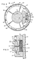
- One such restraint means 17a is best seen in detail in Figures 2 and 3.
- the restraint means 17a comprises a plurality of housing segments 19a, 19b, 19c, 19d and 19e, each having an arcuate interior surface 21 with a radius of curvature slightly larger than the generally cylindrical radiation detector 13.
- the individual housing segments 19a through 19e are brought together about the detector 13, with a plurality of fastening means generally indicated by the reference character 23, securely connecting the plurality of housing segments to the detector 13.
- the fastening means 23 each comprise a bolt 25 passing through an aperture 27 in each of a contiguous pair of housing segments.
- the bolt 25 is secured by a lock nut 29 and provided with washers 31.
- the housing segments can be secured together by a fastening means which comprises a bolt passing through an aperture in a first housing segment and engaging a threaded aperture in a second housing segment.
- a fastening means which comprises a bolt passing through an aperture in a first housing segment and engaging a threaded aperture in a second housing segment.
- each housing segment is provided with a pair of apertures, one of which is threaded to securely receive a bolt therein.
- the plurality of housing segments When the plurality of housing segments are fastened together, they define a generally circular seismic restraint means 17a about the cylindrical detector 13.
- the preferably circular perimeter 33 of the seismic restraint means 17a has a slightly smaller diameter than the inside diameter 35 of the thimble 11.
- a housing segment 19a of the restraint means 17a is best understood through consideration of Figures 2 and 3.
- the housing segment 19a includes a means generally indicated at 37 for absorbing energy generated by a seismic event.
- the energy is absorbed in a nonlinear manner as a function of displacement of the means 37, thus providing high energy dissipation within the restraint structure.
- An example of a force versus displacement function for a device according to this invention is: where F is the applied force, x is the displacement of the bearing surface with respect to its original position and a and b are constants that depend on the structure of the restraint.
- F the applied force
- x is the displacement of the bearing surface with respect to its original position
- a and b are constants that depend on the structure of the restraint.
- the force versus displacement function is nonlinear such that large displacements produce several times the restraining force that small displacements produce.
- the energy absorbing means 37 of a segment 19a is shown in cross-sectional, side elevational view in Figure 3 and includes a thimble contact means and damping means.
- a thimble contact means preferably ceramic insulator 41
- the ceramic insulator 41 provides electrical insulation between the radiation detector 13 and the thimble 11.
- the plunger member 43 is preferably circular in cross section and slidably disposed within a pad well or bore 49 in the housing segment 19a.
- the plunger member 43 is removably retained in the bore 49 by means of a C-shaped retaining ring 51 placed in a circumferentially disposed slot 53 in the inside surface 55 of the pad well 49.
- a damping means 57 consisting of a resilient material which is non-resonant.
- One such damping means is a knitted metal pad 57 disposed between the bottom of the plunger member 43 and the bottom of the pad well 49.
- the knitted metal pad 57 is preferably formed metal, mesh tubing that has been flattened and then wound to form a disk-like pad with an outside diameter slightly smallerthanthe inside diameter of the pad well 49.
- the ends 59 of the pad 57 can be welded to maintain the wound form thereof as shown.
- the pad 57 need not be and preferably is not, wound tightly, but rather the mesh tubing is wound to form a pad 57 with an annular center opening 59:
- a metal, mesh tubing which is well suited for use in the formation of a damping means is described in U.S. Patent 4,340,210, Pile Driver Cushion, by P. Townsend.
- Various other pad constructions may also be used, examples of which include stainless steel wool and a thin metal strip looped to form a sponge-like structure.
- the previously described force versus deflection function produced by the pad 57 is controlled by the characteristics of the material from which the pad is formed.
- the wire size and wire mesh size together with the forming force used in flattening and winding the tubing into a pad are controlling.
- the ceramic insulator 41 contacts the thimble structure. As the ceramic insulator and plunger compress the pad 57, a portion of the kinetic energy that would normally be imparted to the radiation detector 13 is instead absorbed by the pad 57. The pad 57 is overdamped and as a result, does not immediately spring back to the original position.
- the energy absorbing means 37 does not contribute to the detector the type of vibrational movement that is typically generated in prior seismic restraint devices. Because seismic motion is random, there is a finite probability that the energy absorbing means 37 will be subjected to a second and possibly a third blow before it recovers from the first event.
- the present energy absorbing means 37 does not experience any resonance point in the 1 hertz to 100 hertz range in which the pad 57 will effectively cease to provide restraint.
- the energy absorbing means 37 can be adapted to fit various sizes of thimbles or instrument wells through the use of one or more spacing shims 51 placed between the plunger 43 and the ceramic insulator 41.
- the seismic restraint means consisting of five segments with a single energy absorbing means in each segment has been shown, a variety of configurations are possible.
- the seismic restraint means might comprise two segments with two or three energy absorbing means therein or three segments with at least one energy absorbing means in each segment.
Landscapes
- Physics & Mathematics (AREA)
- Health & Medical Sciences (AREA)
- Life Sciences & Earth Sciences (AREA)
- General Physics & Mathematics (AREA)
- High Energy & Nuclear Physics (AREA)
- Molecular Biology (AREA)
- Spectroscopy & Molecular Physics (AREA)
- Measurement Of Radiation (AREA)
- Monitoring And Testing Of Nuclear Reactors (AREA)
- Vibration Prevention Devices (AREA)
Claims (10)
Applications Claiming Priority (2)
| Application Number | Priority Date | Filing Date | Title |
|---|---|---|---|
| US06/461,790 US4536653A (en) | 1983-01-28 | 1983-01-28 | Seismic restraint means |
| US461790 | 1983-01-28 |
Publications (2)
| Publication Number | Publication Date |
|---|---|
| EP0117618A1 EP0117618A1 (de) | 1984-09-05 |
| EP0117618B1 true EP0117618B1 (de) | 1988-07-27 |
Family
ID=23833940
Family Applications (1)
| Application Number | Title | Priority Date | Filing Date |
|---|---|---|---|
| EP84300408A Expired EP0117618B1 (de) | 1983-01-28 | 1984-01-24 | Seismische Rückhalteeinrichtungen |
Country Status (4)
| Country | Link |
|---|---|
| US (1) | US4536653A (de) |
| EP (1) | EP0117618B1 (de) |
| JP (1) | JPS59138972A (de) |
| DE (1) | DE3473051D1 (de) |
Families Citing this family (5)
| Publication number | Priority date | Publication date | Assignee | Title |
|---|---|---|---|---|
| ES2066367T3 (es) * | 1990-10-01 | 1995-03-01 | Westinghouse Electric Corp | Conjunto de detectores externos al nucleo del nivel de energia para un sistema de supervision del flujo de neutrones. |
| FR2732474B1 (fr) * | 1995-03-31 | 1997-06-13 | Sagem | Dosimetre a detecteur suspendu |
| GB9918061D0 (en) | 1999-07-30 | 1999-10-06 | Univ Bath | Modified plants |
| US7429692B2 (en) | 2004-10-14 | 2008-09-30 | Ceres, Inc. | Sucrose synthase 3 promoter from rice and uses thereof |
| US9721772B2 (en) * | 2013-01-25 | 2017-08-01 | General Electric Company | Ion chamber enclosure material to increase gamma radiation sensitivity |
Family Cites Families (10)
| Publication number | Priority date | Publication date | Assignee | Title |
|---|---|---|---|---|
| US2385857A (en) * | 1944-01-29 | 1945-10-02 | Texas Co | Cushioning device for radiation detectors |
| CA837970A (en) * | 1966-02-21 | 1970-03-31 | Shaffer Tool Works | Shock absorbing sub assembly |
| JPS5039697U (de) * | 1973-07-28 | 1975-04-23 | ||
| JPS5264593A (en) * | 1975-11-26 | 1977-05-28 | Mitsubishi Electric Corp | Neutron detector for out-core instrumentation |
| US4162619A (en) * | 1978-02-08 | 1979-07-31 | Maurer Engineering, Inc. | Drill string shock sub |
| FR2443011A1 (fr) * | 1978-11-30 | 1980-06-27 | Stein Industrie | Dispositif de supportage ou de fixation de tuyauterie |
| US4356061A (en) * | 1979-06-13 | 1982-10-26 | Scandpower, Inc. | Gamma thermometer having combined thermal bridge and centering means |
| US4340210A (en) * | 1980-01-25 | 1982-07-20 | Metex Corporation | Pile driver cushion |
| JPS5717895A (en) * | 1980-07-07 | 1982-01-29 | Mitsubishi Electric Corp | Neutron detector for nuclear reactor |
| US4504437A (en) * | 1982-05-26 | 1985-03-12 | Westinghouse Electric Corp. | Seismic restraint means for a nuclear radiation detector mounted in a tubular thimble |
-
1983
- 1983-01-28 US US06/461,790 patent/US4536653A/en not_active Expired - Lifetime
-
1984
- 1984-01-24 DE DE8484300408T patent/DE3473051D1/de not_active Expired
- 1984-01-24 EP EP84300408A patent/EP0117618B1/de not_active Expired
- 1984-01-25 JP JP59011806A patent/JPS59138972A/ja active Granted
Also Published As
| Publication number | Publication date |
|---|---|
| US4536653A (en) | 1985-08-20 |
| EP0117618A1 (de) | 1984-09-05 |
| JPH0544638B2 (de) | 1993-07-06 |
| JPS59138972A (ja) | 1984-08-09 |
| DE3473051D1 (en) | 1988-09-01 |
Similar Documents
| Publication | Publication Date | Title |
|---|---|---|
| US4689997A (en) | Motion detector suitable for detecting earthquakes and the like | |
| EP0117618B1 (de) | Seismische Rückhalteeinrichtungen | |
| US4191869A (en) | Vibration detector device | |
| US20260086255A1 (en) | Distributed optical fiber monitoring system for failure monitoring of deep rock mass | |
| US4504437A (en) | Seismic restraint means for a nuclear radiation detector mounted in a tubular thimble | |
| CA1190620A (en) | Bushing mounting device | |
| JP4918619B1 (ja) | 免振装置 | |
| GB1442494A (en) | Mechanical shock-absorbing devices | |
| US20030101794A1 (en) | Fixed beam high-g shock pulse generator apparatus and method | |
| RU2041086C1 (ru) | Датчик столкновения системы пассивной безопасности водителя легкового автомобиля | |
| US4195528A (en) | Fault detection device | |
| JP2001289988A (ja) | 原子炉圧力容器の支持装置および原子炉 | |
| Hara et al. | Basic concepts about application of dual vibration absorbers to seismic design of nuclear piping systems | |
| KR20240102556A (ko) | 내진용 케이블 트레이 행거장치 | |
| JPS58645A (ja) | 柱体用制振装置 | |
| DE2021031A1 (de) | Verfahren und Vorrichtung zur Verhuetung von Erdbebenschaeden an Gebaeuden | |
| US3359538A (en) | Pendulum type seismograph | |
| WO2022025878A1 (en) | Hybrid impact passive energy absorber | |
| KR101857440B1 (ko) | 핵융합로 플라즈마 진단장비용 진동감쇠장치 | |
| US5271283A (en) | Ballistic impulse gauge | |
| RU2768882C1 (ru) | Устройство защиты внутреннего объёма помещения атомной электростанции от осколков стены, поврежденной ударом извне | |
| Seto et al. | Basic Concept about Application of Dual Vibration Absorbers to Seismic Design of Nuclear Piping Systems | |
| JPS61180083A (ja) | 配管支持装置 | |
| JPH06235656A (ja) | 地震計 | |
| JP3174625B2 (ja) | シンブルチューブ炉内接触状況の確認方法 |
Legal Events
| Date | Code | Title | Description |
|---|---|---|---|
| PUAI | Public reference made under article 153(3) epc to a published international application that has entered the european phase |
Free format text: ORIGINAL CODE: 0009012 |
|
| AK | Designated contracting states |
Designated state(s): DE FR GB IT |
|
| 17P | Request for examination filed |
Effective date: 19850304 |
|
| 17Q | First examination report despatched |
Effective date: 19860613 |
|
| GRAA | (expected) grant |
Free format text: ORIGINAL CODE: 0009210 |
|
| AK | Designated contracting states |
Kind code of ref document: B1 Designated state(s): DE FR GB IT |
|
| REF | Corresponds to: |
Ref document number: 3473051 Country of ref document: DE Date of ref document: 19880901 |
|
| ET | Fr: translation filed | ||
| ITF | It: translation for a ep patent filed | ||
| PLBE | No opposition filed within time limit |
Free format text: ORIGINAL CODE: 0009261 |
|
| STAA | Information on the status of an ep patent application or granted ep patent |
Free format text: STATUS: NO OPPOSITION FILED WITHIN TIME LIMIT |
|
| 26N | No opposition filed | ||
| PGFP | Annual fee paid to national office [announced via postgrant information from national office to epo] |
Ref country code: FR Payment date: 19891222 Year of fee payment: 7 |
|
| ITTA | It: last paid annual fee | ||
| PGFP | Annual fee paid to national office [announced via postgrant information from national office to epo] |
Ref country code: DE Payment date: 19900330 Year of fee payment: 7 |
|
| PG25 | Lapsed in a contracting state [announced via postgrant information from national office to epo] |
Ref country code: FR Effective date: 19910930 |
|
| PG25 | Lapsed in a contracting state [announced via postgrant information from national office to epo] |
Ref country code: DE Effective date: 19911001 |
|
| REG | Reference to a national code |
Ref country code: FR Ref legal event code: ST |
|
| REG | Reference to a national code |
Ref country code: GB Ref legal event code: IF02 |
|
| PGFP | Annual fee paid to national office [announced via postgrant information from national office to epo] |
Ref country code: GB Payment date: 20021210 Year of fee payment: 20 |
|
| PG25 | Lapsed in a contracting state [announced via postgrant information from national office to epo] |
Ref country code: GB Free format text: LAPSE BECAUSE OF EXPIRATION OF PROTECTION Effective date: 20040123 |
|
| REG | Reference to a national code |
Ref country code: GB Ref legal event code: PE20 |