EP0116530A1 - Nockenventil mit einem sich selbst zentrisch einstellbaren Sitz - Google Patents
Nockenventil mit einem sich selbst zentrisch einstellbaren Sitz Download PDFInfo
- Publication number
- EP0116530A1 EP0116530A1 EP84870019A EP84870019A EP0116530A1 EP 0116530 A1 EP0116530 A1 EP 0116530A1 EP 84870019 A EP84870019 A EP 84870019A EP 84870019 A EP84870019 A EP 84870019A EP 0116530 A1 EP0116530 A1 EP 0116530A1
- Authority
- EP
- European Patent Office
- Prior art keywords
- valve
- seat ring
- sealing
- seal
- pressure
- Prior art date
- Legal status (The legal status is an assumption and is not a legal conclusion. Google has not performed a legal analysis and makes no representation as to the accuracy of the status listed.)
- Granted
Links
- 238000007789 sealing Methods 0.000 claims abstract description 40
- 239000012530 fluid Substances 0.000 claims abstract description 38
- 230000002457 bidirectional effect Effects 0.000 claims abstract description 10
- 230000009471 action Effects 0.000 claims abstract description 8
- 230000014759 maintenance of location Effects 0.000 claims description 4
- 230000004044 response Effects 0.000 claims description 3
- 230000000903 blocking effect Effects 0.000 claims description 2
- 230000002093 peripheral effect Effects 0.000 claims 1
- 238000013461 design Methods 0.000 description 8
- 239000000463 material Substances 0.000 description 6
- 238000004519 manufacturing process Methods 0.000 description 4
- 238000012856 packing Methods 0.000 description 4
- 238000010276 construction Methods 0.000 description 3
- 230000003628 erosive effect Effects 0.000 description 3
- 230000007246 mechanism Effects 0.000 description 3
- 239000002184 metal Substances 0.000 description 3
- 230000006835 compression Effects 0.000 description 2
- 238000007906 compression Methods 0.000 description 2
- 230000007797 corrosion Effects 0.000 description 2
- 238000005260 corrosion Methods 0.000 description 2
- 230000004048 modification Effects 0.000 description 2
- 238000012986 modification Methods 0.000 description 2
- 229910000619 316 stainless steel Inorganic materials 0.000 description 1
- 229910000677 High-carbon steel Inorganic materials 0.000 description 1
- 238000006243 chemical reaction Methods 0.000 description 1
- 238000006073 displacement reaction Methods 0.000 description 1
- 238000003780 insertion Methods 0.000 description 1
- 230000037431 insertion Effects 0.000 description 1
- 238000009434 installation Methods 0.000 description 1
- 238000003754 machining Methods 0.000 description 1
- 230000013011 mating Effects 0.000 description 1
- 238000000034 method Methods 0.000 description 1
Images


Classifications
-
- F—MECHANICAL ENGINEERING; LIGHTING; HEATING; WEAPONS; BLASTING
- F16—ENGINEERING ELEMENTS AND UNITS; GENERAL MEASURES FOR PRODUCING AND MAINTAINING EFFECTIVE FUNCTIONING OF MACHINES OR INSTALLATIONS; THERMAL INSULATION IN GENERAL
- F16K—VALVES; TAPS; COCKS; ACTUATING-FLOATS; DEVICES FOR VENTING OR AERATING
- F16K5/00—Plug valves; Taps or cocks comprising only cut-off apparatus having at least one of the sealing faces shaped as a more or less complete surface of a solid of revolution, the opening and closing movement being predominantly rotary
- F16K5/08—Details
- F16K5/14—Special arrangements for separating the sealing faces or for pressing them together
- F16K5/20—Special arrangements for separating the sealing faces or for pressing them together for plugs with spherical surfaces
- F16K5/204—Special arrangements for separating the sealing faces or for pressing them together for plugs with spherical surfaces with the plugs or parts of the plugs mechanically pressing the seals against the housing
-
- F—MECHANICAL ENGINEERING; LIGHTING; HEATING; WEAPONS; BLASTING
- F16—ENGINEERING ELEMENTS AND UNITS; GENERAL MEASURES FOR PRODUCING AND MAINTAINING EFFECTIVE FUNCTIONING OF MACHINES OR INSTALLATIONS; THERMAL INSULATION IN GENERAL
- F16K—VALVES; TAPS; COCKS; ACTUATING-FLOATS; DEVICES FOR VENTING OR AERATING
- F16K1/00—Lift valves or globe valves, i.e. cut-off apparatus with closure members having at least a component of their opening and closing motion perpendicular to the closing faces
- F16K1/16—Lift valves or globe valves, i.e. cut-off apparatus with closure members having at least a component of their opening and closing motion perpendicular to the closing faces with pivoted closure-members
- F16K1/18—Lift valves or globe valves, i.e. cut-off apparatus with closure members having at least a component of their opening and closing motion perpendicular to the closing faces with pivoted closure-members with pivoted discs or flaps
- F16K1/22—Lift valves or globe valves, i.e. cut-off apparatus with closure members having at least a component of their opening and closing motion perpendicular to the closing faces with pivoted closure-members with pivoted discs or flaps with axis of rotation crossing the valve member, e.g. butterfly valves
- F16K1/226—Shaping or arrangements of the sealing
- F16K1/2263—Shaping or arrangements of the sealing the sealing being arranged on the valve seat
-
- F—MECHANICAL ENGINEERING; LIGHTING; HEATING; WEAPONS; BLASTING
- F16—ENGINEERING ELEMENTS AND UNITS; GENERAL MEASURES FOR PRODUCING AND MAINTAINING EFFECTIVE FUNCTIONING OF MACHINES OR INSTALLATIONS; THERMAL INSULATION IN GENERAL
- F16K—VALVES; TAPS; COCKS; ACTUATING-FLOATS; DEVICES FOR VENTING OR AERATING
- F16K1/00—Lift valves or globe valves, i.e. cut-off apparatus with closure members having at least a component of their opening and closing motion perpendicular to the closing faces
- F16K1/16—Lift valves or globe valves, i.e. cut-off apparatus with closure members having at least a component of their opening and closing motion perpendicular to the closing faces with pivoted closure-members
- F16K1/18—Lift valves or globe valves, i.e. cut-off apparatus with closure members having at least a component of their opening and closing motion perpendicular to the closing faces with pivoted closure-members with pivoted discs or flaps
- F16K1/22—Lift valves or globe valves, i.e. cut-off apparatus with closure members having at least a component of their opening and closing motion perpendicular to the closing faces with pivoted closure-members with pivoted discs or flaps with axis of rotation crossing the valve member, e.g. butterfly valves
- F16K1/226—Shaping or arrangements of the sealing
- F16K1/228—Movable sealing bodies
- F16K1/2285—Movable sealing bodies the movement being caused by the flowing medium
-
- F—MECHANICAL ENGINEERING; LIGHTING; HEATING; WEAPONS; BLASTING
- F16—ENGINEERING ELEMENTS AND UNITS; GENERAL MEASURES FOR PRODUCING AND MAINTAINING EFFECTIVE FUNCTIONING OF MACHINES OR INSTALLATIONS; THERMAL INSULATION IN GENERAL
- F16K—VALVES; TAPS; COCKS; ACTUATING-FLOATS; DEVICES FOR VENTING OR AERATING
- F16K5/00—Plug valves; Taps or cocks comprising only cut-off apparatus having at least one of the sealing faces shaped as a more or less complete surface of a solid of revolution, the opening and closing movement being predominantly rotary
- F16K5/06—Plug valves; Taps or cocks comprising only cut-off apparatus having at least one of the sealing faces shaped as a more or less complete surface of a solid of revolution, the opening and closing movement being predominantly rotary with plugs having spherical surfaces; Packings therefor
- F16K5/0663—Packings
- F16K5/0673—Composite packings
Definitions
- the present invention relates generally to fluid flow control valves and specifically to rotary fluid control valves of the type where a valve plug and a valve seat are brought into a fluid tight sealing engagement through an eccentric swinging movement of the valve plug.
- rotary valves of the type identified above are known in the art. Such valves are also referred to as cam ball valves and eccentric ball valves and the terms are used interchangeably herein.
- One very popular valve of this type has a rigid seat with the plug semiflexibly mounted, either through a flexible actuating arm, or through a flexible connection, between the plug and a rigid actuating arm.
- An example of such a rotary fluid control valve with a rigid seat and flexible actuating arm is found in U.S. Patent No. 3,623,696.
- Most rotary valves with rigid seats have provision for adjusting the seat in the housing to obtain the desired sealing engagement between the plug and the seat.
- U.S. Patent No. 4,118,008 shows a rotary cam ball valve with a rockable seat having tapered external walls which cooperate with corresponding tapered surfaces in the valve body for permitting angular displacement of the seat in response to forces exerted by the plug.
- U.S. Patent No. 4,215,846 shows an eccentric rotary valve in which the seat has support lips which are designed to flex when loaded by the valve plug. According to the patent, the forces are such that the flexing causes the lips to converge and form a tighter seal with the valve plug.
- valves, valve seats and plug arrangements have no doubt found utility in many different applications, they all exhibit one or more shortcomings which have prevented any particular one of the valves from being entirely suitable in a variety of different operating environments.
- the desirable characteristics for a rotary fluid control valve include tight shut-off, suitability for use in high pressure flow lines, ability of the design to withstand use with corrosive and erosive fluids, operational ease to minimize actuator loading, durability, especially resistance to wear in the seat and plug seal areas, and low manufacturing and assembly cost.
- the valves of the prior art meet many of these criteria. Those employing heavy rigid seats have excellent resistance to corrosion and physical damage to the seat, but are generally difficult to adjust for tight shut-off because they do not accommodate irregularities or misalignment between the seat and valve plug.
- valve designs incorporating thin metal seals or seats accommodate irregularities and misalignment in an effort to provide tight shut-off, but are very susceptible to corrosion and erosion damage. Further, many of the prior art valve designs are not suitable for use in high pressure flow lines.
- Rotary cam ball valves inherently experience a great deal of wear on bearings, plugs and seats because of the wiping action and generally high forces experienced during opening and closing.
- high bearing loading can lead to "galling" of the valve shaft and failure of the valve.
- Prior art rotary valves experience high load forces on their shafts and bearings when the valves are closed which detracts from their ability to operate in high pressure flowpaths. To say it another way, a rotary valve having lower friction during closure, can be used in a higher pressure drop line.
- the bearing loads and plug and seat friction forces differ substantially depending on whether the high pressure is applied to the front or rear of the plug.
- a principal object of this invention is to provide an improved rotary fluid control valve.
- Another object of this invention is to provide a fluid control valve of the rotary eccentric type which is simple to manufacture and does not require alignment of the seat.
- a further object of this invention is to provide an improved rotary plug fluid control valve which is capable of use in high pressure bidirectional flowpaths.
- a still further object of this invention is to provide a rotary plug fluid control valve which solves the problems of the prior art.
- a fluid control valve comprises a body including a valve chamber defining a flowpath, a valve shaft extending into the valve chamber, a valve plug having a spherically convex sealing surface rotatably mounted in the body for limited eccentric movement about an axis in response to movement of the valve shaft, an annular seat ring adapted for sealing engagement with the sealing surface of the valve plug to block the flowpath, means mounting the seat ring in the body for limited movement transversely of the valve plug such that the valve plug tends to center the seat ring during closure of the valve and sealing means sealing the periphery of the seat ring and the body to fluid leakage.
- a feature of the invention resides in the provision of a self-centering seat.
- Another feature of the invention resides in the provision of seal means for blocking fluid leakage in bidirectional flowpaths.
- a valve 10 includes a body 11 defining generally circular fluid ports 12 and 13 for entry and exit of fluid therethrough.
- the area of the body between the ports may be considered a valve chamber in which a flowpath exists when the valve is open.
- Body 11 may include a pair of flanges 14 and 15, of conventional construction, suitable for connecting the valve into a pipeline (not shown), generally by bolting to mating flanges coupled to the open ends of the pipeline.
- machined surfaces 16 and 17 are provided for cooperation with similar surfaces on the pipeline flanges.
- a suitable gasket may be provided between the flange surfaces to assist in obtaining the leakproof connection.
- the valve may be simply held in place by so-called "through bolting".
- valve body is flangeless and long bolts and nuts connect fhe flange on each section of pipeline to "sandwich" the valve body therebetween.
- Valve 10 includes an upright cylindrical neck portion 18 and an axially aligned bottom portion 19 for facilitating mounting of a valve shaft in the body, for example, in bearing inserts positioned out of the flowpath.
- a circular seat ring 20 is fitted into a circular recess 30 in the valve body and maintained in position by a threaded retainer ring 40 or other suitable means.
- the diameter of seat ring 20 is slightly less (about3.175mm.) than the diameter of recess 30 and its thickness is less than the depth of recess 30, the actual differences in dimension being related to the size of the fluid control valve.
- the seat ring is thus held in close proximity to a seal surface 31, machined in body 11, which forms the bottom of recess 30.
- the threaded periphery 41 of the retainer ring cooperates with a similarly threaded portion in flange 15 and is centered on the centerline of port 13.
- retainer ring 40 has four slots 42 in its external surface, positioned 90 apart, which enable use of a tool for insertion and removal of the retainer ring in the body.
- An annular gasket 29 occupies a suitable recess in the surface of shoulder 32 to help make the junction of shoulder 32 and seal surface 43 fluid tight.
- Shoulder 32 thus defines the position of seal surface 43 relative to seal surface 31 and enables seat ring 20, which has a thickness less than the distance between the seal surfaces, to axially move a small distance parallel to the centerline of port 13. Since the seat ring diameter is less than that of recess 30, the seat ring is also movable transversely of the centerline of the port.
- a cam valve mechanism 50 includes a spherically convex shaped valve plug 51, supported by a pair of webs 52 affixed to a tubular mounting sleeve 53, which, in turn, is affixed to a valve shaft 54 by a pin arrangement 55 or other suitable means.
- Actuator shaft 54 is mounted for rotational movement in body 11 by means of a lower bearing 56, in bottom portion 19, and an upper bearing 57, inserted in neck portion 18.
- both bearings include an inner and an outer circumferential channel for retention of suitable "0" rings 58 (as shown) for sealing the valve shaft, the bearing inserts and the body against leakage.
- a suitable packing material 59 and a packing nut arrangement 60 are provided at the upper part of neck portion 18.
- the packing nut arrangement 60 may be conventional and adapted to compress packing material 59.
- the particular arrangement selected will be seen to be a matter of choice and is not involved with, or part of, the present invention.
- An actuator 70 is indicated at the top of valve shaft 54 and may comprise any of a number of well known actuator mechanisms for imparting a limited rotary motion to valve shaft 54 for opening and closing the valve. Actuator 70 may be remotely controlled or it may comprise a simple manual control member.
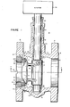
- FIGURE 2 clearly shows the offset or eccentric arrangement of the cam valve.
- the center C of valve shaft 54 is offset by a distance "d" from the centerline of spherical valve plug 51 and ports 12 and 13.
- d the centerline of spherical valve plug 51 and ports 12 and 13.
- the actuator shaft is offset from the centerline of valve plug 51, the initial contact may, for example, occur at the lower portions of valve plug 51 and seal edge 25, and valve plug 51 will urge seat ring 20 which is both laterally and axially movable with repect to the centerline of the valve plug, into its correctly centered position automatically during closure of the valve.
- seat ring 20 which is both laterally and axially movable with repect to the centerline of the valve plug, into its correctly centered position automatically during closure of the valve.
- valve of the present invention is capable of operation in higher pressure environments than prior art cam ball valves of similar size and construction because of the minimum loading on the valve seat ring, plug, bearings and shaft. Also, with the invention, lower manufacturing costs are obtainable in rotary cam valves-of comparable size and ratings.
- the valve of the present invention is also suitable for high temperature operation, involving temperatures on the order of 467° Centigrade, with proper selection of materials.
- the body may be cast of a high carbon steel such as WCB for general applications or of a type 316 stainless steel for use with corrosive and erosive fluids, if similar high quality materials are used for the seat ring and valve plug.
- the spherically convex surface of valve plug 51 is accurately machined. The flat portion on the end of the plug results from the methods used to facilitate machining and is not part of the present invention.
- the seat ring 20 in FIGURES 1 & 2 is seen to contain a pair of annular channels 21 and 22 in its opposite faces. Nested within each channel is an annular seal ring 24, having a generally "C" shaped cross section.
- the sides of the seal rings are self-biased outwardly and exert opposing forces between the bottom of the channels in the seat ring and seal surfaces 31 and 43 on body 11 and retainer ring 40, respect ively.
- the range of movement of the seat ring in the direction of flow in the preferred embodiment of a rotary valve designed for use in 15.2 m ⁇ . diameter pipelines is a minimum of 0.1524mm. and a maximum of 0.6350mm.
- the seal rings must, of course, be capable of bridging the gaps between seat ring 20 and the seal surfaces. While seat ring 20 is free to move when the valve is open, valve plug 51 forces it against retainer ring 40 when the valve is closed and the resulting gap between the seat ring and seal surface 31 must be bridged by the seal ring 24 adjacent to seal
- the valve of the invention is ideally suited for use in bidirectional flowpaths, that is, where the flow direction may be either from the right or the left.
- prior art rotary cam ball valves cannot be optimally designed for such bidirectional use since the seat-plug loading is so high. Pressure on the cam ball side of the plug determines the maximum bearing and valve shaft loads and minimum seat-plug loading. On the other hand, pressure on the back side of the plug determines the maximum seat-plug loads that are encountered.
- an optimal design for use in bidirectional flowpaths needs to compromise the tendency to leak with the excessive wear and tear on the seat-plug bearings and shaft.
- the present invention teaches a rotary cam ball design where seat-plug loading is much lower and determined primarily by the pressure in the line. Much lower wear and tear is experienced as a result and bearing and valve shaft life are enhanced.
- the leftmost seal ring 24 and channel 22 may be dispensed with.
- a "C” type seal ring pressure exerted at the open side tends to further outwardly distend the sides of the seal ring and thereby increase the sealing pressure exerted.
- "C” type seal rings permit looser tolerances than the use of 0-ring seals.
- seal ring performance is improved with increased pressure, provided the pressure is applied to the open side of the seal ring and provided, of course, that system design limits are not exceeded.
- the valve is suitable for equally effective use in flowpaths in which pressure exists on the left side of valve plug 51 as well as in flowpaths in which pressure exists on the right side of plug 51.
- valve plug 51 Assuming pressure exists on the left side of valve plug 51, fluid leakage through the junction of retainer ring 40 and seat ring 20 (seal surface 43) will be blocked by the leftmost one of seal rings 24, which opens outwardly toward the pressure side, thus tending to increase its sealing action with increased pressure. On the other hand, for pressure flow on the right side of valve plug 51, the rightmost seal ring will act in a similar manner to block fluid leakage along seal suface 31.
- the outer diameter of seat ring 20 is 3.175 mm. smaller than the diameter of recess 30 which limits the amount of transverse movement of seat ring 20.
- manufacturing tolerances of the valve parts are such that sufficient movement is permitted to enable the seat ring to be self-centering responsive to closure of the valve.
- FIGURE 3 illustrates a different .arrangement of seal rings in which the seal rings are housed in annular channels cut in the body and the retainer ring, respectively, rather than in the seat ring.
- a seat ring 120 has a substantially rectangular cross section with a rounded seal edge 23 formed on forward surface 25.
- An annular channel 33 is formed in seal surface 31 of body 11, and a similar annular channel 44 is formed in seal surface 43 of retainer ring 40.
- the seal rings are positioned within channels 33 and 44 with their open sides arranged as shown, which enables reaction to pressure on either side of seat ring 120 to increase the sealing engagement with one of the seal rings and its corresponding seal surface.
- FIGURE 4 a still different embodiment is illustrated with a single seal ring of generally "X" cross section.
- a seat ring 220 has a single channel 221 formed in one of its faces and a seal 29 having an an "X" shaped cross-section is positioned with its base bottomed in the channel and its top in contact with seal surface 31. It will be apparent that pressure on either side of the seal ring 29 tends to increase the sealing pressure against the bottom of channel 221 and the adjacent seal surface 31.
- FIGURE 5 illustrates four different types of seal rings, A, B, C and D which may advantageously be employed with the invention.
- Seal ring 24 is indicated by A and having a "C" shaped cross section, has already been described.
- Seal ring 24 is preferably fabricated of metal and exerts a substantial force upon compression.
- Seal ring 26, indicated by B has a generally "E" shaped cross section. It has a lower spring rate than seal ring 24 with a "C” shaped section. It is thus similar to seal ring 24 although slightly superior in performance and should be employed with the open end of the E facing the presssure side.
- Seal ring 27,'indicated by C is similar to seal ring 24 but includes a coiled spring for increased resistance to compression. It therefore tends to keep its shape.
- Seal ring 29 may comprise a metal body coated with plastic, or an all plastic body.
- Seal ring 29, indicated by “D” has the "X" shaped cross section just discussed in connection with FIGURE 4 and essentially functions like two back-to-back “C” seals. All of the seal rings are suitable for use in the valve of the invention. Their illustration merely indicates a range of useful equivalent parts. Conventional "0" ring seals may also be used in suitable environments where high pressures are not encountered. However, tighter tolerances between the seat and the machined surfaces and the channel depth will need to be maintained.
- FIGURE 6 is a perspective view of retainer ring 40 illustrating its general construction. Threaded surface 41 cooperates with corresponding threads in the body and slots 42 facilitate use of a tool for installation and removal of the retainer ring. It will be apparent that all of the valve parts are removable for service and replacement, if required. The slotted face of the retainer ring needs no special finishing.
- FIGURE 7 illustrates a partially broken away view of seat ring 20 showing annular channels 21 and 22 with seal rings 24 positioned therein.
- the broken away section clearly shows the arrangement of seal rings 24 within the channels.
- FIGURE 8 depicts a "soft seat” version of a seat ring useful with the invention.
- seat ring 320 includes channels 21 and 22 having seal rings 24, as previously described, positioned therein.
- a "U" shaped slot 321 is formed in the rounded surface of the seat ring that normally contacts the valve plug in a sealing engagement and a ring of suitable plastic material 322 is supported in the slot.
- the plastic material provides a soft seal surface for the valve plug.
- a resilient seal is incorporated with the self-centering seat ring and provides a useful arrangement for certain operating environments, such as those requiring extremely tight shutoff.
- FIGURE 9 illustrates still another arrangement of a soft seat in the self-centering seat ring.
- a two piece seat ring comprising a front portion 420 and a rear portion 421, is arranged to hold a previously formed plastic ring 422 between them.
- Each of portions 420 and 421 includes a respective channel 22 and 21 retaining an appropriately positioned seal ring 24.
- the two pieces may be held together by any convenient means.
- FIGURE 10 a further modification of a seat ring is illustrated wherein two seal rings are provided on the outer periphery of the seat ring rather than in its faces.
- a seat ring 520 has a pair of channels 521 formed in its periphery, within which oppositely facing seal rings 24 of "C" cross section are disposed,
- the seal rings being positioned in a back-to-back arrangement with their open sides facing outwardly, operate substantially as previously described to block fluid leakage from either direction.
- the seal rings must be capable of rather large flexures in order to effectively seal in the presence of the relatively large transverse self-centering movement of the seat ring 420 during closure of valve 51.
Landscapes
- Engineering & Computer Science (AREA)
- General Engineering & Computer Science (AREA)
- Mechanical Engineering (AREA)
- Taps Or Cocks (AREA)
- Lift Valve (AREA)
- Sliding Valves (AREA)
Applications Claiming Priority (2)
| Application Number | Priority Date | Filing Date | Title |
|---|---|---|---|
| US06/466,186 US4519579A (en) | 1983-02-14 | 1983-02-14 | Cam valve self-centering seat |
| US466186 | 1983-02-14 |
Publications (2)
| Publication Number | Publication Date |
|---|---|
| EP0116530A1 true EP0116530A1 (de) | 1984-08-22 |
| EP0116530B1 EP0116530B1 (de) | 1987-04-08 |
Family
ID=23850843
Family Applications (1)
| Application Number | Title | Priority Date | Filing Date |
|---|---|---|---|
| EP84870019A Expired EP0116530B1 (de) | 1983-02-14 | 1984-02-13 | Nockenventil mit einem sich selbst zentrisch einstellbaren Sitz |
Country Status (6)
| Country | Link |
|---|---|
| US (1) | US4519579A (de) |
| EP (1) | EP0116530B1 (de) |
| JP (1) | JPS59205072A (de) |
| CA (1) | CA1225980A (de) |
| DE (1) | DE3463077D1 (de) |
| FI (1) | FI74336C (de) |
Cited By (9)
| Publication number | Priority date | Publication date | Assignee | Title |
|---|---|---|---|---|
| EP0604835A1 (de) * | 1992-12-31 | 1994-07-06 | ARCA REGLER GmbH | Klappenventil |
| WO2009148755A1 (en) * | 2008-06-06 | 2009-12-10 | Fisher Controls International Llc | Valve trim retention apparatus |
| CN104315190A (zh) * | 2014-09-18 | 2015-01-28 | 浙江中控流体技术有限公司 | 一种偏心旋转阀阀芯锁紧装置 |
| CN111542714A (zh) * | 2018-01-10 | 2020-08-14 | 旭有机材株式会社 | 蝶形阀 |
| CN113062996A (zh) * | 2021-03-16 | 2021-07-02 | 瑞昌市金宇铜业制造有限公司 | 一种防磨损的球阀 |
| EP3865745A1 (de) * | 2020-02-14 | 2021-08-18 | MCC Holdings, Inc. d/b/a Crane ChemPharma & Energy | Ventil mit einem ungehinderten strömungsweg mit erhöhtem strömungskoeffizienten |
| EP3865742A1 (de) * | 2020-02-14 | 2021-08-18 | MCC Holdings, Inc. d/b/a Crane ChemPharma & Energy | Ventil mit einem ungehinderten strömungsweg mit erhöhtem strömungskoeffizienten |
| US11519509B2 (en) | 2020-02-14 | 2022-12-06 | Crane Chempharma & Energy Corp. | Valve with unobstructed flow path having increased flow coefficient |
| US11841089B2 (en) | 2020-02-14 | 2023-12-12 | Crane Chempharma & Energy Corp. | Valve with unobstructed flow path having increased flow coefficient |
Families Citing this family (55)
| Publication number | Priority date | Publication date | Assignee | Title |
|---|---|---|---|---|
| GB8503504D0 (en) * | 1985-02-12 | 1985-03-13 | Fort Vale Eng Ltd | Butterfly valves |
| LU87467A1 (fr) * | 1989-03-06 | 1990-10-02 | Wurth Paul Sa | Dispositif d'obturation de conduites de transport de produits en vrac |
| JPH0323262U (de) * | 1989-07-18 | 1991-03-11 | ||
| JP3848447B2 (ja) * | 1996-09-25 | 2006-11-22 | 喜 順 李 | ディスク加圧型バタフライバルブ |
| US6391171B1 (en) * | 1997-05-01 | 2002-05-21 | Applied Materials, Inc. | Flangeless feed through |
| US6378842B1 (en) * | 2000-07-20 | 2002-04-30 | Delaware Capital Formation, Inc. | V-ball control valve |
| ES2187268B1 (es) * | 2001-04-02 | 2004-11-01 | Fagor, S, Coop. | Valvula de distribucion del agua en un lavavajillas. |
| US7066447B2 (en) * | 2001-04-18 | 2006-06-27 | Fisher Controls International Llc. | Sleeve valve with adjustable flow characteristics |
| US6974121B2 (en) * | 2002-03-19 | 2005-12-13 | Fisher Controls International, Inc. | Fluid flow control valve with bi-directional shutoff |
| US7484710B2 (en) * | 2002-03-19 | 2009-02-03 | Fisher Controls International Llc | Fluid flow control valve with high temperature bi-directional shutoff |
| US20040183046A1 (en) * | 2003-03-19 | 2004-09-23 | Bickell Anthony J. | Anti-scaling control element for a rotary control valve |
| GB0504055D0 (en) * | 2005-02-26 | 2005-04-06 | Red Spider Technology Ltd | Valve |
| US20060231786A1 (en) * | 2005-04-18 | 2006-10-19 | Fisher Controls International Llc | Fluid flow control valve with composition seal |
| US8177189B2 (en) * | 2006-11-06 | 2012-05-15 | The Viking Corporation | Fire protection control valve with rotating plug |
| US8100144B2 (en) * | 2006-12-28 | 2012-01-24 | Perkins Engines Company Limited | Mounting arrangement for a rotary valve |
| US8100102B2 (en) * | 2006-12-28 | 2012-01-24 | Perkins Engines Company Limited | Cylinder head for an internal combustion engine |
| US8342204B2 (en) | 2006-12-28 | 2013-01-01 | Perkins Engines Company Limited | Rotary valve for use in an internal combustion engine |
| DE102008011416A1 (de) * | 2008-02-27 | 2009-09-10 | Continental Automotive Gmbh | Turbolader mit einer Betätigungseinrichtung zum Öffnen und Schließen eines Wastegate-Kanals |
| US8281810B2 (en) * | 2008-04-30 | 2012-10-09 | The Viking Corporation | Dry valve for sprinkler system |
| US9982789B2 (en) | 2009-12-07 | 2018-05-29 | Cameron International Corporation | Self-relieving ball valve seat |
| US8720854B2 (en) * | 2010-04-30 | 2014-05-13 | Fisher Controls International Llc | Floating ball valve seal with dynamic C-seal and static C-seal |
| US8733733B2 (en) | 2010-04-30 | 2014-05-27 | Fisher Controls International Llc | Sleeve seal assembly and rotary valve having sleeve seal assembly |
| US8496226B2 (en) * | 2010-04-30 | 2013-07-30 | Fisher Controls International Llc | Floating ball valve seal with bellows and C-seal |
| FR2962185B1 (fr) * | 2010-06-30 | 2013-08-23 | Valeo Sys Controle Moteur Sas | Vanne de circulation de fluide |
| JP5615117B2 (ja) * | 2010-09-28 | 2014-10-29 | 株式会社ケーヒン | 流路開閉弁 |
| JP5690537B2 (ja) * | 2010-09-28 | 2015-03-25 | 株式会社ケーヒン | 流路開閉弁 |
| JP5362121B2 (ja) * | 2010-10-29 | 2013-12-11 | 株式会社アルバック | 凍結真空乾燥装置及び凍結粒子製造方法 |
| US9739391B2 (en) * | 2011-01-06 | 2017-08-22 | Smith & Loveless, Inc. | Check valve for a pipe section |
| US8459022B2 (en) * | 2011-02-17 | 2013-06-11 | Honeywell International Inc. | Wastegate plug |
| US20120217426A1 (en) * | 2011-02-24 | 2012-08-30 | Andrew James Berthelsen | Valve apparatus having a double-offset shaft connection |
| KR20140041692A (ko) * | 2011-06-16 | 2014-04-04 | 헴로크세미컨덕터코포레이션 | 고체 처리 밸브 |
| GB2495504B (en) | 2011-10-11 | 2018-05-23 | Halliburton Mfg & Services Limited | Downhole valve assembly |
| GB2497913B (en) | 2011-10-11 | 2017-09-20 | Halliburton Mfg & Services Ltd | Valve actuating apparatus |
| GB2497506B (en) | 2011-10-11 | 2017-10-11 | Halliburton Mfg & Services Ltd | Downhole contingency apparatus |
| GB2495502B (en) | 2011-10-11 | 2017-09-27 | Halliburton Mfg & Services Ltd | Valve actuating apparatus |
| NO20111487A1 (no) * | 2011-11-01 | 2013-01-21 | Terje Haaland As | Tetningsanordning for ventil |
| JP2013199887A (ja) * | 2012-03-26 | 2013-10-03 | Keihin Corp | 排気ガス再循環バルブ |
| JP6203504B2 (ja) * | 2013-02-18 | 2017-09-27 | コスモ工機株式会社 | 分岐装置 |
| DE112014001077T5 (de) | 2013-03-28 | 2015-11-19 | Borgwarner Inc. | Wastegate-Kugelventil |
| US9140369B2 (en) | 2013-10-15 | 2015-09-22 | Fisher Controls International Llc | Floating ball valve seal |
| JP6271259B2 (ja) * | 2014-01-10 | 2018-01-31 | 株式会社不二工機 | 制御弁 |
| CN106460643B (zh) * | 2014-06-11 | 2018-10-09 | 株式会社Ihi | 增压器 |
| CN105587882A (zh) * | 2014-10-24 | 2016-05-18 | 江苏神通阀门股份有限公司 | 一种偏心旋转调节阀 |
| US10914387B2 (en) * | 2016-04-20 | 2021-02-09 | Fisher Controls International Llc | Rotary control valve having a clamped valve seat |
| JP6371890B2 (ja) * | 2017-08-03 | 2018-08-08 | コスモ工機株式会社 | 分岐装置 |
| CN107387802A (zh) * | 2017-08-31 | 2017-11-24 | 江苏瑞朗博机械设备有限公司 | 一种内置压缩变形阀座的偏心双球面密封阀 |
| DE102018123724A1 (de) * | 2018-09-26 | 2020-03-26 | Johnson Electric Germany GmbH & Co. KG | Dichtungssystem für ein Ventil |
| GB2581849B (en) * | 2019-03-01 | 2023-06-28 | Schenck Process Europe Gmbh | Valve with pressure seal protection |
| GB2583368B (en) * | 2019-04-25 | 2021-10-13 | Schenck Process Europe Gmbh | Dome valve adjustable top plate |
| US11112015B2 (en) | 2019-06-06 | 2021-09-07 | Robert Bosch Llc | Fluid valve assembly including seal having retention features |
| US10914390B2 (en) | 2019-06-06 | 2021-02-09 | Robert Bosch Llc | Fluid valve assembly including valve body with seal retention features |
| US11054043B2 (en) | 2019-06-06 | 2021-07-06 | Robert Bosch Llc | Fluid valve assembly including fluid driven sealing |
| US11686392B2 (en) * | 2021-04-06 | 2023-06-27 | Seaworthy Innovations, LLC | Scupper valve |
| US20230323959A1 (en) * | 2022-04-06 | 2023-10-12 | Sullivan Process Controls Llc | Eccentric process control valve |
| CN117759740B (zh) * | 2024-02-22 | 2024-05-10 | 统宇流体科技有限公司 | 偏心半球阀 |
Citations (10)
| Publication number | Priority date | Publication date | Assignee | Title |
|---|---|---|---|---|
| FR1368534A (fr) * | 1963-09-06 | 1964-07-31 | Vanne avec dispositif d'étanchéité annulaire | |
| GB1225567A (de) * | 1969-04-03 | 1971-03-17 | ||
| US3623696A (en) * | 1969-12-30 | 1971-11-30 | Masoneilan Int Inc | Eccentric, sealless, rotary valve for flow control |
| US4118008A (en) * | 1975-02-11 | 1978-10-03 | Honeywell Inc. | Rotary valve |
| DE2716744A1 (de) * | 1977-04-15 | 1978-10-19 | Kamyr Valves | Klappenventil |
| US4162782A (en) * | 1978-04-10 | 1979-07-31 | Acf Industries, Incorporated | Seal assembly for butterfly valve |
| DE2848130A1 (de) * | 1978-11-06 | 1980-05-14 | Westad Armaturfab | Vorrichtung bei einem drehklappenventil |
| US4215846A (en) * | 1977-04-01 | 1980-08-05 | Honeywell Inc. | Multiportion unitary valve seat and valve incorporating it |
| US4335748A (en) * | 1980-04-14 | 1982-06-22 | Posi-Seal International, Inc. | Bidirectional control valve |
| WO1982003898A1 (en) * | 1981-05-07 | 1982-11-11 | Richards Cecil Graham | Fire safe valve |
Family Cites Families (12)
| Publication number | Priority date | Publication date | Assignee | Title |
|---|---|---|---|---|
| GB1050982A (de) * | 1900-01-01 | |||
| CA681649A (en) * | 1964-03-10 | E. Swain Frank | Butterfly valves | |
| US1859039A (en) * | 1927-09-16 | 1932-05-17 | Bryan P Joyce | Packing |
| US2454160A (en) * | 1943-08-31 | 1948-11-16 | Pfaudler Co Inc | Corrosion resisting valve |
| US3063467A (en) * | 1960-04-08 | 1962-11-13 | Mission Mfg Co | Valve seats |
| US3192690A (en) * | 1963-01-03 | 1965-07-06 | Dudley D Taylor | Sealing ring with e-shaped radial section |
| US3250510A (en) * | 1964-02-18 | 1966-05-10 | Crane Co | Self-adjustable seats for butterfly valves or the like |
| US3870071A (en) * | 1974-01-16 | 1975-03-11 | Valve Syst Int Inc | Swing check seal assembly |
| FR2364386A1 (fr) * | 1976-09-09 | 1978-04-07 | Commissariat Energie Atomique | Joint annulaire flexible |
| US4281942A (en) * | 1978-11-13 | 1981-08-04 | General Electric Company | Lubrication system for high speed spline connection and bearing |
| US4230139A (en) * | 1978-11-13 | 1980-10-28 | Domer Scaramucci | Disc valve |
| US4290581A (en) * | 1979-09-21 | 1981-09-22 | Acf Industries, Incorporated | Seat assembly for ball valves |
-
1983
- 1983-02-14 US US06/466,186 patent/US4519579A/en not_active Expired - Lifetime
-
1984
- 1984-02-13 DE DE8484870019T patent/DE3463077D1/de not_active Expired
- 1984-02-13 EP EP84870019A patent/EP0116530B1/de not_active Expired
- 1984-02-13 FI FI840558A patent/FI74336C/fi not_active IP Right Cessation
- 1984-02-13 JP JP59024941A patent/JPS59205072A/ja active Granted
- 1984-02-13 CA CA000447250A patent/CA1225980A/en not_active Expired
Patent Citations (10)
| Publication number | Priority date | Publication date | Assignee | Title |
|---|---|---|---|---|
| FR1368534A (fr) * | 1963-09-06 | 1964-07-31 | Vanne avec dispositif d'étanchéité annulaire | |
| GB1225567A (de) * | 1969-04-03 | 1971-03-17 | ||
| US3623696A (en) * | 1969-12-30 | 1971-11-30 | Masoneilan Int Inc | Eccentric, sealless, rotary valve for flow control |
| US4118008A (en) * | 1975-02-11 | 1978-10-03 | Honeywell Inc. | Rotary valve |
| US4215846A (en) * | 1977-04-01 | 1980-08-05 | Honeywell Inc. | Multiportion unitary valve seat and valve incorporating it |
| DE2716744A1 (de) * | 1977-04-15 | 1978-10-19 | Kamyr Valves | Klappenventil |
| US4162782A (en) * | 1978-04-10 | 1979-07-31 | Acf Industries, Incorporated | Seal assembly for butterfly valve |
| DE2848130A1 (de) * | 1978-11-06 | 1980-05-14 | Westad Armaturfab | Vorrichtung bei einem drehklappenventil |
| US4335748A (en) * | 1980-04-14 | 1982-06-22 | Posi-Seal International, Inc. | Bidirectional control valve |
| WO1982003898A1 (en) * | 1981-05-07 | 1982-11-11 | Richards Cecil Graham | Fire safe valve |
Cited By (18)
| Publication number | Priority date | Publication date | Assignee | Title |
|---|---|---|---|---|
| EP0604835A1 (de) * | 1992-12-31 | 1994-07-06 | ARCA REGLER GmbH | Klappenventil |
| WO2009148755A1 (en) * | 2008-06-06 | 2009-12-10 | Fisher Controls International Llc | Valve trim retention apparatus |
| US8186646B2 (en) | 2008-06-06 | 2012-05-29 | Fisher Controls International, Llc | Valve trim retention apparatus |
| CN102084162B (zh) * | 2008-06-06 | 2012-12-26 | 费希尔控制国际公司 | 阀内件保持装置 |
| RU2484346C2 (ru) * | 2008-06-06 | 2013-06-10 | Фишер Контролз Интернешнел Ллс | Устройство для фиксации регулирующих элементов клапана |
| CN104315190A (zh) * | 2014-09-18 | 2015-01-28 | 浙江中控流体技术有限公司 | 一种偏心旋转阀阀芯锁紧装置 |
| EP3739246A4 (de) * | 2018-01-10 | 2021-09-15 | Asahi Yukizai Corporation | Drosselventil |
| CN111542714A (zh) * | 2018-01-10 | 2020-08-14 | 旭有机材株式会社 | 蝶形阀 |
| TWI794388B (zh) * | 2018-01-10 | 2023-03-01 | 日商旭有機材股份有限公司 | 蝶形閥 |
| US11248713B2 (en) | 2018-01-10 | 2022-02-15 | Asahi Yukizai Corporation | Butterfly valve |
| EP3865745A1 (de) * | 2020-02-14 | 2021-08-18 | MCC Holdings, Inc. d/b/a Crane ChemPharma & Energy | Ventil mit einem ungehinderten strömungsweg mit erhöhtem strömungskoeffizienten |
| EP3865742A1 (de) * | 2020-02-14 | 2021-08-18 | MCC Holdings, Inc. d/b/a Crane ChemPharma & Energy | Ventil mit einem ungehinderten strömungsweg mit erhöhtem strömungskoeffizienten |
| US11519509B2 (en) | 2020-02-14 | 2022-12-06 | Crane Chempharma & Energy Corp. | Valve with unobstructed flow path having increased flow coefficient |
| US11841089B2 (en) | 2020-02-14 | 2023-12-12 | Crane Chempharma & Energy Corp. | Valve with unobstructed flow path having increased flow coefficient |
| US11946557B2 (en) | 2020-02-14 | 2024-04-02 | Crane Chempharma & Energy Corp. | Valve with unobstructed flow path having increased flow coefficient |
| US11953113B2 (en) | 2020-02-14 | 2024-04-09 | Crane Chempharma & Energy Corp. | Valve with unobstructed flow path having increased flow coefficient |
| CN113062996B (zh) * | 2021-03-16 | 2022-09-13 | 瑞昌市金宇铜业制造有限公司 | 一种防磨损的球阀 |
| CN113062996A (zh) * | 2021-03-16 | 2021-07-02 | 瑞昌市金宇铜业制造有限公司 | 一种防磨损的球阀 |
Also Published As
| Publication number | Publication date |
|---|---|
| DE3463077D1 (en) | 1987-05-14 |
| CA1225980A (en) | 1987-08-25 |
| EP0116530B1 (de) | 1987-04-08 |
| FI840558A0 (fi) | 1984-02-13 |
| US4519579A (en) | 1985-05-28 |
| JPH0326296B2 (de) | 1991-04-10 |
| FI840558A (fi) | 1984-08-15 |
| FI74336C (fi) | 1988-01-11 |
| FI74336B (fi) | 1987-09-30 |
| JPS59205072A (ja) | 1984-11-20 |
Similar Documents
| Publication | Publication Date | Title |
|---|---|---|
| EP0116530B1 (de) | Nockenventil mit einem sich selbst zentrisch einstellbaren Sitz | |
| US3883112A (en) | Plug valve having composite seat element | |
| US4289296A (en) | Bidirectional axially pliant pressure assisted seat for a valve | |
| US4660591A (en) | Ball valve and seat assembly | |
| US4513946A (en) | Valve and valve sealing member | |
| US4165859A (en) | Seal assembly | |
| US4750708A (en) | High strength ball valve seat assembly | |
| US4277047A (en) | Metallic sealing device for valve | |
| EP0454768B1 (de) | Kugelventil | |
| EP0110012B1 (de) | Ventileinheit | |
| US4928921A (en) | Ball valves for pipelines | |
| EP0025402B1 (de) | Ventil für Tieftemperaturbetrieb und Dichtung dafür | |
| JPH0213192B2 (de) | ||
| US4113229A (en) | Spherical valve assembly | |
| EP0216200B1 (de) | Absperrventil, insbesondere für heisse Flüssigkeiten | |
| EP0146568B1 (de) | Ventildichtung für kryogene verwendung | |
| US3397861A (en) | Valve seat with backing | |
| US4815700A (en) | Ball valve with improved seals | |
| EP0300613B1 (de) | Ventilsitz | |
| JPS6228349B2 (de) | ||
| US4335748A (en) | Bidirectional control valve | |
| US5478047A (en) | Flexible seating structure for valves | |
| EP0401443A1 (de) | Kugelventil mit kleinem Drehmoment | |
| CA1208191A (en) | Bidirectional valve seal | |
| EP0134503B1 (de) | Dichtungseinrichtung für ein Absperrorgan |
Legal Events
| Date | Code | Title | Description |
|---|---|---|---|
| PUAI | Public reference made under article 153(3) epc to a published international application that has entered the european phase |
Free format text: ORIGINAL CODE: 0009012 |
|
| AK | Designated contracting states |
Designated state(s): DE FR GB IT |
|
| 17P | Request for examination filed |
Effective date: 19850124 |
|
| 17Q | First examination report despatched |
Effective date: 19860130 |
|
| GRAA | (expected) grant |
Free format text: ORIGINAL CODE: 0009210 |
|
| AK | Designated contracting states |
Kind code of ref document: B1 Designated state(s): DE FR GB IT |
|
| REF | Corresponds to: |
Ref document number: 3463077 Country of ref document: DE Date of ref document: 19870514 |
|
| ET | Fr: translation filed | ||
| ITF | It: translation for a ep patent filed | ||
| PLBE | No opposition filed within time limit |
Free format text: ORIGINAL CODE: 0009261 |
|
| STAA | Information on the status of an ep patent application or granted ep patent |
Free format text: STATUS: NO OPPOSITION FILED WITHIN TIME LIMIT |
|
| 26N | No opposition filed | ||
| ITTA | It: last paid annual fee | ||
| PGFP | Annual fee paid to national office [announced via postgrant information from national office to epo] |
Ref country code: GB Payment date: 20000209 Year of fee payment: 17 |
|
| PGFP | Annual fee paid to national office [announced via postgrant information from national office to epo] |
Ref country code: DE Payment date: 20010205 Year of fee payment: 18 |
|
| PG25 | Lapsed in a contracting state [announced via postgrant information from national office to epo] |
Ref country code: GB Free format text: LAPSE BECAUSE OF NON-PAYMENT OF DUE FEES Effective date: 20010213 |
|
| GBPC | Gb: european patent ceased through non-payment of renewal fee |
Effective date: 20010213 |
|
| PGFP | Annual fee paid to national office [announced via postgrant information from national office to epo] |
Ref country code: FR Payment date: 20020212 Year of fee payment: 19 |
|
| PG25 | Lapsed in a contracting state [announced via postgrant information from national office to epo] |
Ref country code: DE Free format text: LAPSE BECAUSE OF NON-PAYMENT OF DUE FEES Effective date: 20020903 |
|
| PG25 | Lapsed in a contracting state [announced via postgrant information from national office to epo] |
Ref country code: FR Free format text: LAPSE BECAUSE OF NON-PAYMENT OF DUE FEES Effective date: 20031031 |
|
| REG | Reference to a national code |
Ref country code: FR Ref legal event code: ST |