EP0116353A2 - Verfahren zur Steuerung des Luft-Kraftstoff-Verhältnisses und Luft-Kraftstoff-Verhältnis-Detektor - Google Patents
Verfahren zur Steuerung des Luft-Kraftstoff-Verhältnisses und Luft-Kraftstoff-Verhältnis-Detektor Download PDFInfo
- Publication number
- EP0116353A2 EP0116353A2 EP84101116A EP84101116A EP0116353A2 EP 0116353 A2 EP0116353 A2 EP 0116353A2 EP 84101116 A EP84101116 A EP 84101116A EP 84101116 A EP84101116 A EP 84101116A EP 0116353 A2 EP0116353 A2 EP 0116353A2
- Authority
- EP
- European Patent Office
- Prior art keywords
- air
- fuel ratio
- sensor
- basis
- electromotive force
- Prior art date
- Legal status (The legal status is an assumption and is not a legal conclusion. Google has not performed a legal analysis and makes no representation as to the accuracy of the status listed.)
- Granted
Links
Images


Classifications
-
- G—PHYSICS
- G01—MEASURING; TESTING
- G01N—INVESTIGATING OR ANALYSING MATERIALS BY DETERMINING THEIR CHEMICAL OR PHYSICAL PROPERTIES
- G01N25/00—Investigating or analyzing materials by the use of thermal means
-
- G—PHYSICS
- G01—MEASURING; TESTING
- G01N—INVESTIGATING OR ANALYSING MATERIALS BY DETERMINING THEIR CHEMICAL OR PHYSICAL PROPERTIES
- G01N27/00—Investigating or analysing materials by the use of electric, electrochemical, or magnetic means
- G01N27/26—Investigating or analysing materials by the use of electric, electrochemical, or magnetic means by investigating electrochemical variables; by using electrolysis or electrophoresis
- G01N27/403—Cells and electrode assemblies
- G01N27/406—Cells and probes with solid electrolytes
- G01N27/4065—Circuit arrangements specially adapted therefor
-
- F—MECHANICAL ENGINEERING; LIGHTING; HEATING; WEAPONS; BLASTING
- F02—COMBUSTION ENGINES; HOT-GAS OR COMBUSTION-PRODUCT ENGINE PLANTS
- F02D—CONTROLLING COMBUSTION ENGINES
- F02D41/00—Electrical control of supply of combustible mixture or its constituents
- F02D41/02—Circuit arrangements for generating control signals
- F02D41/14—Introducing closed-loop corrections
- F02D41/1438—Introducing closed-loop corrections using means for determining characteristics of the combustion gases; Sensors therefor
- F02D41/1473—Introducing closed-loop corrections using means for determining characteristics of the combustion gases; Sensors therefor characterised by the regulation method
- F02D41/1474—Introducing closed-loop corrections using means for determining characteristics of the combustion gases; Sensors therefor characterised by the regulation method by detecting the commutation time of the sensor
-
- F—MECHANICAL ENGINEERING; LIGHTING; HEATING; WEAPONS; BLASTING
- F02—COMBUSTION ENGINES; HOT-GAS OR COMBUSTION-PRODUCT ENGINE PLANTS
- F02D—CONTROLLING COMBUSTION ENGINES
- F02D41/00—Electrical control of supply of combustible mixture or its constituents
- F02D41/02—Circuit arrangements for generating control signals
- F02D41/14—Introducing closed-loop corrections
- F02D41/1438—Introducing closed-loop corrections using means for determining characteristics of the combustion gases; Sensors therefor
- F02D41/1473—Introducing closed-loop corrections using means for determining characteristics of the combustion gases; Sensors therefor characterised by the regulation method
- F02D41/1475—Regulating the air fuel ratio at a value other than stoichiometry
- F02D41/1476—Biasing of the sensor
-
- F—MECHANICAL ENGINEERING; LIGHTING; HEATING; WEAPONS; BLASTING
- F02—COMBUSTION ENGINES; HOT-GAS OR COMBUSTION-PRODUCT ENGINE PLANTS
- F02D—CONTROLLING COMBUSTION ENGINES
- F02D41/00—Electrical control of supply of combustible mixture or its constituents
- F02D41/24—Electrical control of supply of combustible mixture or its constituents characterised by the use of digital means
- F02D41/2406—Electrical control of supply of combustible mixture or its constituents characterised by the use of digital means using essentially read only memories
- F02D41/2425—Particular ways of programming the data
- F02D41/2429—Methods of calibrating or learning
- F02D41/2451—Methods of calibrating or learning characterised by what is learned or calibrated
- F02D41/2474—Characteristics of sensors
-
- F—MECHANICAL ENGINEERING; LIGHTING; HEATING; WEAPONS; BLASTING
- F02—COMBUSTION ENGINES; HOT-GAS OR COMBUSTION-PRODUCT ENGINE PLANTS
- F02D—CONTROLLING COMBUSTION ENGINES
- F02D41/00—Electrical control of supply of combustible mixture or its constituents
- F02D41/24—Electrical control of supply of combustible mixture or its constituents characterised by the use of digital means
- F02D41/2406—Electrical control of supply of combustible mixture or its constituents characterised by the use of digital means using essentially read only memories
- F02D41/2425—Particular ways of programming the data
- F02D41/2429—Methods of calibrating or learning
- F02D41/2451—Methods of calibrating or learning characterised by what is learned or calibrated
- F02D41/2454—Learning of the air-fuel ratio control
Definitions
- This invention relates to a method for controlling an air/fuel ratio and to an air/fuel ratio detector suitable for use in air/fuel ratio control.
- Prior art air/fuel ratio detectors include those which detect the ratio on the leaner side from the stoichiometric air/fuel ratio and those which detect the ratio on the richer side, as disclosed in U.S. Patent Nos. 4,304,652 and 4,300,990, for example. When these detectors are used for the air/fuel ratio control of an internal combustion engine, for example, the detectors must have quick response in order to effect feedback control.
- the inventors of this invention produced a wide variety of air/fuel ratio sensors and examined their response characteristics. As a result of studies, the inventors found that if the response speed of the sensors is increased, the sensor output fails to represent a true value and accurate air/ fuel ratio control becomes impossible any longer.
- the present invention is directed to a method for controlling an air/fuel ratio and an air/fuel ratio detector which has quick response and can be used for accurate air/fuel ratio control.
- the inventors examined the sensors having quick respanse and found that the deviation of the sensor output from the true value became great particularly when the change of the air/fuel ratio with respect to time was great.
- the present invention contemplates therefore to compensate for the sensor output on the basis of the change signal component in the sensor output resulting from the change of the air/fuel ratio with respect to time.
- Figure 1 illustrates the basic construction of an example of the air/fuel ratio sensor and its characteristics.
- Figure l(a) illustrates the principle of the sensor, and electrodes 21a, 21b are shown disposed on both side of a solid electrolyte 3.
- a porous diffusion resistor 22 is disposed on the surface of the electrode 21a.
- the power source 23 is a constant current source. If a current I is caused to flow and the electromotive force (EMF) at that time is measured, the relation between the air/fuel ratio and EMG changes step-wise as shown in Figure l(b). The points where the air/fuel ratio changes varies depending upon the current applied, and the greater the current value, the closer to the lean side becomes the change point of the air/fuel ratio. Air/fuel ratio control of an engine is effected by utilizing the points which thus change step-wise. When the current value is zero, it changes at the stoichiometric air/fuel ratio point.
- EMF electromotive force
- Figure l(c) shows the characteristics of the sensor when the power source 23 is used as a constant voltage source.
- a limit current I o proportional to the oxygen concentration can be obtained.
- an analog output proportional to the oxygen concentration can be obtained if the voltage applied to the sensor is kept at V at which the limit current I o is obtained.
- Figure l(c) shows such characteristics and a current value proportional to the air/fuel ratio can be obtained. Air/fuel ratio control of the engine is effected by detecting this current value, too.
- Figure 2 shows sensors A and B to explain the problem with the air/fuel ratio sensors.
- the sensor A shown in Figure 2(a) has a thin diffusion resistor 22a and quick response but the sensor output fluctuates in accordance with the disturbance of the air/fuel ratios.
- the sensor B shown in Figure 2(b) has a thick diffusion resistor 22b, which is greater than that of the sensor A, and slow response. Hence, it can not follow up the disturbance of the air/ .. fuel ratios and the fluctuation of the sensor output is small.
- the output of the sensor A also fluctuates so that the limit current value described above deviates from the line of Figure l(c) proportional to the oxygen concentration, and hence, a true value is no longer represented.
- the sensor B having slow response does not cause such a problem. This will be illustrated by experimental data.
- Figure 3 is a diagram of the characteristics of Figure l(d) and shows the result of measurement of the current flowing through the sensors A and B that are fitted to an exhaust pipe, respectively, when the voltage applied to the sensors is changed.
- the mean air/fuel ratio (A/F) was kept constant by keeping canstant the intake air quantity and fuel supply quantity to the engine.
- the engine was operated inside a range where A/F changed remarkably.
- the signal of the sensor A having quick response fluctuated greatly but the signal of the sensor B having slow response exhibited small fluctuation as represented by a curve B.
- the difference between the limit current values Ia and Ib resulted from the deviation of the signal of the sensor A from the true value and from the difference between the diffusion resistors 22a and 22b.
- the reason why the signal of the sensor A deviates from the true value may be as follows.
- the oxygen concentration inside the exhaust pipe changes in synchronism with the revolution of the engine.
- the limit current drops in accordance with this change; but since the response of the sensor A is too good, the oxygen in the proximity of the electrode, which is covered with the thin diffusion resistor 22a, becomes temporarily short, so that the state changes from the ion conduction to the electron conduction. Hence, the current to be measured becomes greater.
- Figure 4 illustrates comparatively the limit current values Ia and Ib of the sensors A and B when the number of revolution of the engine is increased to enlarge the disturbance of the air/fuel ratio A/F while the mean air/fuel ratio is kept constant.
- Ia of the sensor A increases with the increase of ⁇ A/F but Ib of the sensor B hardly changes.
- Ia is not proportional to the air/fuel ratio when the sensor output fluctuates greatly in response to ⁇ A/F as in the case of the sensor A.
- Figure 5 illustrates the result of measurement of the change of the limit current of the sensors A and B with respect to the excess air ratio.
- This drawing corresponds to Figure l(c).
- Line A-1 represents the characteristics measured in a range where no disturbance of the air/fuel ratio ⁇ A/F exists, by the sensor A.
- Line A-2 represents the result.of measurement in a range where AA/F is great.
- lines B-1 and B-2 represent the output of the sensor B in a range where ⁇ A/F is small and in a range where ⁇ A/F is great, respectively.
- Figure 6(a) shows the result of measurement of the limit current in a range where ⁇ A/F is great and in a range where it is small, while mean A/F is kept constant.
- the limit current i's Io but where ⁇ A/F is great, the limit current becomes great such as I 1 .
- Figures 6(a) and 6(b) illustrate the results of measurement in an open loop and a closed loop, respectively.
- Figure 6(b) shows the result of the controlled A/F when the limit current I o to be applied to the sensor A is kept constant and closed loop control is effected so as to keep the air/fuel ratio constant by change of the electromotive force.
- A/F is controlled to ⁇ o but where ⁇ A/F is great, A/F is controlled to ⁇ 1 on the richer side.
- Figure 7 illustrates the change of the electromotive force of the sensor A under the conditions of Figure 6.
- the limit current value and the controlled air/fuel ratio when ⁇ A/F of the sensor B is changed exhibit substantially the constant values irrespective of ⁇ A/F.
- the sensor since its response is slow, the sensor is not suitable for control use but can be suitably used for the calibration of the air/fuel ratio.
- the output of the sensor A having quick response does not represent the true value whether the control is made by the current or by the voltage.
- the gist of the present invention resides in that compensation processing is made for the sensor output on the basis of the change signal components in the sensor output resulting from the change of the air/fuel ratio with respect to time, as described earlier.
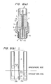
- FIG 8(a) shows the construction of the air/fuel ratio sensor 1 of this embodiment.
- a sensor portion 2 consists of a solid electrolyte 3 and electrodes printed on both sides of the electrolyte.
- the sensor portion 2 is fixed to a holder 13 by a non-conductive washer 4, a rod-like fixing member 5 and a stopper 6 having a hole.
- An atmospheric chamber 7 communicates with the atmosphere through the hole of the stopper 6.
- a heater 9 is embedded into a cover 8 and an exhaust hole 10 for the passage of an exhaust gas is bored on the cover 8.
- An adaptor 11 is integrated with the holder 13 by a caulking portion 12.
- the adaptor 11 is fitted to an exhaust pipe 15 at its screw portion 14.' In other words, the exhaust gas enters the exhaust chamber 15 through the exhaust hole 10 and the atmosphere is introduced into the atmospheric chamber 7 through the hole of the stopper 6.
- Figure 8(b) illustrates in detail the sensor portion 2.
- the portion above dot-and-dash line is on the side of the atmospheric chamber 7 while the portion below the line is on the side of the exhaust chamber 15.
- the electrode 20a is the cathode and the electrode 20b is the anode.
- the point of the stoichiometric air/fuel ratio is the point at which the electromotive force rises when the potential of the anode 20b is being measured.
- Cathode 21a and anode 21b are printed below the electrodes 20a, 20b, respectively, to detect a lean air/fuel ratio.
- the cathode 21a is covered with a diffusion resistor 22.
- a potential is applied to the anode 21b, the oxygen ion moves from the cathode 21a to the anode 21b.
- the limit current due to ion conduction flows by the movement of the oxygen ion in cooperation with the action of the diffusion resistor 22.
- Figure 9 shows the waveform of the limit current value when measured using the air/fuel sensor described above.
- the waveform in Figure 9(a) represents the case where the fluctuation of the air/fuel ratio ⁇ A/F is great and the low and high frequency components overlap with each other.
- the change of this high frequency component ⁇ I corresponds substantially to ⁇ A/F.
- ⁇ I becomes also great.
- the degree of fluctuation of ⁇ A/F can be determined by measuring this ⁇ I and the true value can be obtained.
- K represents a compensation coefficient.
- a predetermined voltage V o is applied between the electrodes 21a and 21b inside the sensor portion 20 from the power source 23.
- a limit current 1 0 proportional to the air/fuel ratio flows through the resistor R 20 . This current is detected as a terminal voltage V acrass the resistor R 20 .
- the voltage V is applied to a low frequency detection circuit 30 and to a high frequency detection circuit 31.
- the low frequency detection circuit 30 is a lowpass filter which generates a low frequency voltage VIo of the voltage V.
- the high frequency detection circuit 31 is a highpass filter which generates a high frequency voltage ⁇ V 1 of the voltage V. This voltage ⁇ V 1 is held.
- the voltage V Io is inverted and amplified and the sum of this voltage and the voltage ⁇ V I that has been held is further amplified. Accordingly, the output becomes V Io - K- ⁇ V I .
- the compensation coefficient K can be selected suitably by selecting suitable values for the two input resistors R 1 and R2 inside the circuit 3 2 .
- Figure 11 illustrates another embodiment of the present invention which represents a compensation method when the air/fuel ratio is controlled by the change of the electromotive force by constant current excitation as shown in Figure l(b).
- Figure 11(a) shows in detail the measured waveforms of the change of the electromotive force.
- Symbol V s represents the slice level.
- the waveform of the frequency component having high amplitude and proportional to ⁇ A/F remains on the waveform of the low frequency component.
- the degree of ⁇ A/F is determined by detecting this ⁇ V by the highpass filter or the like.
- the air/fuel ratio to be controlled becomes great if A/F, that is, V, is great.
- the air/fuel ratio is kept in the predetermined lean state by changing the constant of the proportional integration control when the fuel quantity is subjected to the closed loop control. If the positive integration constant a and the negative integration constant p are changed so as to increase the constant ⁇ as shown in Figure 11(b), the air/fuel ratio shifts to the lean side. Thus, the air/fuel ratio to be controlled is controlled to a desired value.
- This control can be made digitally by utilizing a microcomputer. The control will be explained with reference to Figure 12.
- Figure 12(a) is a block diagram of the internal combustion engine as a whole to be controlled
- Figure 12(b) is a detailed view of the sensor portion 20'
- Figure 12(c) is a flow chart.
- the fuel is supplied from fuel supply means 82 such as an injector or an electronic control carburetor to the air which is sucked from an air cleaner 80.
- the air/fuel mixture is burnt in the internal combustion engine 84 and is discharged from an exhaust pipe 86.
- the sensor portion 20 1 is fitted to the exhaust pipe 86.
- the construction of this sensor portion 20' is substantially the same as that of the sensor 20 shown in Figure 10 but the difference resides in that a current source is used as the power source 23' and the electromotive force V generated between the electrodes 21a and 21b is measured.
- the electromotive force generated by the sensor 20' is taken into a control unit 90 through an I/O circuit 88.
- This control unit 90 consists of heretoforeknown CPU (central processing unit), ROM (read only memory) and RAM (random access memory).
- the control unit 90 receives the signal of an intake air quantity and the signal of the number of revolution through the I/O circuit 88 and delivers a control signal to the fuel supply means 82.
- the sensor portion 20' and the control unit 90 constitute the air/fuel ratio detector of the present invention.
- ⁇ V is read at a step 100. Judgement is then made at a step 102 whether or not ⁇ V is greater than a predetermined value X and judgement is made at a step 104 whether or not ⁇ V is greater than another predetermined value Y.
- the fuel jet time T for controlling the fuel quantity is given by the following equation: where t is a fundamental injection time and Kl is a compensation coefficient.
- the integration constants a and ⁇ are contained in the compensation coefficient K1.
- This compensation coefficient is further compensated for in accordance with the change valued. That is, when ⁇ V is greater than X, the coefficient becomes K1 + ⁇ K11 (step 106) and when ⁇ V is between X and Y, the coefficient becomes K1+ ⁇ K12 (step 108). When ⁇ V is smaller than Y, the coefficient becomes Kl + ⁇ K13.
- the number of revolution N and the load L at that itme are detected (step 112) and are stored in the corresponding maps at a step 114. Since the range in which ⁇ A/F becomes great is substantially determined for a given engine, control at the transient time can be made conveniently if Kl is stored in the map of N and L. Incidentally, this Kl is always updated at the steady time.
- Figure 13 shows another embodiment of the present invention which detects separately the degree of ⁇ A/F.
- ⁇ A/F is great as shown in Figure 13(a)
- the high frequency component adds to the waveform so that the waveform crosses the slice level V s more often than when AA/F is small and no high frequency component exists.
- V s and the sensor output V are compared by a comparator, so that the comparator output changes as shown in Figure 13(b) and reverses between 0 and 1 by the number of times proportional to the magnitude of ⁇ A/F. In other words, if the number of times of this reversion is counted, the magnitude of ⁇ A/F can be determined and the integration constant may be changed.
- Figure 14 shows the flowchart when this control is effected by a digital system.
- the overall construction is the same as that shown in Figures 2(a) and 2(b).
- the read time of the number of reversals is designated "count”.
- (count - ⁇ t') is calculated at a step 120 with ⁇ t' representing the time passed.
- the content of "count” is examined and if it is not found zero, that is, if the time is within the read period, whether or not the sensor signal has reversed is detected at a step 124. If reversal is detected, 1 is added to the number of reversals "comp” at a step 126. If the read-in time has ended at a step 122, At is set to "count” at a step 128.
- the number of times of "comp”, that is, the result of judgements 130 and 132, is used to modify the coefficient Kl of equation (2), which corresponds to the integration constants a, ⁇ , by ⁇ K11, ⁇ K12 and ⁇ K13 for the three different "comp” conditions: "comp” > X, X > "comp”> Y, and Y >"comp” (steps 134, 136 and 138).
- Kl is then stored in the map of the values N and L (steps 140 and 142), "comp” is cleared to zero (step 144), and a shift is made to the subsequent read-in period.
- Figure 15 shows an example of the map of the coefficient Kl and the transient control which has been described in the examples of Figures 12 and 14. Values of the coefficient Kl are stored in the N-L map of Figure 15(a) . In the steady state, the correction coefficient Kl is always updated. In Figure 15(b), the running states before acceleration and deceleration are designated by N 1 and L 1 , and the acceleration and deceleration are designated by N 2 and L 2 .
- step 150 When a transient state occurs (step 150), as shown in Figure 15(c), the values of N 2 and L 2 are detected (step 152), and the value of Kl corresponding to N 2 and L2, which has been updated and stored in the steady state, is read out (step 154) and is produced as the correction coefficient (step 156) which is used for the control. Even if the values N 2 and L 2 are within the range of large change of ⁇ A/F, the value Kl is produced faster than when it can be computed after the transient state, without any fear of delay in the fuel control.
- Figure 16 shows another embodiment of the present invention, that is, a method in which the set current supplied to the sensor is changed in accordance with the value of ⁇ V.
- the air fuel ratio changes if it is controlled by the constant current I O when there are large fluctuations in ⁇ A/F. Therefore, when the value of ⁇ A/F is so large that the limit current increases, the same air fuel ratio ⁇ 0 can be controlled if the current I 1 (I 1 >I o ) is supplied.
- control unit 90 in Figures 12(a) and 12(b) produces a set signal for the set current I B .
- This set signal changes the feed current of the power source 23' as the variable current source and makes it coincide with I B .
- the detail will be explained with reference to Figure 17 showing its flowchart.
- ⁇ V is detected at a step 160, the conditions, ⁇ V > X, X > ⁇ V> Y, and Y > ⁇ V are judged at steps 162.and 164, and I B is corrected by ⁇ I B1 , ⁇ I B2 or ⁇ I B3 in an appropriate manner at step 166, 168 or 170.
- the corrected value is stored (steps 172 and 174) in the map (shown in Figure 18) of the set current I B for N-L.
- step 180 When a transient state is detected (step 180), as shown in Figure 17(b), the values of N 2 and L 2 are detected (step 182), and I B corresponding to N 2 and L 2 is promptly read out from the map (step 184) and is output (step 186) so that it can be used for the control.
- Figure 19 shows the results obtained when the limit current becomes high when the value of ⁇ A/F is large, as shown in Figure 19(a), and the set current corresponding thereto is supplied for the control ( Figure 19(b)).
- the controlled air fuel ratio is constant if the set current is changed in that way.
- FIG. 21 The flow chart for this is shown in Figure 21.
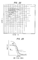
- the value of ⁇ V is detected at a step 190, the conditions ⁇ V > X, X > ⁇ V > Y, and Y > ⁇ V are judged at steps 192 and 194, and Vs is accordingly corrected by ⁇ V S1' ⁇ V S2 or ⁇ V S3 at steps 196, 198 or 200.
- Vs is then stored (steps 202 and 204) in the map (shown in Figure 22) of the set current I B for N-L,
- N 2 and L 2 are detected (step 212), and the value of Vs corresponding to these values of N 2 and L 2 is promptly read out of the map (step 214) and is output (step 216) so that it can be used for the control.
- Figure 23 shows still another embodiment of the present invention in which, when the characteristic of the electromotive force change from that of the solid line to that of the broken line as a result of the increase of ⁇ A/F, the value of ⁇ V corresponding to ⁇ A/F is detected and a coefficient corresponding to this AV is added to the electromotive force to provide the signal shown by the double dot-dash line. If the control is conducted by that signal while the slice level is left at Vs, the same effect as that obtainable when the slice level is lowered is obtained so that the controlled A/F ratio does not change but stays at (A/F) o .
- the circuit construction for this is shown in Figure 24.
- a low frequency component V L is extracted from the output of the sensor portion 20' by a low-pass circuit 40, and the fluctuating high frequency component ⁇ V H is provided by a high-pass circuit 41.
- the summation (V L + ⁇ V H ) is computed by an arithmetic circuit 42 and is applied to the control unit 90 and is used for the control.
- Figure 25 shows a circuit by which the voltage (or current) supplied to the sensor is reduced to zero when the air fuel ratio enters the rich region of ⁇ 1.0 when an air fuel ratio sensor of the oxygen pump type is used. If the voltage is applied to the solid electrolyte when the exhaust gas contains remarkably little oxygen, as in the rich region, the phenomenon arises that the oxygen ions migrate from the solid electrolyte. As a result, even if the air fuel ratio enters again the lean region, it takes some time for the oxygen ions to fill the solid electrolyte, and the sensor is insensitive during that period so that the response is delayed.
- a transistor 51 When the signal V O2 is ON ( ⁇ 1.0) , a transistor 51 is turned on to prevent the flow of current from a power supply 52 to an air fuel ratio sensor 53.
- the signal V 02 When the signal V 02 is OFF ( ⁇ > 1.0), on the other hand, the traniistor 51 is turned off to supply the current to the air fuel ratio sensor 53.
- the signal V O2 is ON but the output from the air fuel ratio sensor 53 is off, a constant voltage is applied in the meantime to a microcomputer 55 from a resistor 54 so as to keep a lean signal generated.
- Figure 26 shows the operations of the circuit of Figure 25.
- Figure 26(a) shows the changes in the CO component of the exhaust gases.
- the current I supplied to the air fuel ratio sensor 53 at this time by the actions of the comparator 50 and the transistor 51 drops to zero, as shown in Figure 2 6(c) .
- the output from the sensor 53 is off only within that rich region, as shown in Figure 26(d).
- the off signal would be an enriching signal during the air fuel ratio control if left as it is, so that the control cannot be conducted because a control toward the lean state could not be provided. Therefore, an ON signal is generated during this time period, as shown in Figure 26(e).
- This leaning signal must be input to the microcomputer 55.
- the signal input to the microcomputer 55 is the sum of the signals of Figure 26(d) and (e), shown in Figure 26(f).
- the current supplied to the sensor 53 is cut by this method, and the air fuel ratio is so controlled that it is promptly returned toward the lean state by the leaning signal which is being generated in the meantime, thereby eliminating the insensitivity and the delay in response when in the rich region.
- the air fuel ratio detector can have a rapid response and can be used for an accurate air fuel ratio control.
Applications Claiming Priority (2)
| Application Number | Priority Date | Filing Date | Title |
|---|---|---|---|
| JP58016037A JPS59142449A (ja) | 1983-02-04 | 1983-02-04 | 空燃比検出装置 |
| JP16037/83 | 1983-02-04 |
Publications (3)
| Publication Number | Publication Date |
|---|---|
| EP0116353A2 true EP0116353A2 (de) | 1984-08-22 |
| EP0116353A3 EP0116353A3 (en) | 1985-08-28 |
| EP0116353B1 EP0116353B1 (de) | 1988-09-21 |
Family
ID=11905381
Family Applications (1)
| Application Number | Title | Priority Date | Filing Date |
|---|---|---|---|
| EP84101116A Expired EP0116353B1 (de) | 1983-02-04 | 1984-02-03 | Verfahren zur Steuerung des Luft-Kraftstoff-Verhältnisses und Luft-Kraftstoff-Verhältnis-Detektor |
Country Status (5)
| Country | Link |
|---|---|
| US (1) | US4534330A (de) |
| EP (1) | EP0116353B1 (de) |
| JP (1) | JPS59142449A (de) |
| KR (1) | KR900005587B1 (de) |
| DE (1) | DE3474192D1 (de) |
Cited By (1)
| Publication number | Priority date | Publication date | Assignee | Title |
|---|---|---|---|---|
| EP0139218A2 (de) * | 1983-09-29 | 1985-05-02 | Nissan Motor Co., Ltd. | Mess system des Luft/Kraftstoffverhältnisses in einem I.B. Motor der eine Sauerstoffsonde gebraucht |
Families Citing this family (21)
| Publication number | Priority date | Publication date | Assignee | Title |
|---|---|---|---|---|
| JP2513458B2 (ja) * | 1985-05-27 | 1996-07-03 | 本田技研工業株式会社 | エンジンの空燃比検出装置 |
| JPH0643981B2 (ja) * | 1985-10-02 | 1994-06-08 | 株式会社日立製作所 | 空燃比制御装置 |
| JPH0727390Y2 (ja) * | 1987-08-19 | 1995-06-21 | 三菱電機株式会社 | 内燃機関の空燃比制御装置 |
| JPS6460744A (en) * | 1987-08-31 | 1989-03-07 | Honda Motor Co Ltd | Air-fuel ratio feedback control method for internal combustion engine |
| JP2624731B2 (ja) * | 1987-12-25 | 1997-06-25 | 株式会社日立製作所 | 空燃比検出装置 |
| JPH03134240A (ja) * | 1989-10-18 | 1991-06-07 | Japan Electron Control Syst Co Ltd | 内燃機関の空燃比フィードバック制御装置 |
| JPH04321740A (ja) * | 1991-04-19 | 1992-11-11 | Mitsubishi Electric Corp | エンジンの空燃比制御装置 |
| US5115639A (en) * | 1991-06-28 | 1992-05-26 | Ford Motor Company | Dual EGO sensor closed loop fuel control |
| US5099647A (en) * | 1991-06-28 | 1992-03-31 | Ford Motor Company | Combined engine air/fuel control and catalyst monitoring |
| US5450749A (en) * | 1993-08-25 | 1995-09-19 | Wci Outdoor Products, Inc. | Gas sampling method and dilution tunnel therefor |
| US5383333A (en) * | 1993-10-06 | 1995-01-24 | Ford Motor Company | Method for biasing a hego sensor in a feedback control system |
| US5379590A (en) * | 1993-10-06 | 1995-01-10 | Ford Motor Company | Air/fuel control system with hego current pumping |
| US5614658A (en) * | 1994-06-30 | 1997-03-25 | Dresser Industries | Exhaust sensor |
| JP3257319B2 (ja) * | 1995-01-30 | 2002-02-18 | トヨタ自動車株式会社 | 空燃比検出装置および方法 |
| JP3757507B2 (ja) * | 1996-12-24 | 2006-03-22 | 株式会社デンソー | 空燃比検出装置 |
| US6082177A (en) * | 1997-09-22 | 2000-07-04 | Snap-On Tools Company | Nitric oxide enhanced response circuit for gas analyzer |
| US6382015B1 (en) * | 1998-06-11 | 2002-05-07 | Toyota Jidosha Kabushiki Kaisha | Air-fuel ratio sensor resistance detecting apparatus |
| DE102006014697A1 (de) * | 2006-03-28 | 2007-10-04 | Robert Bosch Gmbh | Abgassensor |
| DE102011086144A1 (de) * | 2011-11-11 | 2013-05-16 | Robert Bosch Gmbh | Verfahren zur Korrektur von Messwerten eines Sensorelements |
| JP5907345B2 (ja) * | 2012-02-03 | 2016-04-26 | 株式会社デンソー | ガスセンサ制御装置及び内燃機関の制御装置 |
| WO2014118894A1 (ja) * | 2013-01-29 | 2014-08-07 | トヨタ自動車株式会社 | 内燃機関の制御装置 |
Citations (5)
| Publication number | Priority date | Publication date | Assignee | Title |
|---|---|---|---|---|
| DE2554988A1 (de) * | 1975-12-06 | 1977-06-16 | Bosch Gmbh Robert | Verfahren zur bestimmung der zusammensetzung des einer brennkraftmaschine zugefuehrten betriebsgemisches und anwendung des verfahrens zur regelung des gemisches sowie einrichtung zur durchfuehrung des verfahrens |
| US4030349A (en) * | 1976-08-16 | 1977-06-21 | Beckman Instruments, Inc. | Engine analysis apparatus |
| GB1488754A (en) * | 1974-07-24 | 1977-10-12 | Nissan Motor | Electronic fuel injection control unit |
| US4178884A (en) * | 1975-06-05 | 1979-12-18 | Nippondenso Co., Ltd. | Method and system to control the mixture air-to-fuel ratio |
| GB2064828A (en) * | 1979-11-17 | 1981-06-17 | Bosch Gmbh Robert | Regulation of the air-to-fuel ratio of combustible mixture for an engine |
Family Cites Families (11)
| Publication number | Priority date | Publication date | Assignee | Title |
|---|---|---|---|---|
| US4210106A (en) * | 1975-10-13 | 1980-07-01 | Robert Bosch Gmbh | Method and apparatus for regulating a combustible mixture |
| JPS5297030A (en) * | 1976-02-12 | 1977-08-15 | Nissan Motor Co Ltd | Air fuel ratio controller |
| JPS5381827A (en) * | 1976-12-27 | 1978-07-19 | Nissan Motor Co Ltd | Air fuel ratio controller |
| DE2707383C2 (de) * | 1977-02-21 | 1982-12-02 | Robert Bosch Gmbh, 7000 Stuttgart | Verfahren und Vorrichtung zur Überwachung der Betriebsbereitschaft einer Sauerstoffsonde (λ-Sonde) |
| JPS552932A (en) * | 1978-06-22 | 1980-01-10 | Nippon Soken Inc | Air-fuel ratio detector |
| JPS6045744B2 (ja) * | 1978-08-07 | 1985-10-11 | 愛三工業株式会社 | 空燃比制御装置 |
| US4228775A (en) * | 1978-11-17 | 1980-10-21 | General Motors Corporation | Closed loop air/fuel ratio controller with asymmetrical proportional term |
| DE2919194C3 (de) * | 1979-05-12 | 1994-07-28 | Bosch Gmbh Robert | Anordnung zum Regeln der Zusammensetzung des einer Brennkraftmaschine zugeführten Luft-Kraftstoff-Gemischs |
| JPS5623531A (en) * | 1979-08-02 | 1981-03-05 | Fuji Heavy Ind Ltd | Air-fuel ratio controller |
| JPS5744752A (en) * | 1980-09-01 | 1982-03-13 | Toyota Motor Corp | Method of controlling air fuel ratio of internal combustion engine |
| US4337745A (en) * | 1980-09-26 | 1982-07-06 | General Motors Corporation | Closed loop air/fuel ratio control system with oxygen sensor signal compensation |
-
1983
- 1983-02-04 JP JP58016037A patent/JPS59142449A/ja active Granted
-
1984
- 1984-01-31 US US06/575,666 patent/US4534330A/en not_active Expired - Fee Related
- 1984-02-01 KR KR1019840000462A patent/KR900005587B1/ko not_active IP Right Cessation
- 1984-02-03 DE DE8484101116T patent/DE3474192D1/de not_active Expired
- 1984-02-03 EP EP84101116A patent/EP0116353B1/de not_active Expired
Patent Citations (5)
| Publication number | Priority date | Publication date | Assignee | Title |
|---|---|---|---|---|
| GB1488754A (en) * | 1974-07-24 | 1977-10-12 | Nissan Motor | Electronic fuel injection control unit |
| US4178884A (en) * | 1975-06-05 | 1979-12-18 | Nippondenso Co., Ltd. | Method and system to control the mixture air-to-fuel ratio |
| DE2554988A1 (de) * | 1975-12-06 | 1977-06-16 | Bosch Gmbh Robert | Verfahren zur bestimmung der zusammensetzung des einer brennkraftmaschine zugefuehrten betriebsgemisches und anwendung des verfahrens zur regelung des gemisches sowie einrichtung zur durchfuehrung des verfahrens |
| US4030349A (en) * | 1976-08-16 | 1977-06-21 | Beckman Instruments, Inc. | Engine analysis apparatus |
| GB2064828A (en) * | 1979-11-17 | 1981-06-17 | Bosch Gmbh Robert | Regulation of the air-to-fuel ratio of combustible mixture for an engine |
Cited By (2)
| Publication number | Priority date | Publication date | Assignee | Title |
|---|---|---|---|---|
| EP0139218A2 (de) * | 1983-09-29 | 1985-05-02 | Nissan Motor Co., Ltd. | Mess system des Luft/Kraftstoffverhältnisses in einem I.B. Motor der eine Sauerstoffsonde gebraucht |
| EP0139218A3 (en) * | 1983-09-29 | 1986-08-27 | Nissan Motor Co., Ltd. | Air/fuel ratio monitoring system in ic engine using oxygen sensor |
Also Published As
| Publication number | Publication date |
|---|---|
| KR900005587B1 (ko) | 1990-07-31 |
| US4534330A (en) | 1985-08-13 |
| JPS59142449A (ja) | 1984-08-15 |
| EP0116353A3 (en) | 1985-08-28 |
| JPH049259B2 (de) | 1992-02-19 |
| EP0116353B1 (de) | 1988-09-21 |
| DE3474192D1 (en) | 1988-10-27 |
| KR840009135A (ko) | 1984-12-24 |
Similar Documents
| Publication | Publication Date | Title |
|---|---|---|
| US4534330A (en) | Air/fuel ratio detector | |
| US6383354B1 (en) | Gas concentration sensing apparatus | |
| US6295862B1 (en) | Gas concentration measuring apparatus compensating for error component of output signal | |
| US4905652A (en) | Device for measuring a component of a gaseous mixture | |
| EP0173157B1 (de) | Fühler des Luft-Brennstoff-Verhältnisses | |
| US6901785B2 (en) | Gas concentration measuring apparatus designed to minimize measurement error | |
| US9470654B2 (en) | System and method for updating a baseline output of a gas sensor | |
| US6226861B1 (en) | Method and apparatus for gas concentration detection and manufacturing method of the apparatus | |
| US4170965A (en) | Compensation for inherent fluctuation in output level of exhaust sensor in air-fuel ratio control system for internal combustion engine | |
| US4120269A (en) | Compensation for inherent fluctuation in output level of exhaust sensor in air-fuel ratio control system for internal combustion engine | |
| EP0984275B1 (de) | Vorrichtung zum Fühlen einer Gaskonzentration mit Unterdrückung von Spannungsschwingungen des Fühlers | |
| US4882030A (en) | Air-fuel ratio detection system for engine exhaust gas | |
| US4915813A (en) | Oxygen concentration detecting device | |
| US5396875A (en) | Air/fuel control with adaptively learned reference | |
| US5265458A (en) | Method of compensating output of air/fuel ratio sensor for variation in the current sensitivity to oxygen | |
| US4233033A (en) | Method and apparatus for measuring the O2 content of a gas | |
| US4566419A (en) | Apparatus and method for controlling air-to-fuel ratio for an internal combustion engine | |
| US4748953A (en) | Air/fuel ratio control apparatus for internal combustion engines | |
| US5383333A (en) | Method for biasing a hego sensor in a feedback control system | |
| US4553424A (en) | Method for detecting an oxygen concentration and a method for controlling an air-to-fuel ratio based on the detected oxygen concentration | |
| JP3736921B2 (ja) | 空燃比センサ | |
| US4716760A (en) | Air-fuel ratio detection system | |
| US5379590A (en) | Air/fuel control system with hego current pumping | |
| US4548179A (en) | Air-fuel ratio control system | |
| US5580440A (en) | Air fuel ratio sensory |
Legal Events
| Date | Code | Title | Description |
|---|---|---|---|
| PUAI | Public reference made under article 153(3) epc to a published international application that has entered the european phase |
Free format text: ORIGINAL CODE: 0009012 |
|
| 17P | Request for examination filed |
Effective date: 19840207 |
|
| AK | Designated contracting states |
Designated state(s): DE FR GB IT |
|
| PUAL | Search report despatched |
Free format text: ORIGINAL CODE: 0009013 |
|
| AK | Designated contracting states |
Designated state(s): DE FR GB IT |
|
| 17Q | First examination report despatched |
Effective date: 19870428 |
|
| GRAA | (expected) grant |
Free format text: ORIGINAL CODE: 0009210 |
|
| AK | Designated contracting states |
Kind code of ref document: B1 Designated state(s): DE FR GB IT |
|
| REF | Corresponds to: |
Ref document number: 3474192 Country of ref document: DE Date of ref document: 19881027 |
|
| ET | Fr: translation filed | ||
| ITF | It: translation for a ep patent filed |
Owner name: MODIANO & ASSOCIATI S.R.L. |
|
| ITTA | It: last paid annual fee | ||
| PLBE | No opposition filed within time limit |
Free format text: ORIGINAL CODE: 0009261 |
|
| STAA | Information on the status of an ep patent application or granted ep patent |
Free format text: STATUS: NO OPPOSITION FILED WITHIN TIME LIMIT |
|
| 26N | No opposition filed | ||
| PGFP | Annual fee paid to national office [announced via postgrant information from national office to epo] |
Ref country code: DE Payment date: 19940428 Year of fee payment: 11 |
|
| PG25 | Lapsed in a contracting state [announced via postgrant information from national office to epo] |
Ref country code: DE Effective date: 19951101 |
|
| PGFP | Annual fee paid to national office [announced via postgrant information from national office to epo] |
Ref country code: FR Payment date: 19980116 Year of fee payment: 15 |
|
| PGFP | Annual fee paid to national office [announced via postgrant information from national office to epo] |
Ref country code: GB Payment date: 19980123 Year of fee payment: 15 |
|
| PG25 | Lapsed in a contracting state [announced via postgrant information from national office to epo] |
Ref country code: GB Free format text: LAPSE BECAUSE OF NON-PAYMENT OF DUE FEES Effective date: 19990203 |
|
| GBPC | Gb: european patent ceased through non-payment of renewal fee |
Effective date: 19990203 |
|
| PG25 | Lapsed in a contracting state [announced via postgrant information from national office to epo] |
Ref country code: FR Free format text: LAPSE BECAUSE OF NON-PAYMENT OF DUE FEES Effective date: 19991029 |
|
| REG | Reference to a national code |
Ref country code: FR Ref legal event code: ST |