US4748953A - Air/fuel ratio control apparatus for internal combustion engines - Google Patents

Air/fuel ratio control apparatus for internal combustion engines Download PDF

Info

Publication number
US4748953A
US4748953A US06/932,375 US93237586A US4748953A US 4748953 A US4748953 A US 4748953A US 93237586 A US93237586 A US 93237586A US 4748953 A US4748953 A US 4748953A
Authority
US
United States
Prior art keywords
air
fuel ratio
proportional
control
integration
Prior art date
Legal status (The legal status is an assumption and is not a legal conclusion. Google has not performed a legal analysis and makes no representation as to the accuracy of the status listed.)
Expired - Lifetime
Application number
US06/932,375
Inventor
Minoru Osuga
Yoshishige Oyama
Current Assignee (The listed assignees may be inaccurate. Google has not performed a legal analysis and makes no representation or warranty as to the accuracy of the list.)
Hitachi Ltd
Original Assignee
Hitachi Ltd
Priority date (The priority date is an assumption and is not a legal conclusion. Google has not performed a legal analysis and makes no representation as to the accuracy of the date listed.)
Filing date
Publication date
Application filed by Hitachi Ltd filed Critical Hitachi Ltd
Assigned to HITACHI, LTD., A CORP OF JAPAN reassignment HITACHI, LTD., A CORP OF JAPAN ASSIGNMENT OF ASSIGNORS INTEREST. Assignors: OSUGA, MINORU, OYAMA, YOSHISHIGE
Application granted granted Critical
Publication of US4748953A publication Critical patent/US4748953A/en
Anticipated expiration legal-status Critical
Expired - Lifetime legal-status Critical Current

Links

Images

Classifications

    • FMECHANICAL ENGINEERING; LIGHTING; HEATING; WEAPONS; BLASTING
    • F02COMBUSTION ENGINES; HOT-GAS OR COMBUSTION-PRODUCT ENGINE PLANTS
    • F02DCONTROLLING COMBUSTION ENGINES
    • F02D41/00Electrical control of supply of combustible mixture or its constituents
    • F02D41/02Circuit arrangements for generating control signals
    • F02D41/14Introducing closed-loop corrections
    • F02D41/1438Introducing closed-loop corrections using means for determining characteristics of the combustion gases; Sensors therefor
    • F02D41/1477Introducing closed-loop corrections using means for determining characteristics of the combustion gases; Sensors therefor characterised by the regulation circuit or part of it,(e.g. comparator, PI regulator, output)
    • F02D41/1483Proportional component
    • FMECHANICAL ENGINEERING; LIGHTING; HEATING; WEAPONS; BLASTING
    • F02COMBUSTION ENGINES; HOT-GAS OR COMBUSTION-PRODUCT ENGINE PLANTS
    • F02DCONTROLLING COMBUSTION ENGINES
    • F02D41/00Electrical control of supply of combustible mixture or its constituents
    • F02D41/02Circuit arrangements for generating control signals
    • F02D41/14Introducing closed-loop corrections
    • F02D41/1438Introducing closed-loop corrections using means for determining characteristics of the combustion gases; Sensors therefor
    • F02D41/1477Introducing closed-loop corrections using means for determining characteristics of the combustion gases; Sensors therefor characterised by the regulation circuit or part of it,(e.g. comparator, PI regulator, output)
    • F02D41/1479Using a comparator with variable reference
    • FMECHANICAL ENGINEERING; LIGHTING; HEATING; WEAPONS; BLASTING
    • F02COMBUSTION ENGINES; HOT-GAS OR COMBUSTION-PRODUCT ENGINE PLANTS
    • F02DCONTROLLING COMBUSTION ENGINES
    • F02D41/00Electrical control of supply of combustible mixture or its constituents
    • F02D41/02Circuit arrangements for generating control signals
    • F02D41/14Introducing closed-loop corrections
    • F02D41/1438Introducing closed-loop corrections using means for determining characteristics of the combustion gases; Sensors therefor
    • F02D41/1444Introducing closed-loop corrections using means for determining characteristics of the combustion gases; Sensors therefor characterised by the characteristics of the combustion gases
    • F02D41/1454Introducing closed-loop corrections using means for determining characteristics of the combustion gases; Sensors therefor characterised by the characteristics of the combustion gases the characteristics being an oxygen content or concentration or the air-fuel ratio
    • F02D41/1456Introducing closed-loop corrections using means for determining characteristics of the combustion gases; Sensors therefor characterised by the characteristics of the combustion gases the characteristics being an oxygen content or concentration or the air-fuel ratio with sensor output signal being linear or quasi-linear with the concentration of oxygen

Definitions

  • This invention relates to an air/fuel ratio control apparatus for internal combustion engines.
  • an air/fuel ratio control apparatus uses a conventional oxygen sensor, the output signal of which changes stepwise between upper and lower levels at an air/fuel ratio ⁇ equal to one (stoichiometric air/fuel ratio), as described in JP-A-51-106828. Accordingly, if the conventional air/fuel ratio control apparatus is employed with another type of air/fuel ratio sensor whose output changes in proportion to the air/fuel ratio, the control system will operate erroneously. More particularly, in the sensor producing an output signal proportional to the air/fuel ratio, the gain relative to the air/fuel ratio is smaller in the lean region and larger in the rich region. Therefore, if the proportional constant of the control system, for example, remains unchanged throughout the rich and lean regions, an erroneous operation, such as hunting, will result within either one of the rich and lean regions.
  • An object of this invention is to provide an air/fuel ratio control apparatus which can use a sensor of the type which provides an output signal proportional to the air/fuel ratio without causing hunting and the like.
  • This invention features that, with use of a sensor producing a proportional detection signal, the propotional or integration constant of a proportional or integration circuit of the air/fuel ratio control system is changed in compliance with a set control value of air/fuel ratio.
  • FIG. 1 is a schematic block diagram showing the overall construction of an air/fuel ratio control apparatus according to an embodiment of the invention
  • FIG. 2 is a graph showing a sensor output characteristic
  • FIG. 3 is a sectional view showing the construction of an air/fuel ratio sensor
  • FIGS. 4A, 4B, 5, 6, and 7 are illustrative of the principle of one type of air/fuel ratio sensor
  • FIG. 8 is a graph showing a characteristic of the sensor of FIGS. 4 to 7;
  • FIG. 9 is illustrative of the principle of another type of sensor.
  • FIG. 10 graphically illustrates a characteristic of the FIG. 9 sensor
  • FIG. 11 is a graph showing various characteristics of the sensor
  • FIGS. 12(a), 12(b), 12(c), 13, 14(a) and 14(b) are graphs showing closed loop control of the air/fuel ratio and closed loop control characteristics
  • FIG. 15 is a block diagram of an air/fuel ratio closed loop control system
  • FIG. 16 is a diagram showing signal waveforms appearing in the system of FIG. 15;
  • FIG. 17 is a circuit diagram for implementation of the FIG. 15 system according to an embodiment of the invention.
  • FIG. 18 is a circuit diagram showing a modification of part of the FIG. 17 circuit
  • FIG. 19 is a flow chart for implementation of the FIG. 15 system according to another embodiment of the invention.
  • FIG. 20 illustrates map data used in the FIG. 19 embodiment
  • FIG. 21 is a graph showing actual output characteristics of the air/fuel ratio sensor
  • FIG. 22 is a circuit diagram for implementation of the FIG. 15 system according to further embodiment of the invention.
  • FIG. 23 is a graph showing the ideal relation between the gain of air/fuel ratio sensor and the proportional gain.
  • the apparatus comprises a fuel feeder 1 for feeding fuel to an engine 2, and an air/fuel ratio sensor 4 mounted in an exhaust pipe 3.
  • a drive circuit 5 for the sensor 4 transmits a signal proportional to an air/fuel ratio.
  • a difference generator 6 determines a difference between a set value and a detected value, and the difference is applied to a proportional circuit 7 and an integration circuit 8.
  • a control signal generator 9 is responsive to output signals from the proportional circuit 7 and integration circuit 8 to generate and output a control signal to the fuel feeder 1 such as an electronic fuel injection valve.
  • the control apparatus of the above construction is well adapted to implement proportional and integration closed loop control of the air/fuel ratio. This apparatus may otherwise be used with a differentiation control system to perform PID control.
  • the air/fuel ratio sensor 4 has different output gains relative to air/fuel ratio ⁇ for a lean region where ⁇ >1.0 and for a rich region where ⁇ 1.0, the proportional constant of proportional circuit 7 and the integration constant of integration circuit 8 for closed loop control at a point A within the lean region must be changed from those for closed control at a point B within the rich region.
  • the proportional control system is predominant in the closed loop control and so stability of the closed loop control system is greatly affected by changes in the proportional constant. Therefore, the apparatus of FIG. 1 further comprises a control constant modifier 10 adapted to issue commands which change the control constant of the proportional circuit 7 mainly and also the control constant of the integration circuit 8 in compliance with a set control value of air/fuel ratio.
  • the air/fuel ratio sensor 4 is constructed as shown in FIG. 3, having a solid electrolyte 11, a diffusion resistor 12 of a porous material, a heater 13 for heating the solid electrolyte 11, and a protective tube 14.
  • a solid electrolyte 11 having ability to conduct oxygen ions is heated to about 600° to 1000° C. by means of the heater 13 and current or voltage is supplied to electrodes provided, as will be described later, on the opposite side surfaces of solid electrolyte 11, an amount of oxygen, which is proportional to amounts of electricity supplied to the opposite side surfaces, propagates through the solid electrolyte 11.
  • the amount of oxygen prevailing in the diffusion resistor 12 is then controlled by utilizing this oxygen pumping effect such that the partial pressure of oxygen inside the diffusion resistor 12 is always constant. Then, the amounts of electricity consumed to establish the constant oxygen partial pressure are in proportion to an air/fuel ratio.
  • atmospheric air is admitted to the interior side surface and an exhaust gas is admitted to the exterior side surface.
  • FIG. 4 is illustrative of the principle of air/fuel ratio detection.
  • an encircled portion in FIG. 3 is enlarged for illustration at (a) in FIG. 4.
  • An electrode 15a is provided on a side surface exposed to atmosphere and an electrode 15b is provided on the opposite side surface exposed to the exhaust gas.
  • an electromotive force E developing in the solid electrolyte 11 is measured. By measuring this E, the oxygen partial pressure inside the diffusion resistor 12 can be measured.
  • this amount of propagating oxygen is determined by amounts of electricity supplied to the opposite side surfaces, which amounts are in turn proportional to an air/fuel ratio under measurement and set for controlling.
  • the amount of oxygen inside the diffusion resistor 12 is controlled as shown at section (b) in FIG. 4.
  • the electrode 15b is applied with a fixed voltage V P through a buffer amplifier 16 and the electrode 15a is applied with a voltage V D through a buffer amplifier 17.
  • V D >V P is established by changing the voltage V D , a current I is passed in a direction of solid arrow and the oxygen O 2 in the diffusion resistor 12 is consequently discharged in a direction of solid arrow.
  • the amount of oxygen inside the diffusion resistor 12 is decreased.
  • V D is decreased to establish V D ⁇ V P
  • a current I is passed in a direction of dotted arrow and the oxygen O 2 is charged in a direction of dotted arrow, thus increasing the amount of oxygen inside the diffusion resistor 12.
  • E the electromotive force representative of the partial pressure of oxygen within the diffusion resistor 12 can be controlled so as to be always constant.
  • the measurement of E and the application of the voltage V D are alternately effected on a time division basis. The alternate operations are accomplished for the lean region as illustrated in the timing chart of FIG. 5 wherein V D >V P is established during a period for the application of V D to obtain the constant electromotive force E.
  • V D ⁇ V P is established to obtain the constant electromotive force E as illustrated in the timing chart of FIG. 6.
  • the level of V D settled for the constant E is in proportion to a set control value of air/fuel ratio.
  • an electromotive force E is measured by opening switches 19a and 19b and closing switches 18a and 18b under the direction of a controller 80, so that E is held by a circuit comprised of an amplifier 20.
  • a differential integration circuit comprised of an amplifier 21 compares the measured E with a reference voltage E ref (constant) and then integrates the difference between the E and E ref to increase or decrease the voltage V D in accordance with a time constant. Specifically, for E>E ref , the voltage V D is decreased and for E ⁇ E ref , increased.
  • the thus varied voltage V D is applied to the solid electrolyte 11 by opening the switches 18a and 18b and closing the switches 19a and 19b.
  • the voltage V D is controlled for increase or decrease to always make the value of E equal to E ref and hence it is placed in proportion to an air/fuel ratio under measurement.
  • the voltage V D is held by a hold circuit comprised of an amplifier 22 and is delivered as an output signal V out .
  • the output signal V out is related to the air/fuel ratio ⁇ as graphically illustrated in FIG. 8.
  • the value of V out is subject to gains which are different for the rich and lean regions. In particular, the sensor is more sensitive in the rich region and less sensitive in the lean region.
  • FIG. 9 The arrangement of FIG. 9 includes solid electrolytes 23 and 24, a diffusion hole 25 and a chamber 26.
  • a fixed current I B is supplied to the solid electrolyte 24 in a direction of the arrow, oxygen O 2 in the atmosphere is charged into the chamber 26.
  • V S a fixed voltage
  • the diffusion hole 25 functions to generate a so-called marginal current I S which is proportional to an amount of oxygen inside the chamber 26.
  • I S takes a value which is proportional to the sum of an amount of oxygen charged by I B and an amount of oxygen contained in exhaust gas diffusing into the chamber through the diffusion hole 25.
  • I B In the rich region, the oxygen charged by I B is consumed by a combustible gas of CO, HC and H 2 diffusing into the chamber 26 and I S takes a value which is proportional to an amount of the remaining oxygen. As the air/fuel ratio ⁇ falls below 1.0 with the content of the combustible gas increased, the value of I S decreases.
  • the output signal V out corresponding to I S is related to the air/fuel ratio ⁇ as graphically illustrated in FIG. 10.
  • I B is a positive fixed value
  • a characteristic curve (b) is obtained, indicating that the measurement of the air/fuel ratio can be permitted over a wide range.
  • the value of V out is subject to gains relative to ⁇ which are different for the rich and lean regions.
  • the oxygen partial pressure, P O2 increases as the air/fuel ratio ⁇ increases, causing the V out to increase.
  • the partial pressure of CO, HC and H 2 combustible gas, P CO +P HC +P H2 increases as the ⁇ decreases, causing the V out to decrease.
  • the gain is different from that for the lean region to deviate from a dotted-line extension (a) because a constituent H 2 gas has 3 to 4 times the diffusion speed of the remaining gas O 2 , CO or HC and consumes a great amount of oxygen charged into the diffusion resistor through the solid electrolyte. Therefore, the gain K R for the rich region becomes larger than the gain K L for the lean region.
  • This invention contemplates improvements in air/fuel ratio control based on the sensor having sensitivity which, as has been explained hereinbefore, is different for the rich and lean regions.
  • FIG. 12 illustrates at section (a) a control signal for controlling the amount of fuel. Since combustion conditions in the engine slightly vary even under normal operation, the control signal also varies slightly as indicated at (a) in FIG. 12 to correct a variation in combustion. FIG. 12 also indicates at (a) that values of the proportional and integration constants remain unchanged throughout the lean and rich regions. In such a case, owing to the different gains devoted to V out , an erroneous operation takes place in either one of the lean and rich regions.
  • control constants are set to meet the conditions of the lean region, then controlling with the same control constants will lead to too high a proportional gain in the rich region and hunting will result as shown at (b) in FIG. 12. Even without the occurrence of hunting, the ultimate air/fuel ratio will deviate from a commanded air/fuel ratio by a stationary difference e in the rich region as indicated at (c) in FIG. 12. To solve the above problems, it is necessary to change the control constants such that they meet the conditions of both the rich and lean regions.
  • the proportional gain is varied complementarily to the different gains K R and K L shown in FIG. 13, that is, made smaller for the rich region than for the lean region as shown at (a) in FIG. 14.
  • the varying proportional gain By using the varying proportional gain, the ultimate air/fuel ratio freed from hunting or stationary difference e can be obtained even in the rich region as shown at (b) in FIG. 14.
  • the integration constant needs to be varied for the rich and lean regions.
  • the proportional and integration control system is generally and schematically illustrated for clarity of explanation in a block diagram of FIG. 15.
  • an engine 30 illustrated as a block includes a fuel feed system and is controlled in terms of air/fuel ratio.
  • a circuit 27 for deriving and producing a difference a has a proportional gain of K 1 . This difference is multiplied by a constant gain K 2 at a block 28 to prepare a proportional component b of the control signal.
  • the difference a is also integrated at a block 29 to prepare an integration component c of the control signal.
  • the integration component is added to the input signal to remove an offset.
  • this signal is processed into a difference which in turn is multiplied by the gain K 1 to provide the difference signal a as indicated at (b) in FIG. 16.
  • the difference signal a is further multiplied by the gain K 2 to provide the signal b as indicated at (c) in FIG. 16.
  • the difference signal a is also integrated with a time constant T I to provide the signal c as indicated at (d) in FIG. 16.
  • the proportional signal b and the integration signal c are added together to provide a signal d as indicated at (e) in FIG. 16. If the proportional gain K 2 of block 28 is decreased, the signal b is decreased as indicated by a dotted line at (c) in FIG.
  • FIG. 17 illustrates, in block form, an embodiment of a circuit for implementation of the FIG. 15 control system.
  • a difference circuit C 1 produces a difference between the output signal V out and a voltage V ref which is the sum of a commanded value and a fixed value.
  • the output signal of the difference circuit C 1 is multiplied by the proportional gain K 2 at an amplifier circuit C 2 .
  • This amplifier circuit C 2 produces an amplified signal which contains an amplified AC component and an amplified DC component and so, the amplified DC component (V ref ") is subtracted at a subtraction circuit C 3 to provide a difference signal representative of deviation from the commanded value and which is multiplied by the proportional gain K 2 .
  • the output signal of the difference circuit C 1 is also supplied to a differential integration circuit C 4 so as to be compared with a voltage V ref ' corresponding to the commanded value, so that an integrated signal in accordance with a difference representative of deviation from the commanded value is delivered out of the differential integration circuit C 4 .
  • the integrated signal is increasing when the output signal of the difference circuit C 1 is larger than the V ref ' and is decreasing when the output signal is smaller than the V ref ', indicating that correct integration operations are being carried out.
  • the proportional constant and the integration constant can be varied as will be described below. Since the proportional constant is defined by a resistance ratio between resistances of resistors R 1 and R 2 included in the amplifier circuit C 2 , the proportional constant can be varied by turning on or off a switch S 1 to connect or disconnect a resistor R 3 in parallel relationship with the resistor R 2 .
  • the switch S 1 is operated by a command from the control constant modifier 10.
  • the integration constant defined by resistances of resistors R 4 and R 5 and capacitances of capacitors C 10 and C 11 of the integration circuit C 4 , can be varied by turning on or off a switch S 2 to connect or disconnect a resistor R 6 in parallel relationship with the resistor R 4 and by turning on or off a switch S 3 to connect or disconnect a resistor R 7 in parallel relationship with the resistor R 5 .
  • These switches S 2 and S 3 are also operated by commands from the control constant modifier 10.
  • control constants can be varied to meet an air/fuel ratio to be controlled.
  • the integration constant of the integration circuit C 4 may also be varied using a modified circuit as shown in FIG. 18.
  • the integration constant can be varied by turning on or off a switch S 4 to connect or disconnect a capacitor C 12 in parallel relationship with the capacitor C 10 and by turning on or off a switch S 5 to connect or disconnect a capacitor C 13 in parallel relationship with the capacitor C 11 .
  • These switches S 4 and S 5 are again operated by commands issued from the control constant modifier 10.
  • the proportional and integration control can be performed and the control constants therefor can be varied using a microcomputer in accordance with a flow chart as illustrated in FIG. 19.
  • a commanded air/fuel ratio ⁇ to be controlled is first read out of a map graphically illustrated in FIG. 20 as indicated at a step 100.
  • An output value V out* of the air/fuel ratio sensor corresponding to the commanded ⁇ is then set as indicated at a step 200.
  • the output value V out* is compared with a value V out1 in a step 300 and when V out* exceeds V out1 , the proportional constant is set to K P in a step 400 and the integration constant is set to K I in a step 500. If it is decided in a step 600 that V out* falls within a range V out1 >V out* ⁇ V out2 , the preset proportional constant K P is incremented by ⁇ K P in a step 700 and the present integration constant K I is incremented by ⁇ K I in a step 800.
  • step 900 If it is decided in a step 900 that V out* falls within a range V out2 >V out* ⁇ V out3 , the preset proportional constant K P is further incremented by ⁇ K P ' in a step 1000 and the preset integration constant K I is further incremented by ⁇ K I ' in a step 1100. The above operations are repeated to obtain optimum control constants which meet the air/fuel ratio to be controlled.
  • V out versus air/fuel ratio characteristic plotted by measuring engine exhaust gas. Since the partial pressures P O2 and P CO +P HC +P H2 change curvedly with respect to the air/fuel ratio, V out also changes curvedly. In other words, V out is subject to gains relative to the air/fuel ratio which not only change at the boundary between the rich and lean regions but also slightly vary in the lean region itself and in the rich region itself. Under the situation, it is ideal that the control constants should be varied continuously or in analog fashion with respect to changes in the air/fuel ratio to be controlled.
  • FIG. 22 shows a circuit arrangement to this end.
  • a transistor T r1 is connected to substitute for the resistor R 2 included in the amplifier circuit C 2 of FIG. 17.
  • the resistance of the transistor T r1 is varied in analog fashion with the value of a voltage V 3 applied to its base and the proportional constant consequently varies in analog fashion.
  • transistors T r2 and T r3 are connected to substitute for the resistors R 4 and R 5 included in the integration circuit C 4 of FIG. 17.
  • the resistances of the transistors T r2 and T r3 are varied in analog fashion with values of voltages V 1 and V 2 applied to their bases and hence the integration constant of the integration circuit C 4 varies in analog fashion.
  • a voltage generator 30 responds to commands from the control constant modifier 10 to generate the voltages V 1 , V 2 and V 3 and to change their levels in accordance with an air/fuel ratio set for controlling. If the voltages V 1 , V 2 and V 3 are controlled to proportionate the V out , exact analog operations can be performed.
  • the V out is subject to gains relative to the air/fuel ratio which vary curvedly in analog fashion so as to be larger in the rich region than in the lean region and therefore, it is ideal that the proportional gain should be varied complementarily to the V out to trace an analog curve which is of smaller values in the rich region than in the lean region.
  • the proportional gain can be varied to comply with the analog curve of FIG. 23 by making use of changes in resistance of the transistor used in the circuit of FIG. 22.

Abstract

In feedback control for the air/fuel ratio based on a sensor producing an output signal proportional to a change in the air/fuel ratio, a control constant modifier is operative to vary the proportional component and the integration component in a feedback system in accordance with an air/fuel ratio set for controlling, thereby assuring stability of ultimate fuel control.

Description

BACKGROUND OF THE INVENTION
This invention relates to an air/fuel ratio control apparatus for internal combustion engines.
Conventionally, an air/fuel ratio control apparatus uses a conventional oxygen sensor, the output signal of which changes stepwise between upper and lower levels at an air/fuel ratio λ equal to one (stoichiometric air/fuel ratio), as described in JP-A-51-106828. Accordingly, if the conventional air/fuel ratio control apparatus is employed with another type of air/fuel ratio sensor whose output changes in proportion to the air/fuel ratio, the control system will operate erroneously. More particularly, in the sensor producing an output signal proportional to the air/fuel ratio, the gain relative to the air/fuel ratio is smaller in the lean region and larger in the rich region. Therefore, if the proportional constant of the control system, for example, remains unchanged throughout the rich and lean regions, an erroneous operation, such as hunting, will result within either one of the rich and lean regions.
SUMMARY OF THE INVENTION
An object of this invention is to provide an air/fuel ratio control apparatus which can use a sensor of the type which provides an output signal proportional to the air/fuel ratio without causing hunting and the like.
This invention features that, with use of a sensor producing a proportional detection signal, the propotional or integration constant of a proportional or integration circuit of the air/fuel ratio control system is changed in compliance with a set control value of air/fuel ratio.
BRIEF DESCRIPTION OF THE DRAWINGS
FIG. 1 is a schematic block diagram showing the overall construction of an air/fuel ratio control apparatus according to an embodiment of the invention;
FIG. 2 is a graph showing a sensor output characteristic;
FIG. 3 is a sectional view showing the construction of an air/fuel ratio sensor;
FIGS. 4A, 4B, 5, 6, and 7 are illustrative of the principle of one type of air/fuel ratio sensor;
FIG. 8 is a graph showing a characteristic of the sensor of FIGS. 4 to 7;
FIG. 9 is illustrative of the principle of another type of sensor;
FIG. 10 graphically illustrates a characteristic of the FIG. 9 sensor;
FIG. 11 is a graph showing various characteristics of the sensor;
FIGS. 12(a), 12(b), 12(c), 13, 14(a) and 14(b) are graphs showing closed loop control of the air/fuel ratio and closed loop control characteristics;
FIG. 15 is a block diagram of an air/fuel ratio closed loop control system;
FIG. 16 is a diagram showing signal waveforms appearing in the system of FIG. 15;
FIG. 17 is a circuit diagram for implementation of the FIG. 15 system according to an embodiment of the invention;
FIG. 18 is a circuit diagram showing a modification of part of the FIG. 17 circuit;
FIG. 19 is a flow chart for implementation of the FIG. 15 system according to another embodiment of the invention;
FIG. 20 illustrates map data used in the FIG. 19 embodiment;
FIG. 21 is a graph showing actual output characteristics of the air/fuel ratio sensor;
FIG. 22 is a circuit diagram for implementation of the FIG. 15 system according to further embodiment of the invention; and
FIG. 23 is a graph showing the ideal relation between the gain of air/fuel ratio sensor and the proportional gain.
DESCRIPTION OF THE PREFERRED EMBODIMENTS
Referring now to FIG. 1, there is illustrated, in block form, an air/fuel ratio control apparatus embodying the invention. The apparatus comprises a fuel feeder 1 for feeding fuel to an engine 2, and an air/fuel ratio sensor 4 mounted in an exhaust pipe 3. A drive circuit 5 for the sensor 4 transmits a signal proportional to an air/fuel ratio. Based on this signal, a difference generator 6 determines a difference between a set value and a detected value, and the difference is applied to a proportional circuit 7 and an integration circuit 8. A control signal generator 9 is responsive to output signals from the proportional circuit 7 and integration circuit 8 to generate and output a control signal to the fuel feeder 1 such as an electronic fuel injection valve. Thus, the control apparatus of the above construction is well adapted to implement proportional and integration closed loop control of the air/fuel ratio. This apparatus may otherwise be used with a differentiation control system to perform PID control.
Since, as shown in FIG. 2, the air/fuel ratio sensor 4 has different output gains relative to air/fuel ratio λ for a lean region where λ>1.0 and for a rich region where λ<1.0, the proportional constant of proportional circuit 7 and the integration constant of integration circuit 8 for closed loop control at a point A within the lean region must be changed from those for closed control at a point B within the rich region. Especially, the proportional control system is predominant in the closed loop control and so stability of the closed loop control system is greatly affected by changes in the proportional constant. Therefore, the apparatus of FIG. 1 further comprises a control constant modifier 10 adapted to issue commands which change the control constant of the proportional circuit 7 mainly and also the control constant of the integration circuit 8 in compliance with a set control value of air/fuel ratio.
Components of the apparatus shown in FIG. 1 will now be described in greater detail.
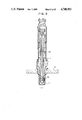
The air/fuel ratio sensor 4 is constructed as shown in FIG. 3, having a solid electrolyte 11, a diffusion resistor 12 of a porous material, a heater 13 for heating the solid electrolyte 11, and a protective tube 14. When the solid electrolyte 11 having ability to conduct oxygen ions is heated to about 600° to 1000° C. by means of the heater 13 and current or voltage is supplied to electrodes provided, as will be described later, on the opposite side surfaces of solid electrolyte 11, an amount of oxygen, which is proportional to amounts of electricity supplied to the opposite side surfaces, propagates through the solid electrolyte 11. The amount of oxygen prevailing in the diffusion resistor 12 is then controlled by utilizing this oxygen pumping effect such that the partial pressure of oxygen inside the diffusion resistor 12 is always constant. Then, the amounts of electricity consumed to establish the constant oxygen partial pressure are in proportion to an air/fuel ratio. In the solid electrolyte 11, atmospheric air is admitted to the interior side surface and an exhaust gas is admitted to the exterior side surface.
FIG. 4 is illustrative of the principle of air/fuel ratio detection. In particular, an encircled portion in FIG. 3 is enlarged for illustration at (a) in FIG. 4. An electrode 15a is provided on a side surface exposed to atmosphere and an electrode 15b is provided on the opposite side surface exposed to the exhaust gas. As is seen at (a) in FIG. 4, an electromotive force E developing in the solid electrolyte 11 is measured. By measuring this E, the oxygen partial pressure inside the diffusion resistor 12 can be measured. More specifically, when an amount of oxygen is charged into or discharged from the interior of the diffusion resistor 12 so as to keep constant the E representative of the oxygen partial pressure, this amount of propagating oxygen is determined by amounts of electricity supplied to the opposite side surfaces, which amounts are in turn proportional to an air/fuel ratio under measurement and set for controlling. The amount of oxygen inside the diffusion resistor 12 is controlled as shown at section (b) in FIG. 4. The electrode 15b is applied with a fixed voltage VP through a buffer amplifier 16 and the electrode 15a is applied with a voltage VD through a buffer amplifier 17. When VD >VP is established by changing the voltage VD, a current I is passed in a direction of solid arrow and the oxygen O2 in the diffusion resistor 12 is consequently discharged in a direction of solid arrow. As a result, the amount of oxygen inside the diffusion resistor 12 is decreased. When the voltage VD is decreased to establish VD <VP, a current I is passed in a direction of dotted arrow and the oxygen O2 is charged in a direction of dotted arrow, thus increasing the amount of oxygen inside the diffusion resistor 12. In this way, the electromotive force E representative of the partial pressure of oxygen within the diffusion resistor 12 can be controlled so as to be always constant. The measurement of E and the application of the voltage VD are alternately effected on a time division basis. The alternate operations are accomplished for the lean region as illustrated in the timing chart of FIG. 5 wherein VD >VP is established during a period for the application of VD to obtain the constant electromotive force E. For the rich region, VD <VP is established to obtain the constant electromotive force E as illustrated in the timing chart of FIG. 6. In FIGS. 5 and 6, the level of VD settled for the constant E is in proportion to a set control value of air/fuel ratio.
The aforementioned alternate operations are carried out with a specified circuit arrangement as shown in FIG. 7. Initially, an electromotive force E is measured by opening switches 19a and 19b and closing switches 18a and 18b under the direction of a controller 80, so that E is held by a circuit comprised of an amplifier 20. Subsequently, a differential integration circuit comprised of an amplifier 21 compares the measured E with a reference voltage Eref (constant) and then integrates the difference between the E and Eref to increase or decrease the voltage VD in accordance with a time constant. Specifically, for E>Eref, the voltage VD is decreased and for E<Eref, increased. Thereafter, the thus varied voltage VD is applied to the solid electrolyte 11 by opening the switches 18a and 18b and closing the switches 19a and 19b. With the circuit arrangement constructed as above, even when the air/fuel ratio changes, the voltage VD is controlled for increase or decrease to always make the value of E equal to Eref and hence it is placed in proportion to an air/fuel ratio under measurement. By closing switch 19c simultaneously with the closing of switches 19a and 19b, the voltage VD is held by a hold circuit comprised of an amplifier 22 and is delivered as an output signal Vout. The output signal Vout is related to the air/fuel ratio λ as graphically illustrated in FIG. 8. At λ=1.0 (stoichiometric air/fuel ratio), the value of Vout equals VP which is time-invariable. The value of Vout is subject to gains which are different for the rich and lean regions. In particular, the sensor is more sensitive in the rich region and less sensitive in the lean region.
In addition to the above method, various methods have been proposed for measurement of the air/fuel ratio over a wide range covering the rich and lean regions, including one that is executed with an arrangement as shown in FIG. 9.
The arrangement of FIG. 9 includes solid electrolytes 23 and 24, a diffusion hole 25 and a chamber 26. When a fixed current IB is supplied to the solid electrolyte 24 in a direction of the arrow, oxygen O2 in the atmosphere is charged into the chamber 26. When the other solid electrolyte 23 is applied with a fixed voltage VS of 0.2 to 1.0 V, the diffusion hole 25 functions to generate a so-called marginal current IS which is proportional to an amount of oxygen inside the chamber 26. In the lean region, IS takes a value which is proportional to the sum of an amount of oxygen charged by IB and an amount of oxygen contained in exhaust gas diffusing into the chamber through the diffusion hole 25. In the rich region, the oxygen charged by IB is consumed by a combustible gas of CO, HC and H2 diffusing into the chamber 26 and IS takes a value which is proportional to an amount of the remaining oxygen. As the air/fuel ratio λ falls below 1.0 with the content of the combustible gas increased, the value of IS decreases.
Thus, the output signal Vout corresponding to IS is related to the air/fuel ratio λ as graphically illustrated in FIG. 10. For IB=0, IS can be measured only within the lean region, as indicated by a curve (a). Where IB is a positive fixed value, a characteristic curve (b) is obtained, indicating that the measurement of the air/fuel ratio can be permitted over a wide range. In this method, the value of Vout is subject to gains relative to λ which are different for the rich and lean regions.
Characteristics of the air/fuel ratio sensor will be described in more detail with reference to FIG. 11.
In the lean region, the oxygen partial pressure, PO2, increases as the air/fuel ratio λ increases, causing the Vout to increase. In the rich region, the partial pressure of CO, HC and H2 combustible gas, PCO +PHC +PH2, increases as the λ decreases, causing the Vout to decrease. Especially, in the rich region where λ<1.0, the gain is different from that for the lean region to deviate from a dotted-line extension (a) because a constituent H2 gas has 3 to 4 times the diffusion speed of the remaining gas O2, CO or HC and consumes a great amount of oxygen charged into the diffusion resistor through the solid electrolyte. Therefore, the gain KR for the rich region becomes larger than the gain KL for the lean region.
This invention contemplates improvements in air/fuel ratio control based on the sensor having sensitivity which, as has been explained hereinbefore, is different for the rich and lean regions.
When using such a sensor, the air/fuel ratio can be controlled through proportional and integration closed loop control as will be described with reference to FIGS. 12, 13 and 14. FIG. 12 illustrates at section (a) a control signal for controlling the amount of fuel. Since combustion conditions in the engine slightly vary even under normal operation, the control signal also varies slightly as indicated at (a) in FIG. 12 to correct a variation in combustion. FIG. 12 also indicates at (a) that values of the proportional and integration constants remain unchanged throughout the lean and rich regions. In such a case, owing to the different gains devoted to Vout, an erroneous operation takes place in either one of the lean and rich regions. For example, if the control constants are set to meet the conditions of the lean region, then controlling with the same control constants will lead to too high a proportional gain in the rich region and hunting will result as shown at (b) in FIG. 12. Even without the occurrence of hunting, the ultimate air/fuel ratio will deviate from a commanded air/fuel ratio by a stationary difference e in the rich region as indicated at (c) in FIG. 12. To solve the above problems, it is necessary to change the control constants such that they meet the conditions of both the rich and lean regions.
To this end, according to this invention, the proportional gain is varied complementarily to the different gains KR and KL shown in FIG. 13, that is, made smaller for the rich region than for the lean region as shown at (a) in FIG. 14. By using the varying proportional gain, the ultimate air/fuel ratio freed from hunting or stationary difference e can be obtained even in the rich region as shown at (b) in FIG. 14. Especially where the varying proportional gain requires the integration time constant to vary, the integration constant needs to be varied for the rich and lean regions.
The proportional and integration control system is generally and schematically illustrated for clarity of explanation in a block diagram of FIG. 15. Referring to FIG. 15, an engine 30 illustrated as a block includes a fuel feed system and is controlled in terms of air/fuel ratio. A circuit 27 for deriving and producing a difference a has a proportional gain of K1. This difference is multiplied by a constant gain K2 at a block 28 to prepare a proportional component b of the control signal. The difference a is also integrated at a block 29 to prepare an integration component c of the control signal. The integration component is added to the input signal to remove an offset.
When the input signal is applied stepwise as indicated at (a) in FIG. 16, this signal is processed into a difference which in turn is multiplied by the gain K1 to provide the difference signal a as indicated at (b) in FIG. 16. The difference signal a is further multiplied by the gain K2 to provide the signal b as indicated at (c) in FIG. 16. The difference signal a is also integrated with a time constant TI to provide the signal c as indicated at (d) in FIG. 16. The proportional signal b and the integration signal c are added together to provide a signal d as indicated at (e) in FIG. 16. If the proportional gain K2 of block 28 is decreased, the signal b is decreased as indicated by a dotted line at (c) in FIG. 16 and on the other hand, if the integration time constant TI of block 29 is increased, the signal c is decreased as indicated by a dotted line at (d) in FIG. 16 with the result that the sum signal d is also decreased as indicated by a dotted line at (e) in FIG. 16.
In this manner, various results can be obtained by changing the proportional and integration constants, more specifically, by changing the proportional gain K2 and integration time constant TI. Thus, in accordance with the present invention, the two values for the rich region are made different from those for the lean region.
FIG. 17 illustrates, in block form, an embodiment of a circuit for implementation of the FIG. 15 control system.
Referring to FIG. 17, a difference circuit C1 produces a difference between the output signal Vout and a voltage Vref which is the sum of a commanded value and a fixed value. The output signal of the difference circuit C1 is multiplied by the proportional gain K2 at an amplifier circuit C2. This amplifier circuit C2 produces an amplified signal which contains an amplified AC component and an amplified DC component and so, the amplified DC component (Vref ") is subtracted at a subtraction circuit C3 to provide a difference signal representative of deviation from the commanded value and which is multiplied by the proportional gain K2.
The output signal of the difference circuit C1 is also supplied to a differential integration circuit C4 so as to be compared with a voltage Vref ' corresponding to the commanded value, so that an integrated signal in accordance with a difference representative of deviation from the commanded value is delivered out of the differential integration circuit C4. The integrated signal is increasing when the output signal of the difference circuit C1 is larger than the Vref ' and is decreasing when the output signal is smaller than the Vref ', indicating that correct integration operations are being carried out.
The thus obtained proportional component and integration component are added together at an adder circuit C5 to provide a control signal.
In the circuit of FIG. 17, the proportional constant and the integration constant can be varied as will be described below. Since the proportional constant is defined by a resistance ratio between resistances of resistors R1 and R2 included in the amplifier circuit C2, the proportional constant can be varied by turning on or off a switch S1 to connect or disconnect a resistor R3 in parallel relationship with the resistor R2. The switch S1 is operated by a command from the control constant modifier 10. Similarly, the integration constant, defined by resistances of resistors R4 and R5 and capacitances of capacitors C10 and C11 of the integration circuit C4, can be varied by turning on or off a switch S2 to connect or disconnect a resistor R6 in parallel relationship with the resistor R4 and by turning on or off a switch S3 to connect or disconnect a resistor R7 in parallel relationship with the resistor R5. These switches S2 and S3 are also operated by commands from the control constant modifier 10.
In this manner, the control constants can be varied to meet an air/fuel ratio to be controlled.
The integration constant of the integration circuit C4 may also be varied using a modified circuit as shown in FIG. 18. In this modification, the integration constant can be varied by turning on or off a switch S4 to connect or disconnect a capacitor C12 in parallel relationship with the capacitor C10 and by turning on or off a switch S5 to connect or disconnect a capacitor C13 in parallel relationship with the capacitor C11. These switches S4 and S5 are again operated by commands issued from the control constant modifier 10.
Without resort to the analog circuit as shown in FIG. 17, the proportional and integration control can be performed and the control constants therefor can be varied using a microcomputer in accordance with a flow chart as illustrated in FIG. 19.
More particularly, a commanded air/fuel ratio λ to be controlled is first read out of a map graphically illustrated in FIG. 20 as indicated at a step 100. An output value Vout* of the air/fuel ratio sensor corresponding to the commanded λ is then set as indicated at a step 200.
Subsequently, the output value Vout* is compared with a value Vout1 in a step 300 and when Vout* exceeds Vout1, the proportional constant is set to KP in a step 400 and the integration constant is set to KI in a step 500. If it is decided in a step 600 that Vout* falls within a range Vout1 >Vout* ≧Vout2, the preset proportional constant KP is incremented by ΔKP in a step 700 and the present integration constant KI is incremented by ΔKI in a step 800. If it is decided in a step 900 that Vout* falls within a range Vout2 >Vout* ≧Vout3, the preset proportional constant KP is further incremented by ΔKP ' in a step 1000 and the preset integration constant KI is further incremented by ΔKI ' in a step 1100. The above operations are repeated to obtain optimum control constants which meet the air/fuel ratio to be controlled.
There is illustrated in FIG. 21 an actual Vout versus air/fuel ratio characteristic plotted by measuring engine exhaust gas. Since the partial pressures PO2 and PCO +PHC +PH2 change curvedly with respect to the air/fuel ratio, Vout also changes curvedly. In other words, Vout is subject to gains relative to the air/fuel ratio which not only change at the boundary between the rich and lean regions but also slightly vary in the lean region itself and in the rich region itself. Under the situation, it is ideal that the control constants should be varied continuously or in analog fashion with respect to changes in the air/fuel ratio to be controlled.
FIG. 22 shows a circuit arrangement to this end. For the purpose of varying the proportional constant of an amplifier circuit C2, a transistor Tr1 is connected to substitute for the resistor R2 included in the amplifier circuit C2 of FIG. 17. The resistance of the transistor Tr1 is varied in analog fashion with the value of a voltage V3 applied to its base and the proportional constant consequently varies in analog fashion. In an integration circuit C4, transistors Tr2 and Tr3 are connected to substitute for the resistors R4 and R5 included in the integration circuit C4 of FIG. 17. Similarly, the resistances of the transistors Tr2 and Tr3 are varied in analog fashion with values of voltages V1 and V2 applied to their bases and hence the integration constant of the integration circuit C4 varies in analog fashion.
A voltage generator 30 responds to commands from the control constant modifier 10 to generate the voltages V1, V2 and V3 and to change their levels in accordance with an air/fuel ratio set for controlling. If the voltages V1, V2 and V3 are controlled to proportionate the Vout, exact analog operations can be performed.
In this manner, some control constants can be varied, especially, in exact analog fashion.
Typically, as graphically shown in FIG. 23, the Vout is subject to gains relative to the air/fuel ratio which vary curvedly in analog fashion so as to be larger in the rich region than in the lean region and therefore, it is ideal that the proportional gain should be varied complementarily to the Vout to trace an analog curve which is of smaller values in the rich region than in the lean region. The proportional gain can be varied to comply with the analog curve of FIG. 23 by making use of changes in resistance of the transistor used in the circuit of FIG. 22.
As has been described, according to the invention, even when the air/fuel ratio closed loop control is performed ussing an air/fuel ratio sensor having a nonlinear output characteristic relative to the air/fuel ratio, optimum control constants can always be obtained to permit stable controlling at all the values of air/fuel ratio.

Claims (6)

What is claimed is:
1. An air/fuel ratio control apparatus for an internal combustion engine comprising:
air/fuel ratio sensor means for detecting an amount of oxygen or combustible component remaining in an exhaust gas to produce an output signal having a value which is proportional to an air/fuel ratio in said engine;
means responsive to the output signal from said air/fuel ratio sensor means for controlling by closed loop control the air/fuel ratio of a mixture of gas and air fed to said engine on the basis of predetermined air/fuel ratio control constants; and
means for varying said air/fuel ratio control constants used for said closed loop control in accordance with a selected control value of air/fuel ratio.
2. An air/fuel ratio control apparatus according to claim 1 wherein said air/fuel ratio control constants include an integration constant and a proportional constant, and at least one of the two constants are varied in accordance with said selected control value of air/fuel ratio.
3. An air/fuel ratio control apparatus according to claim 2 wherein the proportional and integration constants for a first region where the air/fuel ratio is larger than the stoichiometric air/fuel ratio is made different from those for a second region where the air/fuel ratio is smaller than the stoichiometric air/fuel ratio.
4. An air/fuel ratio control apparatus according to claim 3 wherein the proportional and integration constants are varied continuously in accordance with said selected control value of air/fuel ratio.
5. An air/fuel ratio control apparatus according to claim 3 wherein the proportional and integration constants for said first region are made larger than those for said second region.
6. An air/fuel ratio control apparatus for an internal combustion engine using air/fuel ratio sensor means for detecting an amount of oxygen or combustible component remaining in an exhaust gas to produce an output signal having a value which is proportional to an air/fuel ratio in said engine and performing closed loop control of the air/fuel ratio of a mixture gas and air fed to said engine on the basis of the output signal from said air/fuel ratio sensor and in accordance with predetermined air/fuel ratio control constants, including means for varying said air/fuel ratio control constants used for the closed loop control in accordance with a selected control value of air/fuel ratio.
US06/932,375 1985-11-20 1986-11-20 Air/fuel ratio control apparatus for internal combustion engines Expired - Lifetime US4748953A (en)

Applications Claiming Priority (2)

Application Number Priority Date Filing Date Title
JP60258555A JPH06100125B2 (en) 1985-11-20 1985-11-20 Air-fuel ratio controller
JP60-258555 1985-11-20

Publications (1)

Publication Number Publication Date
US4748953A true US4748953A (en) 1988-06-07

Family

ID=17321853

Family Applications (1)

Application Number Title Priority Date Filing Date
US06/932,375 Expired - Lifetime US4748953A (en) 1985-11-20 1986-11-20 Air/fuel ratio control apparatus for internal combustion engines

Country Status (6)

Country Link
US (1) US4748953A (en)
EP (1) EP0224195B1 (en)
JP (1) JPH06100125B2 (en)
KR (1) KR870005168A (en)
CA (1) CA1261432A (en)
DE (1) DE3674730D1 (en)

Cited By (7)

* Cited by examiner, † Cited by third party
Publication number Priority date Publication date Assignee Title
US4825837A (en) * 1986-04-18 1989-05-02 Nissan Motor Co., Ltd. Air/fuel ratio control system having gain adjusting means
US4825838A (en) * 1987-03-14 1989-05-02 Hitachi, Ltd. Air/fuel ratio control apparatus for an internal combustion engine
US4855674A (en) * 1986-03-11 1989-08-08 Yamatake-Honeywell Company Limited Method and a process control system using the method for minimizing hunting
US5619852A (en) * 1994-07-08 1997-04-15 Unisia Jecs Corporation Air/fuel ratio control system for internal combustion engine
US20050159825A1 (en) * 2002-03-26 2005-07-21 Siemens Aktiengesellschaft Method and controller for the adaptive control of at least one component of a technical plant
US20170152807A1 (en) * 2015-11-27 2017-06-01 Mitsubishi Electric Corporation Engine control apparatus
EP1835157B1 (en) * 2006-03-14 2017-12-13 Nissan Motor Co., Ltd. Air-fuel ratio control

Families Citing this family (4)

* Cited by examiner, † Cited by third party
Publication number Priority date Publication date Assignee Title
JPH01159436A (en) * 1987-09-30 1989-06-22 Japan Electron Control Syst Co Ltd Air-fuel ratio controller for internal combustion engine
JP2551038B2 (en) * 1987-10-22 1996-11-06 日本電装株式会社 Air-fuel ratio control device for internal combustion engine
JP3651007B2 (en) * 1991-09-24 2005-05-25 株式会社デンソー Air-fuel ratio control device for internal combustion engine
JP4792453B2 (en) * 2007-11-16 2011-10-12 本田技研工業株式会社 Intake air amount detection device

Citations (3)

* Cited by examiner, † Cited by third party
Publication number Priority date Publication date Assignee Title
US4169440A (en) * 1977-12-01 1979-10-02 The Bendix Corporation Cruise economy system
US4461258A (en) * 1980-10-18 1984-07-24 Robert Bosch Gmbh Regulating device for a fuel metering system of an internal combustion engine
US4475517A (en) * 1981-08-13 1984-10-09 Toyota Jidosha Kabushiki Kaisha Air-fuel ratio control method and apparatus for an internal combustion engine

Family Cites Families (6)

* Cited by examiner, † Cited by third party
Publication number Priority date Publication date Assignee Title
JPS5281435A (en) * 1975-12-27 1977-07-07 Nissan Motor Co Ltd Air fuel ratio controller
US4122811A (en) * 1977-07-25 1978-10-31 General Motors Corporation Digital closed loop fuel control system
US4241710A (en) * 1978-06-22 1980-12-30 The Bendix Corporation Closed loop system
JPS60178941A (en) * 1984-02-27 1985-09-12 Nissan Motor Co Ltd Air-fuel ratio control device in internal-combustion engine
JP2505399B2 (en) * 1984-04-12 1996-06-05 日産自動車株式会社 Air-fuel ratio control device
JPS61104137A (en) * 1984-10-27 1986-05-22 Mazda Motor Corp Control device for air-fuel ratio of engine

Patent Citations (3)

* Cited by examiner, † Cited by third party
Publication number Priority date Publication date Assignee Title
US4169440A (en) * 1977-12-01 1979-10-02 The Bendix Corporation Cruise economy system
US4461258A (en) * 1980-10-18 1984-07-24 Robert Bosch Gmbh Regulating device for a fuel metering system of an internal combustion engine
US4475517A (en) * 1981-08-13 1984-10-09 Toyota Jidosha Kabushiki Kaisha Air-fuel ratio control method and apparatus for an internal combustion engine

Cited By (9)

* Cited by examiner, † Cited by third party
Publication number Priority date Publication date Assignee Title
US4855674A (en) * 1986-03-11 1989-08-08 Yamatake-Honeywell Company Limited Method and a process control system using the method for minimizing hunting
US4825837A (en) * 1986-04-18 1989-05-02 Nissan Motor Co., Ltd. Air/fuel ratio control system having gain adjusting means
US4825838A (en) * 1987-03-14 1989-05-02 Hitachi, Ltd. Air/fuel ratio control apparatus for an internal combustion engine
US5619852A (en) * 1994-07-08 1997-04-15 Unisia Jecs Corporation Air/fuel ratio control system for internal combustion engine
US20050159825A1 (en) * 2002-03-26 2005-07-21 Siemens Aktiengesellschaft Method and controller for the adaptive control of at least one component of a technical plant
US7395125B2 (en) * 2002-03-26 2008-07-01 Siemens Aktiengesellschaft Method and controller for the adaptive control of at least one component of a technical plant
EP1835157B1 (en) * 2006-03-14 2017-12-13 Nissan Motor Co., Ltd. Air-fuel ratio control
US20170152807A1 (en) * 2015-11-27 2017-06-01 Mitsubishi Electric Corporation Engine control apparatus
US9845758B2 (en) * 2015-11-27 2017-12-19 Mitsubishi Electric Corporation Engine control apparatus

Also Published As

Publication number Publication date
EP0224195A2 (en) 1987-06-03
JPS62121843A (en) 1987-06-03
EP0224195B1 (en) 1990-10-03
KR870005168A (en) 1987-06-05
DE3674730D1 (en) 1990-11-08
CA1261432A (en) 1989-09-26
EP0224195A3 (en) 1987-12-02
JPH06100125B2 (en) 1994-12-12

Similar Documents

Publication Publication Date Title
US4804454A (en) Oxygen concentration sensing apparatus
US4614175A (en) Engine exhaust gas recirculation control system
EP0035177B1 (en) Method and appparatus for sensing oxygen in a gas atmosphere
US4905652A (en) Device for measuring a component of a gaseous mixture
US4121554A (en) Air-fuel ratio feedback control system
US4777922A (en) Method of abnormality detection of oxygen concentration sensor
US4140085A (en) Method and apparatus for correcting sensor output signal
US4534330A (en) Air/fuel ratio detector
US4748953A (en) Air/fuel ratio control apparatus for internal combustion engines
US4580539A (en) Air-fuel ratio control apparatus
US4882030A (en) Air-fuel ratio detection system for engine exhaust gas
US4796587A (en) Air/fuel ratio control system for internal combustion engine
US4622125A (en) Oxygen concentration control system
US4364227A (en) Feedback control apparatus for internal combustion engine
CA1185324A (en) Air/fuel ratio monitoring system in ic engine using oxygen sensor
US4553424A (en) Method for detecting an oxygen concentration and a method for controlling an air-to-fuel ratio based on the detected oxygen concentration
US4716760A (en) Air-fuel ratio detection system
US4762604A (en) Oxygen concentration sensing apparatus
US4314537A (en) Fuel feedback control system for internal combustion engine
US4501242A (en) Air-fuel ratio control apparatus
EP0189185B1 (en) Method of controlling air-fuel ratio
US4548179A (en) Air-fuel ratio control system
JPH01152358A (en) Oxygen sensor
US4773377A (en) Engine air fuel ratio control system
KR840001992B1 (en) The supply circuit of the basic polar oxygen partial pressure control current for oxygen sensing element

Legal Events

Date Code Title Description
AS Assignment

Owner name: HITACHI, LTD., 6, KANDA SURUGADAI 4-CHOME, CHIYODA

Free format text: ASSIGNMENT OF ASSIGNORS INTEREST.;ASSIGNORS:OSUGA, MINORU;OYAMA, YOSHISHIGE;REEL/FRAME:004632/0850

Effective date: 19861110

Owner name: HITACHI, LTD., A CORP OF JAPAN,JAPAN

Free format text: ASSIGNMENT OF ASSIGNORS INTEREST;ASSIGNORS:OSUGA, MINORU;OYAMA, YOSHISHIGE;REEL/FRAME:004632/0850

Effective date: 19861110

STCF Information on status: patent grant

Free format text: PATENTED CASE

FPAY Fee payment

Year of fee payment: 4

FEPP Fee payment procedure

Free format text: PAYOR NUMBER ASSIGNED (ORIGINAL EVENT CODE: ASPN); ENTITY STATUS OF PATENT OWNER: LARGE ENTITY

FPAY Fee payment

Year of fee payment: 8

FPAY Fee payment

Year of fee payment: 12