EP0116266B1 - Vorrichtung zur Verbindung elektrischer Leiter mit den Oberflächen elektrischer Komponenten - Google Patents
Vorrichtung zur Verbindung elektrischer Leiter mit den Oberflächen elektrischer Komponenten Download PDFInfo
- Publication number
- EP0116266B1 EP0116266B1 EP83850319A EP83850319A EP0116266B1 EP 0116266 B1 EP0116266 B1 EP 0116266B1 EP 83850319 A EP83850319 A EP 83850319A EP 83850319 A EP83850319 A EP 83850319A EP 0116266 B1 EP0116266 B1 EP 0116266B1
- Authority
- EP
- European Patent Office
- Prior art keywords
- contact
- gripping
- pins
- actuators
- component
- Prior art date
- Legal status (The legal status is an assumption and is not a legal conclusion. Google has not performed a legal analysis and makes no representation as to the accuracy of the status listed.)
- Expired
Links
- 239000004020 conductor Substances 0.000 title description 3
- 125000006850 spacer group Chemical group 0.000 description 4
- 238000010586 diagram Methods 0.000 description 2
- 230000004075 alteration Effects 0.000 description 1
- 230000007423 decrease Effects 0.000 description 1
- 230000000284 resting effect Effects 0.000 description 1
Images
Classifications
-
- H—ELECTRICITY
- H05—ELECTRIC TECHNIQUES NOT OTHERWISE PROVIDED FOR
- H05K—PRINTED CIRCUITS; CASINGS OR CONSTRUCTIONAL DETAILS OF ELECTRIC APPARATUS; MANUFACTURE OF ASSEMBLAGES OF ELECTRICAL COMPONENTS
- H05K7/00—Constructional details common to different types of electric apparatus
- H05K7/02—Arrangements of circuit components or wiring on supporting structure
- H05K7/10—Plug-in assemblages of components, e.g. IC sockets
- H05K7/1053—Plug-in assemblages of components, e.g. IC sockets having interior leads
- H05K7/1076—Plug-in assemblages of components, e.g. IC sockets having interior leads co-operating by sliding
-
- G—PHYSICS
- G01—MEASURING; TESTING
- G01R—MEASURING ELECTRIC VARIABLES; MEASURING MAGNETIC VARIABLES
- G01R1/00—Details of instruments or arrangements of the types included in groups G01R5/00 - G01R13/00 and G01R31/00
- G01R1/02—General constructional details
- G01R1/04—Housings; Supporting members; Arrangements of terminals
- G01R1/0408—Test fixtures or contact fields; Connectors or connecting adaptors; Test clips; Test sockets
- G01R1/0425—Test clips, e.g. for IC's
-
- Y—GENERAL TAGGING OF NEW TECHNOLOGICAL DEVELOPMENTS; GENERAL TAGGING OF CROSS-SECTIONAL TECHNOLOGIES SPANNING OVER SEVERAL SECTIONS OF THE IPC; TECHNICAL SUBJECTS COVERED BY FORMER USPC CROSS-REFERENCE ART COLLECTIONS [XRACs] AND DIGESTS
- Y10—TECHNICAL SUBJECTS COVERED BY FORMER USPC
- Y10S—TECHNICAL SUBJECTS COVERED BY FORMER USPC CROSS-REFERENCE ART COLLECTIONS [XRACs] AND DIGESTS
- Y10S439/00—Electrical connectors
- Y10S439/912—Electrical connectors with testing means
Definitions
- the invention comprises a holder for connecting electrical conductors to contact surfaces on electronic components.
- a holder which is formed such that on application to the component it surrounds the component on all sides with both mechanical gripping means and electrical connection means, the latter being connected after the gripping means have fixed the component in its position in the holder.
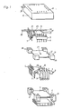
- Figure 1 illustrates the apparatus in accordance with the invention in perspective, with the individual parts spaced from each other
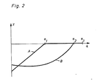
- Figure 2 is a diagram illustrating the positional alterations of the gripping means and contact springs as a function of the turning angle of the operating means.
- FIG 1 there are illustrated bell crank-shaped gripping means 1, which are pivotable about shafts 2 and are provided with gripping surfaces 3. Two of the gripping means are illustrated, there being four such in opposing pairs.
- the shafts rest in journalling recesses 4 on a base 5.
- the gripping means can grip a component 6, the gripping surfaces 3 resting against the side surfaces of the component between electrically conductive contact surfaces 8.
- Electrical conductors can be connected to the component at the contact surfaces with the aid of resilient contact pins 9. At their upper ends these are rigidly fastened in a casing 10, and extend out through it to constitute electrical connections.
- the contact pins extend through holes 7 bell crank shaped in actuators 11, so that they are flexibly guided and can be moved to a position of engagement with the contact surfaces 8.
- the actuators can glide against the inner bottom surface of the casing.
- a spacer means 12 is placed in the casing under the actuators and rests with its upper surfaces 14 against the inner bottom surface of the casing.
- the lower surfaces 15 of the spacer means rests against surfaces 16 on the base 5, thereby keeping the shafts 2 in their positions in the journalling recesses 4.
- the base has recesses 17 for locating the four corners of the component, which can thus be placed in a given position in the holder.
- the four gripping means can be turned about their shafts with the aid of a cam means 18 fixed to a shaft 20, with the aid of which it can be turned.
- the shaft 20 passes through a hole 27 in the spacer means 12.
- the shaft 20 carries another cam means formed as a disc 21 provided with four pins 22, running in slots 23 in the actuators.
- the disc 21 is provided with teeth 24 in mesh with a rack 25.
- the rack rests in recesses 26 made in the spacer means 12. Both end portions 28 and 29 of the rack project out through two holes in the casing.
- the slots have a position in relation to the shaft 20 such that the radial movement of the actuators will be very small during the first part of the turn of the shaft.
- the actuators are displaced towards the centre of shaft 20.
- the contact pins are thus moved into engagement against the contact surfaces 8 of the component.
- the apparatus will remain in this state due to friction, in spite of the spring bias in the contact pins, even if the exterior forces cease at the ends of the rack.
- the gripping means can be provided with returning means, e.g. a further cam means, which pivot the bell crank-shaped arms so that their gripping surfaces move away from the component when the rack 25 is reset.
- returning means e.g. a further cam means
- Figure 2 is a diagram illustrating the movement x of the gripping means and contact pins as a function of the turning angle a of the shaft.
- line A there is a linear change in the distance between the gripping surfaces of the gripping means and the component during the first part.
- the gripping means For the angle °1 the gripping means have come into engagement against the side surfaces of the component.
- the relative positions of the pins 22 and slots 23 are selected such that during this first part of the turning movement there is only a relatively small change in the radial movement of the contact pins, which is shown by the line B.
Landscapes
- Engineering & Computer Science (AREA)
- Microelectronics & Electronic Packaging (AREA)
- Physics & Mathematics (AREA)
- General Physics & Mathematics (AREA)
- Manipulator (AREA)
- Manufacturing Of Electrical Connectors (AREA)
- Testing Of Short-Circuits, Discontinuities, Leakage, Or Incorrect Line Connections (AREA)
- Tests Of Electronic Circuits (AREA)
- Connecting Device With Holders (AREA)
- Supply And Installment Of Electrical Components (AREA)
Claims (2)
Applications Claiming Priority (2)
| Application Number | Priority Date | Filing Date | Title |
|---|---|---|---|
| SE8207492 | 1982-12-29 | ||
| SE8207492A SE434899B (sv) | 1982-12-29 | 1982-12-29 | Hallare for att ansluta elektriska ledningar till kontaktytor pa elektroniska komponenter |
Publications (2)
| Publication Number | Publication Date |
|---|---|
| EP0116266A1 EP0116266A1 (de) | 1984-08-22 |
| EP0116266B1 true EP0116266B1 (de) | 1987-08-26 |
Family
ID=20349194
Family Applications (1)
| Application Number | Title | Priority Date | Filing Date |
|---|---|---|---|
| EP83850319A Expired EP0116266B1 (de) | 1982-12-29 | 1983-11-29 | Vorrichtung zur Verbindung elektrischer Leiter mit den Oberflächen elektrischer Komponenten |
Country Status (7)
| Country | Link |
|---|---|
| US (1) | US4556269A (de) |
| EP (1) | EP0116266B1 (de) |
| JP (1) | JPS59135375A (de) |
| CA (1) | CA1202392A (de) |
| DE (1) | DE3373243D1 (de) |
| NO (1) | NO160399C (de) |
| SE (1) | SE434899B (de) |
Families Citing this family (8)
| Publication number | Priority date | Publication date | Assignee | Title |
|---|---|---|---|---|
| US4671590A (en) * | 1985-03-06 | 1987-06-09 | Minnesota Mining And Manufacturing Company | Test clip for PLCC |
| US4981441A (en) * | 1985-03-06 | 1991-01-01 | Minnesota Mining And Manufacturing Co. | Test clip for PLCC |
| US4768972A (en) * | 1985-03-06 | 1988-09-06 | Minnesota Mining And Manufacturing Company | Test clip for PLCC |
| US4671592A (en) * | 1985-03-06 | 1987-06-09 | Minnesota Mining And Manufacturing Company | Test clip for PLCC |
| US5033977A (en) * | 1987-10-13 | 1991-07-23 | Minnesota Mining & Manufacturing Co. | Electrical connector and fixture for four-sided integrated circuit device |
| US4797118A (en) * | 1987-10-23 | 1989-01-10 | Itt Corporation | Test adapter for integrated circuit carrier |
| FR2664434B1 (fr) * | 1990-07-03 | 1992-10-09 | Alliance Tech Ind | Procede de manipulation d'un composant, notamment un connecteur, et outillage correspondant. |
| US5373230A (en) * | 1991-06-17 | 1994-12-13 | Itt Corporation | Test clip for five pitch IC |
Citations (4)
| Publication number | Priority date | Publication date | Assignee | Title |
|---|---|---|---|---|
| DE1934752A1 (de) * | 1969-07-09 | 1971-01-21 | Licentia Gmbh | Pruefadapter fuer elektrische Bausteine |
| GB1246101A (en) * | 1968-10-25 | 1971-09-15 | Electrosil Ltd | Integrated circuit testing |
| DE2046729A1 (de) * | 1970-09-22 | 1972-03-23 | Siemens Ag | Prüfklemme für lötfreie Verbindungen mit integrierten Bausteinen |
| GB2083298A (en) * | 1980-09-05 | 1982-03-17 | Augat Inc | Zero insertion force |
Family Cites Families (3)
| Publication number | Priority date | Publication date | Assignee | Title |
|---|---|---|---|---|
| BE789688A (fr) * | 1971-10-06 | 1973-04-04 | Amp Inc | Connecteur |
| US4012097A (en) * | 1975-10-17 | 1977-03-15 | Everett/Charles, Inc. | Combined test clip and component extraction tool |
| US4116518A (en) * | 1977-08-31 | 1978-09-26 | Ncr Corporation | Clip for paralleling packaged integrated circuit chips |
-
1982
- 1982-12-29 SE SE8207492A patent/SE434899B/sv not_active IP Right Cessation
-
1983
- 1983-11-29 EP EP83850319A patent/EP0116266B1/de not_active Expired
- 1983-11-29 DE DE8383850319T patent/DE3373243D1/de not_active Expired
- 1983-12-21 US US06/564,070 patent/US4556269A/en not_active Expired - Lifetime
- 1983-12-28 NO NO834851A patent/NO160399C/no not_active IP Right Cessation
- 1983-12-28 JP JP58245643A patent/JPS59135375A/ja active Granted
- 1983-12-28 CA CA000444323A patent/CA1202392A/en not_active Expired
Patent Citations (4)
| Publication number | Priority date | Publication date | Assignee | Title |
|---|---|---|---|---|
| GB1246101A (en) * | 1968-10-25 | 1971-09-15 | Electrosil Ltd | Integrated circuit testing |
| DE1934752A1 (de) * | 1969-07-09 | 1971-01-21 | Licentia Gmbh | Pruefadapter fuer elektrische Bausteine |
| DE2046729A1 (de) * | 1970-09-22 | 1972-03-23 | Siemens Ag | Prüfklemme für lötfreie Verbindungen mit integrierten Bausteinen |
| GB2083298A (en) * | 1980-09-05 | 1982-03-17 | Augat Inc | Zero insertion force |
Non-Patent Citations (1)
| Title |
|---|
| RCA, Technical notes, no. 1315, 12 October 1982 * |
Also Published As
| Publication number | Publication date |
|---|---|
| EP0116266A1 (de) | 1984-08-22 |
| CA1202392A (en) | 1986-03-25 |
| SE8207492L (sv) | 1984-06-30 |
| DE3373243D1 (en) | 1987-10-01 |
| NO160399B (no) | 1989-01-02 |
| SE434899B (sv) | 1984-08-20 |
| NO160399C (no) | 1989-04-12 |
| US4556269A (en) | 1985-12-03 |
| JPS59135375A (ja) | 1984-08-03 |
| SE8207492D0 (sv) | 1982-12-29 |
| JPH0350990B2 (de) | 1991-08-05 |
| NO834851L (no) | 1984-07-02 |
Similar Documents
| Publication | Publication Date | Title |
|---|---|---|
| EP0061615B1 (de) | Elektrische Prüfanordnung mit drehbaren Kontaktelementen | |
| EP0116266B1 (de) | Vorrichtung zur Verbindung elektrischer Leiter mit den Oberflächen elektrischer Komponenten | |
| US4498047A (en) | Integrated circuit mounting apparatus | |
| US4218817A (en) | Component mounting apparatus | |
| CA1237753A (en) | Simplified electric switch construction | |
| KR100344048B1 (ko) | Pga 패키지용의 점검 가능한 전기 커넥터 | |
| US4389627A (en) | Changeover switch for actuating a plurality of reed switches disposed in a circle | |
| US4415782A (en) | Sliding disc transducer actuator | |
| JP5117335B2 (ja) | 複合操作型入力装置 | |
| CN101730919A (zh) | 用于机动车的电开关 | |
| US20050179328A1 (en) | Motor-sensor system | |
| US4462435A (en) | Apparatus for securing a component to a printed circuit board | |
| US6312264B1 (en) | Connecting device | |
| US4179593A (en) | Change-over switch for printed circuit board | |
| US4579433A (en) | Film sensitivity setting device for camera | |
| US4569127A (en) | Apparatus for securing a component to a printed circuit board | |
| JP2000195636A (ja) | Icソケット | |
| EP1365428B1 (de) | Mehrachsiger Schalter mit redundanten Kontakten | |
| US3163730A (en) | Rotary electrical switches | |
| JPS59205116A (ja) | 回転スイツチ | |
| JP6395348B2 (ja) | 回転位置検出装置 | |
| GB2237146A (en) | A steering column switch | |
| JPH051865Y2 (de) | ||
| JP2769202B2 (ja) | 電気機器のスイッチ | |
| JPS5855618Y2 (ja) | 回転形可変抵抗器 |
Legal Events
| Date | Code | Title | Description |
|---|---|---|---|
| PUAI | Public reference made under article 153(3) epc to a published international application that has entered the european phase |
Free format text: ORIGINAL CODE: 0009012 |
|
| AK | Designated contracting states |
Designated state(s): CH DE FR GB IT LI NL |
|
| 17P | Request for examination filed |
Effective date: 19840615 |
|
| GRAA | (expected) grant |
Free format text: ORIGINAL CODE: 0009210 |
|
| AK | Designated contracting states |
Kind code of ref document: B1 Designated state(s): CH DE FR GB IT LI NL |
|
| ITF | It: translation for a ep patent filed |
Owner name: FUMERO BREVETTI S.N.C. |
|
| REF | Corresponds to: |
Ref document number: 3373243 Country of ref document: DE Date of ref document: 19871001 |
|
| ET | Fr: translation filed | ||
| PLBE | No opposition filed within time limit |
Free format text: ORIGINAL CODE: 0009261 |
|
| STAA | Information on the status of an ep patent application or granted ep patent |
Free format text: STATUS: NO OPPOSITION FILED WITHIN TIME LIMIT |
|
| 26N | No opposition filed | ||
| ITTA | It: last paid annual fee | ||
| PGFP | Annual fee paid to national office [announced via postgrant information from national office to epo] |
Ref country code: GB Payment date: 19991102 Year of fee payment: 17 Ref country code: FR Payment date: 19991102 Year of fee payment: 17 Ref country code: DE Payment date: 19991102 Year of fee payment: 17 Ref country code: CH Payment date: 19991102 Year of fee payment: 17 |
|
| PGFP | Annual fee paid to national office [announced via postgrant information from national office to epo] |
Ref country code: NL Payment date: 19991111 Year of fee payment: 17 |
|
| PG25 | Lapsed in a contracting state [announced via postgrant information from national office to epo] |
Ref country code: GB Free format text: LAPSE BECAUSE OF NON-PAYMENT OF DUE FEES Effective date: 20001129 |
|
| PG25 | Lapsed in a contracting state [announced via postgrant information from national office to epo] |
Ref country code: LI Free format text: LAPSE BECAUSE OF NON-PAYMENT OF DUE FEES Effective date: 20001130 Ref country code: CH Free format text: LAPSE BECAUSE OF NON-PAYMENT OF DUE FEES Effective date: 20001130 |
|
| PG25 | Lapsed in a contracting state [announced via postgrant information from national office to epo] |
Ref country code: NL Free format text: LAPSE BECAUSE OF NON-PAYMENT OF DUE FEES Effective date: 20010601 |
|
| REG | Reference to a national code |
Ref country code: CH Ref legal event code: PL |
|
| GBPC | Gb: european patent ceased through non-payment of renewal fee |
Effective date: 20001129 |
|
| PG25 | Lapsed in a contracting state [announced via postgrant information from national office to epo] |
Ref country code: FR Free format text: LAPSE BECAUSE OF NON-PAYMENT OF DUE FEES Effective date: 20010731 |
|
| NLV4 | Nl: lapsed or anulled due to non-payment of the annual fee |
Effective date: 20010601 |
|
| PG25 | Lapsed in a contracting state [announced via postgrant information from national office to epo] |
Ref country code: DE Free format text: LAPSE BECAUSE OF NON-PAYMENT OF DUE FEES Effective date: 20010801 |
|
| REG | Reference to a national code |
Ref country code: FR Ref legal event code: ST |