EP0114979A2 - Fördereinrichtung für Leiterplatten - Google Patents
Fördereinrichtung für Leiterplatten Download PDFInfo
- Publication number
- EP0114979A2 EP0114979A2 EP83112053A EP83112053A EP0114979A2 EP 0114979 A2 EP0114979 A2 EP 0114979A2 EP 83112053 A EP83112053 A EP 83112053A EP 83112053 A EP83112053 A EP 83112053A EP 0114979 A2 EP0114979 A2 EP 0114979A2
- Authority
- EP
- European Patent Office
- Prior art keywords
- transport
- transport element
- core
- printed circuit
- wire
- Prior art date
- Legal status (The legal status is an assumption and is not a legal conclusion. Google has not performed a legal analysis and makes no representation as to the accuracy of the status listed.)
- Granted
Links
Images
Classifications
-
- F—MECHANICAL ENGINEERING; LIGHTING; HEATING; WEAPONS; BLASTING
- F16—ENGINEERING ELEMENTS AND UNITS; GENERAL MEASURES FOR PRODUCING AND MAINTAINING EFFECTIVE FUNCTIONING OF MACHINES OR INSTALLATIONS; THERMAL INSULATION IN GENERAL
- F16C—SHAFTS; FLEXIBLE SHAFTS; ELEMENTS OR CRANKSHAFT MECHANISMS; ROTARY BODIES OTHER THAN GEARING ELEMENTS; BEARINGS
- F16C13/00—Rolls, drums, discs, or the like; Bearings or mountings therefor
-
- B—PERFORMING OPERATIONS; TRANSPORTING
- B65—CONVEYING; PACKING; STORING; HANDLING THIN OR FILAMENTARY MATERIAL
- B65G—TRANSPORT OR STORAGE DEVICES, e.g. CONVEYORS FOR LOADING OR TIPPING, SHOP CONVEYOR SYSTEMS OR PNEUMATIC TUBE CONVEYORS
- B65G39/00—Rollers, e.g. drive rollers, or arrangements thereof incorporated in roller-ways or other types of mechanical conveyors
- B65G39/02—Adaptations of individual rollers and supports therefor
Definitions
- the present invention relates to a transport element according to the preamble of claim 1 and to the use of this transport element.
- a conveyor in an automated production line for pre-tinned circuit boards with a horizontal passage of the circuit boards will be briefly described here.
- the printed circuit boards designed as printed circuits and intended to accommodate electrical components are often pre-tinned before the actual assembly with the components; i.e. a protective solderable coating is applied to the boards to thereby improve their soldering and storage properties.
- the circuit boards are first charged with a flux, then preheated and then connected to the liquid solder on one or both sides. In the horizontal position, the plates pass successively through a flux station, a preheating station, a tinning station and subsequent post-treatment stations.
- a conveying device for the horizontal transport of the printed circuit boards, a conveying device can be provided which leads through the individual stations and consists, for example, of driven transport rollers arranged in the conveying plane.
- the transport elements especially in the preheating station, have to meet a wide variety of requirements. Since the usual fluxes contain more or less aggressive acids or split off acids when heated, the transport elements must above all be acid-resistant. Furthermore, they must also be extremely heat-resistant. Today's transport elements, which are usually fitted with plastic parts, cannot meet these tough requirements and in particular tend to age relatively quickly.
- a further advantage of the invention is that the transport element can be manufactured very easily and without the use of special aids and therefore offers an inexpensive solution. Further advantages can be seen from the subsequent description of an exemplary embodiment.
- a transport element is described in more detail below with reference to a drawing.
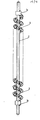
- the transport element consists of a rod-shaped core 2, at the two ends of which means (not shown in more detail) can be attached for insertion into a conveying device.
- a wire 3 is spirally applied, which in turn is helically shaped.
- one end is fixed on the core 2 on a holder 1a attached to it, and then the wire is continuously wound on the core 2 and the other end is fastened on another holder 1b.
- the wound wire 3 is only shown in detail in the drawing in the area of the ends of the core 2, in the middle area only the course of the envelope of the wire 3 is indicated.
- Collars can be used as holder 1.
- the desired diameter of the transport element can be determined in a simple manner by appropriate selection of the diameter of the compression spring strand.
- the necessary load-bearing capacity can also be achieved by a suitable choice of the wire diameter.
- the transport width is determined by the distance between the holders 1a, 1b.
- Transport elements designed in this way can advantageously be used, inter alia, in a conveyor device of a printed circuit board production line.
- several transport elements are arranged parallel to one another in the conveyor plane and at least some of them are driven in the same direction.
- the printed circuit boards are only in places according to the envelope of the transport elements this, resulting in a large number of irregularly distributed contact points on the continuous circuit board.
- the heat radiation acting on the printed circuit board in the preheating station is influenced only insignificantly by the transport elements, since the “radiation shadow” in this type of transport element is very small.
- the heat capacity of the transport elements is only low.
- the design of the transport elements according to the invention offers the advantage that when a printed circuit board which is not quite flat on its front side runs onto a transport element, it automatically returns to the conveying plane. All these advantages also apply without restriction to the case where the transport elements are arranged in pairs, ie one element above and one below the transport plane, and the printed circuit boards are pushed between the two transport elements of a pair.
- the special requirements in terms of heat and acid resistance in such a production line can be met by choosing materials with appropriate properties (e.g. stainless steel or spring steel).
- the number of support points of the printed circuit board on the transport elements can be influenced in that the wire 3 is wound onto the core 2 more or less closely.
Landscapes
- Engineering & Computer Science (AREA)
- Mechanical Engineering (AREA)
- General Engineering & Computer Science (AREA)
- Electric Connection Of Electric Components To Printed Circuits (AREA)
- Intermediate Stations On Conveyors (AREA)
- Structure Of Belt Conveyors (AREA)
- Chain Conveyers (AREA)
- Non-Reversible Transmitting Devices (AREA)
- Rollers For Roller Conveyors For Transfer (AREA)
Abstract
Description
- Die vorliegende Erfindung betrifft ein Transportelement gemäss dem Oberbegriff des Patentanspruches 1 sowie eine Verwendung dieses Transportelementes.
- In verschiedensten Gebieten des täglichen Lebens besteht die Aufgabe, Gegenstände mittels Förderanlagen von einem Ort zu einem anderen zu verschieben. Dies Ist auch in automatischen Fertigungsstrassen der Fall, wo das hergestellte Produkt während des Fertigungsablaufs verschiedene Stationen durchläuft und selbsttätig mittels einer Fördereinrichtung jeweils von einer Station zur nächsten transportiert wird. Dabei müssen die Fördereinrichtungen je nach Art ihres Einsatzes unterschiedlichsten Anforderungen genügen.
- Als Beispiel sei hier eine Fördereinrichtung in einer automatisierten Fertigungsstrasse für vorverzinnte Leiterplatten mit horizontalem Durchlauf der Leiterplatten kurz beschrieben. Die als gedruckte Schaltungen ausgelegten und zur Aufnahme von elektrischen Bauelementen vorgesehenen Leiterplatten werden oft vor der eigentlichen Bestückung mit den Bauelementen vorverzinnt; d.h. es wird eine schützende lötbare Beschichtung auf die Platten aufgebracht, um dadurch deren Löt- und Lagerhaltungseigenschaften zu verbessern. Hierzu werden die LeIterplatten zunächst mit einem Flussmittel beaufschlagt, hierauf vorgewärmt und anschliessend ein- oder beidseitig mit dem flüssigen Lot in Verbindung gebracht. Die Platten durchlaufen dabei in horizontaler Lage nacheinander eine Fluxstation, eine Vorwärmstation, eine Verzinnstation und nachfolgende Nachbehandiungsstationen. Für den horizontalen Transport der Leiterplatten kann eine durch die einzelnen Stationen hindurchführende Fördereinrichtung vorgesehen werden, die beispielsweise aus angetriebenen und in der Förderebene angeordneten Transportrollen besteht. Gerade in diesem Anwendungsfall müssen die Transportelemente insbesondere in der Vorwärmstation unterschiedlichsten Anforderungen gerecht werden. Da die üblichen Flussmittel mehr oder weniger aggressive Säuren enthalten oder beim Erhitzen Säuren abspalten, müssen die Transportelemente vor allem säurebeständig sein. Im weiteren müssen sie auch extrem wärmebeständig sein. Die heute üblicherweise mit Kunststoffteilen bestückten Transporteiemente vermögen diesen harten Anforderungen nicht zu genügen und neigen Insbesondere zu relativ rascher Alterung.
- Es Ist daher Aufgabe der vorliegenden Erfindung, ein Transportelement zu schaffen, das solchen Anforderungen genügt und sich Insbesondere auch für den Einsatz In Lelterplattenverzinnanlagen eignet. Die Lösung dieser Aufgabe gelingt mit einem Transportelement, wie es in den Ansprüchen gekennzeichnet ist.
- Neben der Erfüllung der erwähnten speziellen Anforderungen besteht ein weiterer Vorteil der Erfindung darin, dass das Transportelement sehr einfach und ohne Verwendung besonderer Hilfsmittel hergestellt werden kann und daher eine kostengünstige Lösung bietet. Weitere Vorteile sind aus der anschliessenden Beschreibung eines Ausführungsbeispieles ersichtlich.
- Nachstehend wird anhand einer Zeichnung ein Transportelement beispielsweise näher beschrieben.
- Das Transportelement besteht aus einem stabförmigen Kern 2, an dessen beiden Enden nicht weiter dargestellte Mittel zum Einsetzen in eine Fördereinrichtung angebracht werden können. Auf dem Kern 2 ist spiralförmig ein Draht 3 aufgebracht, der seinerseits schraubenlinienförmig geformt ist. Dazu eignet sich insbesondere ein bereits als Schraubenfeder vorgeformter Draht aus Federstahl, wie er für Druckfedem im Handel erhältlich ist. Dabei wird zunächst das eine Ende auf dem Kern 2 an einem auf diesem angebrachten Halter 1a fixiert und hierauf der Draht kontinuierlich auf dem Kern 2 aufgewickelt und das andere Ende an einem weiteren Halter 1b befestigt. In der Zeichnung ist der aufgewickelte Draht 3 der Einfachheit halber nur im Bereich der Enden des Kerns 2 im Einzelnen dargestellt, im mittleren Bereich ist lediglich der Verlauf der Hüllkurve des Drahtes 3 angedeutet. Als Halter 1 können Stellringe eingesetzt werden. Durch entsprechende Wahl des Durchmessers des Druckfederstranges lässt sich in einfacher Weise der gewünschte Durchmesser des Transportelementes festlegen. Ebenso kann die notwendige Tragkraft durch geeignete Wahl des Drahtdurchmessers erreicht werden. Die Transportbreite wird durch den Abstand der Halter 1a, 1b bestimmt.
- Derartig ausgebildete Transportelemente lassen sich u.a. in einer Fördereinrichtung einer Leiterplattenfertigungsstrasse vorteilhaft einsetzen. Hierzu werden mehrere Transportelemente parallel zueinander in der Förderebene angeordnet und wenigstens ein Teil davon in gleicher Richtung angetrieben. Dadurch liegen die beförderten Leiterplatten entsprechend der Hüllkurve der Transportelemente nur punktuell auf diesen auf, wodurch sich eine grosse Anzahl von unregelmässig verteilten Berührungspunkten auf der durchlaufenden Leiterplatte ergibt. Daraus resultiert Insbesondere Im Bereich der Vorwärmstation, wo die mit dem Flussmittel benetzten Leiterplatten eintreffen, der Vorteil, dass die Flussmittelschicht praktisch nicht beeinträchtigt wird. Ueberdies wird die in der Vorwärmstation beispielsweise von unten und/oder von oben auf die Leiterplatte einwirkende Wärmestrahlung durch die Transportelemente nur unwesentlich beeinflusst, da der "Strahlungsschatten" bei dieser Art von Transportelementen sehr klein ist. Die Wärmekapazität der Transportelemente Ist nur gering. Im weiteren bietet die erfindungsgemässe Ausgestaltung der Transportelemente den Vorteil, dass beim Auflaufen einer an ihrer Frontseite nicht ganz ebenen Leiterplatte auf ein Transportelement diese jeweils selbsttätig wieder in die Förderebene gelangt. Alle diese Vorteile gelten uneingeschränkt auch für den Fall, wo die Transportelemente paarweise, d.h. je ein Element über und unter der Transportebene, angeordnet sind und die Leiterplatten zwischen den beiden Transportelementen eines Paares hindurchgeschoben werden. Die in einer solchen Fertigungsstrasse besonderen Anforderungen bezüglich Wärme- und Säurebeständigkeit lassen sich durch Wahl von entsprechende Eigenschaften aufweisenden Materialien (z.B. rostfreier Stahl bzw. Federstahl) erfüllen. Die Zahl der Auflagepunkte der Leiterplatte auf den Transportelementen lässt sich dadurch beeinflussen, dass der Draht 3 mehr oder weniger eng auf den Kern 2 aufgewickelt wird.
- Die Anwendung des erfindungsgemässen Transportelementes ist keineswegs auf den beschriebenen Fall beschränkt. Dessen Einsatz in anderen Anwendungsbereichen ist durchaus denkbar.
Claims (4)
Priority Applications (1)
| Application Number | Priority Date | Filing Date | Title |
|---|---|---|---|
| AT83112053T ATE24698T1 (de) | 1983-01-27 | 1983-12-01 | Foerdereinrichtung fuer leiterplatten. |
Applications Claiming Priority (2)
| Application Number | Priority Date | Filing Date | Title |
|---|---|---|---|
| CH451/83 | 1983-01-27 | ||
| CH45183 | 1983-01-27 |
Publications (3)
| Publication Number | Publication Date |
|---|---|
| EP0114979A2 true EP0114979A2 (de) | 1984-08-08 |
| EP0114979A3 EP0114979A3 (en) | 1984-09-05 |
| EP0114979B1 EP0114979B1 (de) | 1987-01-07 |
Family
ID=4187326
Family Applications (1)
| Application Number | Title | Priority Date | Filing Date |
|---|---|---|---|
| EP83112053A Expired EP0114979B1 (de) | 1983-01-27 | 1983-12-01 | Fördereinrichtung für Leiterplatten |
Country Status (4)
| Country | Link |
|---|---|
| EP (1) | EP0114979B1 (de) |
| JP (1) | JPS59207310A (de) |
| AT (1) | ATE24698T1 (de) |
| DE (1) | DE3368905D1 (de) |
Cited By (1)
| Publication number | Priority date | Publication date | Assignee | Title |
|---|---|---|---|---|
| EP2435346A4 (de) * | 2009-05-26 | 2012-12-12 | Wuxi Suntech Power Co Ltd | Transportroller für den transport von artkeln |
Family Cites Families (3)
| Publication number | Priority date | Publication date | Assignee | Title |
|---|---|---|---|---|
| FR1012864A (fr) * | 1949-03-28 | 1952-07-18 | Dewandre Co Ltd C | Tube transmetteur de chaleur pourvu d'un enroulement en fil métallique |
| GB853449A (en) * | 1958-08-15 | 1960-11-09 | Reynolds Metals Co | Conveyor for sheet material |
| FR1348379A (fr) * | 1962-07-31 | 1964-01-10 | Rouleaux-supports élastiques, nettoyeurs et centreurs pour bandes transporteuses |
-
1983
- 1983-12-01 EP EP83112053A patent/EP0114979B1/de not_active Expired
- 1983-12-01 AT AT83112053T patent/ATE24698T1/de active
- 1983-12-01 DE DE8383112053T patent/DE3368905D1/de not_active Expired
-
1984
- 1984-01-24 JP JP59010909A patent/JPS59207310A/ja active Pending
Cited By (1)
| Publication number | Priority date | Publication date | Assignee | Title |
|---|---|---|---|---|
| EP2435346A4 (de) * | 2009-05-26 | 2012-12-12 | Wuxi Suntech Power Co Ltd | Transportroller für den transport von artkeln |
Also Published As
| Publication number | Publication date |
|---|---|
| EP0114979A3 (en) | 1984-09-05 |
| DE3368905D1 (en) | 1987-02-12 |
| EP0114979B1 (de) | 1987-01-07 |
| JPS59207310A (ja) | 1984-11-24 |
| ATE24698T1 (de) | 1987-01-15 |
Similar Documents
| Publication | Publication Date | Title |
|---|---|---|
| EP0236963B1 (de) | Verfahren zur Herstellung von Kontaktelementen | |
| EP0101782B1 (de) | Kleinformatige Kontaktstift-Baugruppe | |
| DE1948925C3 (de) | Verbindungsanordnung für Druckschaltungskarten | |
| DE69426344T2 (de) | Oberflächenmontierter elektrischer Verbinder | |
| DE2125609A1 (de) | Federkontakt sowie Verfahren zur Herstellung desselben.- | |
| EP0114979A2 (de) | Fördereinrichtung für Leiterplatten | |
| DE3022590C2 (de) | Verfahren zum Anbringen und Befestigen von parallel zueinander verlaufenden Stromzuführungsdrähten an gegenüber befindlichen Seitenflächen elektrischer Bauelemente | |
| CH627900A5 (de) | Element zum verbinden und abstuetzen zweier parallel angeordneter schaltungskarten. | |
| DE2948319B1 (de) | Verfahren zum Anbringen und Befestigen von Stromzufuehrungsdraehten an elektrischen Bauelementen | |
| DE3142629A1 (de) | Vorrichtung zum vorschieben in magazine aufgenommener einzelteile | |
| DE2146125C3 (de) | Tragkörper aus thermoplastischem Kunststoff für ein elektrisches Teil, insbesondere für eine Spule | |
| DE69111513T2 (de) | Halbleiterherstellungseinrichtung. | |
| DE69204784T2 (de) | Benutzungsverfahren eines Schlauchförderers. | |
| DE1465164B2 (de) | Elektrische Verbindungshülsen | |
| CH662011A5 (de) | Mobile stromversorgungsstation. | |
| DE2925847C2 (de) | Elektrischer Verbindungskontakt für koaxial ineinandersteckbare Leiterteile | |
| DE2927237C2 (de) | Verfahren sowie Vorrichtung zum Kontaktieren von elektrisch leitenden Blechen mit lackisoliertem Draht | |
| DE940954C (de) | Werkstuecktragschiene fuer Tauchvorrichtungen | |
| DE2332041C3 (de) | Induktor zur Magnetimpulsbearbeitung von metallischen Werkstücken | |
| AT392251B (de) | Vorrichtung zum ausrichten eines bleibend verformbaren verbindungsteiles | |
| DE1439035C (de) | Vorrichtung zur Durchfuhrung des Verfahrens zum Anbringen von Stromanschlus sen an scheibenförmige elektrische Bau elemente | |
| DE1216072B (de) | Loetstreifen mit einem bei der Arbeitstemperatur seines Lotes fest bleibenden Traeger | |
| DE917796C (de) | Spulenflansch fuer Gespraechszaehler | |
| DE1123378B (de) | Elektrische Verbindung | |
| DE2328969C3 (de) | Induktor zur Metalldruckverformung |
Legal Events
| Date | Code | Title | Description |
|---|---|---|---|
| PUAI | Public reference made under article 153(3) epc to a published international application that has entered the european phase |
Free format text: ORIGINAL CODE: 0009012 |
|
| PUAL | Search report despatched |
Free format text: ORIGINAL CODE: 0009013 |
|
| 17P | Request for examination filed |
Effective date: 19831212 |
|
| AK | Designated contracting states |
Designated state(s): AT BE CH DE FR GB IT LI NL SE |
|
| AK | Designated contracting states |
Designated state(s): AT BE CH DE FR GB IT LI NL SE |
|
| GRAA | (expected) grant |
Free format text: ORIGINAL CODE: 0009210 |
|
| AK | Designated contracting states |
Kind code of ref document: B1 Designated state(s): AT BE CH DE FR GB IT LI NL SE |
|
| PG25 | Lapsed in a contracting state [announced via postgrant information from national office to epo] |
Ref country code: NL Effective date: 19870107 Ref country code: IT Free format text: LAPSE BECAUSE OF FAILURE TO SUBMIT A TRANSLATION OF THE DESCRIPTION OR TO PAY THE FEE WITHIN THE PRESCRIBED TIME-LIMIT;WARNING: LAPSES OF ITALIAN PATENTS WITH EFFECTIVE DATE BEFORE 2007 MAY HAVE OCCURRED AT ANY TIME BEFORE 2007. THE CORRECT EFFECTIVE DATE MAY BE DIFFERENT FROM THE ONE RECORDED. Effective date: 19870107 |
|
| REF | Corresponds to: |
Ref document number: 24698 Country of ref document: AT Date of ref document: 19870115 Kind code of ref document: T |
|
| PG25 | Lapsed in a contracting state [announced via postgrant information from national office to epo] |
Ref country code: SE Effective date: 19870131 |
|
| REF | Corresponds to: |
Ref document number: 3368905 Country of ref document: DE Date of ref document: 19870212 |
|
| ET | Fr: translation filed | ||
| NLV1 | Nl: lapsed or annulled due to failure to fulfill the requirements of art. 29p and 29m of the patents act | ||
| PLBE | No opposition filed within time limit |
Free format text: ORIGINAL CODE: 0009261 |
|
| STAA | Information on the status of an ep patent application or granted ep patent |
Free format text: STATUS: NO OPPOSITION FILED WITHIN TIME LIMIT |
|
| 26N | No opposition filed | ||
| PG25 | Lapsed in a contracting state [announced via postgrant information from national office to epo] |
Ref country code: BE Effective date: 19871231 |
|
| BERE | Be: lapsed |
Owner name: SIEMENS A.G. BERLIN UND MUNCHEN Effective date: 19871231 |
|
| GBPC | Gb: european patent ceased through non-payment of renewal fee | ||
| PG25 | Lapsed in a contracting state [announced via postgrant information from national office to epo] |
Ref country code: GB Effective date: 19881122 |
|
| PG25 | Lapsed in a contracting state [announced via postgrant information from national office to epo] |
Ref country code: FR Free format text: LAPSE BECAUSE OF NON-PAYMENT OF DUE FEES Effective date: 19890831 |
|
| REG | Reference to a national code |
Ref country code: FR Ref legal event code: ST |
|
| PGFP | Annual fee paid to national office [announced via postgrant information from national office to epo] |
Ref country code: DE Payment date: 19901102 Year of fee payment: 8 |
|
| PGFP | Annual fee paid to national office [announced via postgrant information from national office to epo] |
Ref country code: AT Payment date: 19901105 Year of fee payment: 8 |
|
| PGFP | Annual fee paid to national office [announced via postgrant information from national office to epo] |
Ref country code: CH Payment date: 19910228 Year of fee payment: 8 |
|
| PG25 | Lapsed in a contracting state [announced via postgrant information from national office to epo] |
Ref country code: AT Effective date: 19911201 |
|
| PG25 | Lapsed in a contracting state [announced via postgrant information from national office to epo] |
Ref country code: LI Effective date: 19911231 Ref country code: CH Effective date: 19911231 |
|
| REG | Reference to a national code |
Ref country code: CH Ref legal event code: PL |
|
| PG25 | Lapsed in a contracting state [announced via postgrant information from national office to epo] |
Ref country code: DE Effective date: 19920901 |