EP0114218A2 - Window or door with a planking ledge made of wood or synthetic material - Google Patents
Window or door with a planking ledge made of wood or synthetic material Download PDFInfo
- Publication number
- EP0114218A2 EP0114218A2 EP83111203A EP83111203A EP0114218A2 EP 0114218 A2 EP0114218 A2 EP 0114218A2 EP 83111203 A EP83111203 A EP 83111203A EP 83111203 A EP83111203 A EP 83111203A EP 0114218 A2 EP0114218 A2 EP 0114218A2
- Authority
- EP
- European Patent Office
- Prior art keywords
- planking
- window
- row
- strip
- push
- Prior art date
- Legal status (The legal status is an assumption and is not a legal conclusion. Google has not performed a legal analysis and makes no representation as to the accuracy of the status listed.)
- Granted
Links
Images

Classifications
-
- E—FIXED CONSTRUCTIONS
- E06—DOORS, WINDOWS, SHUTTERS, OR ROLLER BLINDS IN GENERAL; LADDERS
- E06B—FIXED OR MOVABLE CLOSURES FOR OPENINGS IN BUILDINGS, VEHICLES, FENCES OR LIKE ENCLOSURES IN GENERAL, e.g. DOORS, WINDOWS, BLINDS, GATES
- E06B3/00—Window sashes, door leaves, or like elements for closing wall or like openings; Layout of fixed or moving closures, e.g. windows in wall or like openings; Features of rigidly-mounted outer frames relating to the mounting of wing frames
- E06B3/30—Coverings, e.g. protecting against weather, for decorative purposes
- E06B3/301—Coverings, e.g. protecting against weather, for decorative purposes consisting of prefabricated profiled members or glass
- E06B3/303—Covering metal or plastic frames with wooden profiled members
Definitions
- the invention relates to a window or a door with a frame and sash made of metal profiles, which are provided on the outside and / or on the inside with planking strips made of wood or plastic.
- Windows or doors of this type are known in which the blind and casement frames are made from steel tubes or from aluminum profiles and are provided with a wooden cladding. This wooden cladding is firmly connected to the metal frame. Due to temperature differences between the two materials and due to the change in the moisture content of the wood cladding, considerable stresses occur in these composite windows and doors, which lead to warping of the frame and sash. This results in leaks against driving rain and air as well as malfunctions in handling, especially since jamming in the rebate and / or in the lock area can occur.
- the invention has for its object.
- the attachment between the planking strips and the frame made of metal profiles to design menholmen so that the stresses occurring between the planking strips and the frame spars made of metal due to changing temperature loads and / or due to changing moisture contents of the planking strips cannot have a disadvantageous effect on the frame consisting of metal profiles.
- each planking strip has a receiving groove, which extends over its entire length and is open to the metal profile, for a holder row assigned to the metal profile and one of the planking strip, the holders of the one row to those of the other row in the Longitudinal direction of the metal profile or the planking strip are offset, each holder is provided with a push-through channel for an anchoring rod, the push-through channels of the two rows of holders are flush with one another or are slightly offset from one another and an anchoring rod pushed into the push-through channels of the holder extends over the entire length of the holder rows.
- the anchoring rod is made of a high-strength, elastic, rustproof material and can e.g. be made of stainless steel or a glass fiber reinforced plastic.
- the anchoring rod can also be designed as a plastic-coated steel rod.
- planking strip is made of real wood or plywood and swells or shrinks due to changing moisture levels, the resulting stresses are absorbed by the anchoring rod and compensated for by the elasticity of this anchoring rod.
- planking strips to the frame spars made of aluminum, for example, is very simple.
- planking strip is placed on the frame beam, so that the push-through channels of a individual holders are aligned with one another or are only slightly offset from one another.
- the anchoring rod is then pushed into the push-through channels of both rows of brackets.
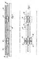
- the door shown in FIG. 1 has a frame 1 and a sash 2, which are equipped on the outside with cladding strips 3, 4, 5, 6, 7. From Fig. 1 it follows that the planking strips butt in the corner areas.
- the window frame spar 8 made of aluminum and the wing frame spar 9 also made of aluminum are equipped with planking strips 10 made of wood. These planking strips have a receiving groove 11 open to the metal profile for a row of brackets fixed to the metal profile and for a row of brackets.
- the individual holders 12 forming the rows mentioned match and are made in one piece from plastic.
- Each holder has a base plate 13 on which is arranged a sleeve-shaped body 15 which forms a push-through channel 14. 4 that the push-through channel 14 has its smallest cross-section in the central region and widens in cross-section towards the end openings 16. This widening of the cross section simplifies the insertion of an anchoring rod 17 into the push-through channels of the holder.
- the holders 12 assigned to the metal profile are screwed to the outer wall 18 of the metal profile.
- the base plate 13 is equipped with push-through openings 19.
- brackets 12 of the row of brackets fixed to the planking strip are offset in the longitudinal direction of the planking slab relative to the brackets of the row of brackets attached to the metal profile. Since when pushing the planking strip onto the outer wall of the metal profile, the push-through channels of the holders of both rows are aligned or only slightly offset from one another, the anchoring rod can be inserted into the push-through channels, which then fixes the planking strip relative to the metal profile.
- FIG 3 shows an offset of the central axes of two adjacent push-through channels by the amount X.
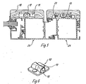
- the planking strip is equipped with a C-shaped anchoring groove 20 into which the base plate 13 of the holder 12 is inserted.
- the frame beam 21 made of a light metal profile has a C-shaped anchoring groove 22 into which the base plates 13 of the holders are inserted, which are fixed on the frame frame 21.
- the wing frame spar 23 in the exemplary embodiment according to FIG. 5 is equipped with a planking strip 10 which has a receiving groove 11 for the two rows of holders and for the anchoring rod 17. At the bottom of this receiving groove, the holders 12 of the row of holders of the planking strip 10 are screwed tight.
- the brackets of the row of brackets, which are attached to the casement spar, are also fixed by screws.
- the brackets in each row can be spaced about 30 cm apart.
- the anchoring rod 17 has a tip 24 at its insert.
Abstract
Description
Die Erfindung bezieht sich auf ein Fenster oder eine Tür mit einem aus Metallprofilen gefertigten Blend- und Flügelrahmen, die an der Außenseite und/oder an der Innenseite mit Beplankungsleisten aus Holz oder Kunststoff versehen sind.The invention relates to a window or a door with a frame and sash made of metal profiles, which are provided on the outside and / or on the inside with planking strips made of wood or plastic.
Es sind Fenster oder Türen dieser Art bekannt, bei denen die Blend-und Flügelrahmen aus Stahlrohren oder aus Aluminiumprofilen hergestellt und mit einer Holzverkleidung versehen sind.Diese Holzverkleidung ist fest mit dem Metallrahmen verbunden. Aufgrund von Temperaturdifferenzen zwischen den beiden Werkstoffen und aufgrund der Änderung des Feuchtigkeitsgehaltes der Holzverkleidung treten bei diesen Verbundfenstern und Verbundtüren erhebliche Spannungen auf, die zu einem Verzug des Blend- und des Flügelrahmens führen. Die Folge sind Undichtigkeiten gegen Schlagregen und Luft sowie Funktionsstörungen in der Handhabung, zumal ein Klemmen im Falz und/ oder im Schloßbereich auftreten kann.Windows or doors of this type are known in which the blind and casement frames are made from steel tubes or from aluminum profiles and are provided with a wooden cladding. This wooden cladding is firmly connected to the metal frame. Due to temperature differences between the two materials and due to the change in the moisture content of the wood cladding, considerable stresses occur in these composite windows and doors, which lead to warping of the frame and sash. This results in leaks against driving rain and air as well as malfunctions in handling, especially since jamming in the rebate and / or in the lock area can occur.
Der Erfindung liegt die Aufgabe zugrunde,.die Befestigung zwischen den Beplankungsleisten und den aus Metallprofilen bestehenden Rahmenholmen so zu gestalten, daß die zwischen den Beplankungsleisten und den Rahmenholmen aus Metall durch wechselnde Temperaturbelastungen und/oder durch wechselnde Feuchtigkeitsgehalte der Beplankungsleisten auftretenden Spannungen sich nicht nachteilig auf den aus Metallprofilen bestehenden Rahmen auswirken können.The invention has for its object. The attachment between the planking strips and the frame made of metal profiles to design menholmen so that the stresses occurring between the planking strips and the frame spars made of metal due to changing temperature loads and / or due to changing moisture contents of the planking strips cannot have a disadvantageous effect on the frame consisting of metal profiles.
Diese Aufgabe wird.nach der Erfindung dadurch gelöst, daß jede Beplankungsleiste eine über ihre gesamte Länge sich erstreckende, zu dem Metallprofil geöffnete Aufnahmenut für eine dem Metallprofil und eine der Beplankungsleiste zugeordnete Halterreihe aufweist, die Halter der einen Reihe zu denen der anderen Reihe in der Längsrichtung des Metallprofils bzw. der Beplankungsleiste versetzt sind, jeder Halter mit einem Durchsteckkanal für eine Verankerungsstange versehen ist, die Durchsteckkanäle beider Halterreihen miteinander fluchten oder geringfügig zueinander versetzt sind und sich über die gesamte Länge der Halterreihen eine in die Durchsteckkanäle der Halter eingeschobene Verankerungsstange erstreckt.This object is achieved according to the invention in that each planking strip has a receiving groove, which extends over its entire length and is open to the metal profile, for a holder row assigned to the metal profile and one of the planking strip, the holders of the one row to those of the other row in the Longitudinal direction of the metal profile or the planking strip are offset, each holder is provided with a push-through channel for an anchoring rod, the push-through channels of the two rows of holders are flush with one another or are slightly offset from one another and an anchoring rod pushed into the push-through channels of the holder extends over the entire length of the holder rows.
Die Verankerungsstange wird aus einem hochfesten, elastischen, nichtrostendem Material gefertigt und kann z.B. aus Edelstahl oder aus einem glasfaserverstärkten Kunststoff hergestellt sein. Die Verankerungsstange kann auch als kunststoffbeschichtete Stahlstange ausgebildet sein.The anchoring rod is made of a high-strength, elastic, rustproof material and can e.g. be made of stainless steel or a glass fiber reinforced plastic. The anchoring rod can also be designed as a plastic-coated steel rod.
Sofern die Beplankungsleiste aus einem Echtholz oder aus einem Schichtholz besteht und aufgrund sich ändernder Feuchtigkeitsgehalte quillt oder schrumpft, werden die sich daraus ergebenden Spannungen von der Verankerungsstange aufgenommen und aufgrund der Elastizität dieser Verankerungsstange ausgeglichen.If the planking strip is made of real wood or plywood and swells or shrinks due to changing moisture levels, the resulting stresses are absorbed by the anchoring rod and compensated for by the elasticity of this anchoring rod.
Die Montage und Befestigung der Beplankungsleisten an den z.B. aus Aluminium gefertigten Rahmenholmen ist sehr einfach. Nach der Festlegung einer Halterreihe an einem Rahmenholm und der Festlegung der zugeordneten Halterreihe an der Beplankungsleiste wird die Beplankungsleiste auf den Rahmenholm gelegt, so daß die Durchsteckkanäle der einzelnen Halter miteinander fluchten oder nur geringfügig zueinander versetzt sind. Hierauf wird die Verankerungsstange in die Durchsteckkanäle beider Halterreihen geschoben.The assembly and fastening of the planking strips to the frame spars made of aluminum, for example, is very simple. After the definition of a row of brackets on a frame rail and the determination of the associated row of brackets on the planking strip, the planking strip is placed on the frame beam, so that the push-through channels of a individual holders are aligned with one another or are only slightly offset from one another. The anchoring rod is then pushed into the push-through channels of both rows of brackets.
Ausführungsbeispiele der Erfindung sind in den Zeichnungen dargestellt und werden im folgenden beschrieben.Embodiments of the invention are shown in the drawings and are described below.
Es zeigen:
- Fig. 1 eine Tür im Aufriß, deren Flügelrahmen und deren Blendrahmen ,mit Beplankungsleisten versehen sind,
- Fig. 2 einen Horizontalschnitt durch einen Blendrahmen und einen Flügelrahmenholm einer Tür, die an der Außenseite mit Beplankungsleisten ausgerüstet sind,
- Fig. 3 einen Schnitt nach der Linie III-III in Fig. 2,
- Fig. 4 einen Schnitt nach der Linie IV-IV in Fig. 3,
- Fig. 5 eine Darstellung entsprechend der Fig. 2, jedoch mit anderen Befestigungsmitteln für die Halter und
- Fig. 6 einen Halter in perspektivischer Darstellung.
- 1 is a door in elevation, the casement and the window frame, are provided with planking strips,
- 2 shows a horizontal section through a frame and a casement frame of a door, which are equipped on the outside with cladding strips,
- 3 shows a section along the line III-III in FIG. 2,
- 4 shows a section along the line IV-IV in FIG. 3,
- Fig. 5 is a representation corresponding to FIG. 2, but with different fasteners for the holder and
- Fig. 6 is a holder in perspective.
Die in der Fig. 1 aufgezeigte Tür weist einen Blendrahmen 1 und einen Flügelrahmen 2 auf, die an der Außenseite mit Beplankungsleisten 3,4, 5,6,7 ausgerüstet sind. Aus der Fig. 1 ergibt-sich, daß die Beplankungsleisten in den Eckbereichen stumpf zusammenstoßen.The door shown in FIG. 1 has a frame 1 and a
Bei dem Ausführungsbeispiel nach der Fig. 2 sind der aus Aluminium gefertigte Blendrahmenholm 8 und der ebenfalls aus Aluminium hergestellte Flügelrahmenholm 9 mit aus Holz bestehenden Beplankungsleisten 10 ausgerüstet. Diese Beplankungsleisten weisen eine zu dem Metallprofil geöffnete Aufnahmenut 11 für eine an dem Metallprofil und für eine an der Beplankungsleiste festgelegte Halterreihe auf.In the exemplary embodiment according to FIG. 2, the window frame spar 8 made of aluminum and the wing frame spar 9 also made of aluminum are equipped with
In den dargestellten_Ausführungsbeispielen stimmen die einzelnen die genannten Reihen bildenden Halter 12 überein und sind einstükkig aus Kunststoff gefertigt. Jeder Halter weist eine Grundplatte 13 auf, auf der ein hülsenförmiger, einen Durchsteckkanal 14 bildender Körper 15 angeordnet ist. Aus der Fig. 4 ergibt sich, daß der Durchsteckkanal 14 im mittleren Bereich seinen kleinsten Querschnitt aufweist und sich zu den stirnseitigen Öffnungen 16 hin sich im Querschnitt erweitert. Durch diese Querschnittserweiterung wird das Einführen einer Verankerungsstange 17 in die Durchsteckkanäle der Halter vereinfacht.In the illustrated exemplary embodiments, the
Bei dem Ausführungsbeispiel nach der Fig. 2 sind die dem Metallprofil zugeordneten Halter 12 mit der Außenwand 18 des Metallprofils verschraubt. Zu diesem Zweck ist die Grundplatte 13 mit Durchstecköffnungen 19 ausgerüstet.In the embodiment according to FIG. 2, the
Die Halter 12 der an der Beplankungsleiste festgelegten Halterreihe sind gegenüber den Haltern der am Metallprofil befestigten Halterreihe in der Längsrichtung der Beplankungsleiste versetzt. Da beim Auflegen der Beplankungsleiste auf die Außenwand des Metallprofils die Durchsteckkanäle der Halter beider Reihen miteinander fluchten oder nur geringfügig zueinander versetzt sind, kann in die Durchsteckkanäle die Verankerungsstange eingeschoben werden, die dann die Beplankungsleiste gegenüber dem Metallprofil festlegt.The
In der Fig. 3 ist eine Versetzung der Mittelachsen zweier benachbarter Durchsteckkanäle um den Betrag X aufgezeigt. Durch eine derartige Versetzung wird der Verankerungsstange eine Spannung aufgegeben, die bewirkt, daß die Beplankungsleiste fest an die Außenfläche des Metallprofils gezogen wird.3 shows an offset of the central axes of two adjacent push-through channels by the amount X. With such a displacement, a tension is applied to the anchoring rod, which causes the planking strip to be pulled firmly onto the outer surface of the metal profile.
Zur Festlegung der Halter 12 an der Beplankungsleiste 10 ist die Beplankungsleiste mit einer C-förmigen Verankerungsnut 20 ausgerüstet, in die die Grundplatte 13 der Halter 12 eingeschoben wird.To fix the
Bei dem Ausführungsbeispiel nach der Fig. 5 weist der aus einem Leichtmetallprofil gefertigte Blendrahmenholm 21 eine C-förmige Verankerungsnut 22 auf, in die die Grundplatten 13 der Halter eingeschoben werden, die am Blendrahmenholm 21 festgelegt werden.In the embodiment according to FIG. 5, the
Der Flügelrahmenholm 23 bei dem Ausführungsbeispiel nach der Fig. 5 ist mit einer Beplankungsleiste 10 ausgerüstet, die eine Aufnahmenut 11 für die beiden Halterreihen und für die Verankerungsstange 17 aufweist. Am Boden dieser Aufnahmenut sind die Halter 12 der Halterreihe der Beplankungsleiste 10 festgeschraubt. Auch die Halter der Halterreihe, die an dem Flügelrahmenholm befestigt ist, sind durch Schrauben festgelegt.The wing frame spar 23 in the exemplary embodiment according to FIG. 5 is equipped with a
Die Halter in jeder Reihe können in einem Abstand von ca. 30 cm angeordnet sein.The brackets in each row can be spaced about 30 cm apart.
Zur Vereinfachung des Einführens der Verankerungsstange 17 in die Durchsteckkanäle 14 weist die Verankerungsstange 17 an ihrem Einführende eine Spitze 24 auf.To simplify the insertion of the
- 1 Blendrahmen1 frame
- 2 Flügelrahmen2 casement frames
- 3 Beplankungsleiste3 planking strip
- 4 Beplankungsleiste4 planking strip
- 5 Beplankungsleiste5 planking strip
- 6 Beplankungsleiste6 planking strip
- 7 Beplankungsleiste7 planking strip
- 8 Blendrahmenholm8 frame spar
- 9 Flügelrahmenholm9 casement strut
- 10 Beplankungsleiste10 planking strip
- 11 Aufnahmenut11 receiving groove
- 12 Halter12 holders
- 13 Grundplatte13 base plate
- 14 Durchsteckkanal14 push-through channel
- 15 Körper15 bodies
- 16 öffnung16 opening
- 17 Verankerungsstange17 anchoring rod
- 18 Außenwand18 outer wall
- 19 Durchstecköffnung19 push-through opening
- 20 Verankerungsnut20 anchoring groove
- 21 Blendrahmenholm21 frame spar
- 22 Verankerungsnut22 anchoring groove
- 23 Flügelrahmenholm23 casement strut
Claims (7)
Priority Applications (1)
| Application Number | Priority Date | Filing Date | Title |
|---|---|---|---|
| AT83111203T ATE26322T1 (en) | 1983-01-21 | 1983-11-10 | WINDOW OR DOOR WITH WOODEN OR PLASTIC PANELING. |
Applications Claiming Priority (2)
| Application Number | Priority Date | Filing Date | Title |
|---|---|---|---|
| DE19833301940 DE3301940A1 (en) | 1983-01-21 | 1983-01-21 | WINDOWS OR DOORS WITH WOOD OR PLASTIC PANELS |
| DE3301940 | 1983-01-21 |
Publications (3)
| Publication Number | Publication Date |
|---|---|
| EP0114218A2 true EP0114218A2 (en) | 1984-08-01 |
| EP0114218A3 EP0114218A3 (en) | 1985-01-09 |
| EP0114218B1 EP0114218B1 (en) | 1987-04-01 |
Family
ID=6188848
Family Applications (1)
| Application Number | Title | Priority Date | Filing Date |
|---|---|---|---|
| EP83111203A Expired EP0114218B1 (en) | 1983-01-21 | 1983-11-10 | Window or door with a planking ledge made of wood or synthetic material |
Country Status (5)
| Country | Link |
|---|---|
| EP (1) | EP0114218B1 (en) |
| AT (1) | ATE26322T1 (en) |
| DE (2) | DE3301940A1 (en) |
| DK (1) | DK156086C (en) |
| NO (1) | NO160094C (en) |
Cited By (6)
| Publication number | Priority date | Publication date | Assignee | Title |
|---|---|---|---|---|
| GB2216580A (en) * | 1988-01-07 | 1989-10-11 | Edward Wilkinson | A composite section frame element |
| GB2220218A (en) * | 1988-06-30 | 1990-01-04 | Decane Limited | Window units |
| GB2249575A (en) * | 1990-10-31 | 1992-05-13 | Reddish Joinery Ltd | Window frame cladding |
| GB2251645A (en) * | 1990-12-18 | 1992-07-15 | Arcon Aluminium Ltd | Wood clad metal frame members |
| WO1998019026A1 (en) * | 1996-10-31 | 1998-05-07 | Jouko Passi | Wood piece and method for supporting it |
| US7533507B2 (en) | 2002-10-22 | 2009-05-19 | Sashlite, Llc | Clip and sash assembly for mounting components between glazing panes |
Families Citing this family (2)
| Publication number | Priority date | Publication date | Assignee | Title |
|---|---|---|---|---|
| DE4009384A1 (en) * | 1990-03-23 | 1991-09-26 | Elram Wintergartentechnik Gmbh | Window frame section with metal core - has top wooden cladding piece attached by ridges to wooden filler piece |
| DE4326115A1 (en) * | 1993-08-04 | 1995-02-09 | Hubert Funk | Profile seal for windows, and process and apparatus for fitting it |
Citations (2)
| Publication number | Priority date | Publication date | Assignee | Title |
|---|---|---|---|---|
| CH435652A (en) * | 1965-11-04 | 1967-05-15 | Aluvo Aluminium Bauelemente Vo | Device for fastening the metal profile frames in wood-light metal windows and doors |
| DE8033474U1 (en) * | 1980-12-17 | 1981-05-27 | Lilge, Helmut, 8360 Deggendorf | BUILDING FRAME, ESPECIALLY DOOR OR WINDOW FLOOR |
Family Cites Families (1)
| Publication number | Priority date | Publication date | Assignee | Title |
|---|---|---|---|---|
| DE1683242A1 (en) * | 1966-06-15 | 1971-02-11 | Mathes Kg Heinz | Window, door or the like with single or double insulating glazing |
-
1983
- 1983-01-21 DE DE19833301940 patent/DE3301940A1/en active Granted
- 1983-11-10 AT AT83111203T patent/ATE26322T1/en not_active IP Right Cessation
- 1983-11-10 EP EP83111203A patent/EP0114218B1/en not_active Expired
- 1983-11-10 DE DE8383111203T patent/DE3370673D1/en not_active Expired
-
1984
- 1984-01-20 NO NO840220A patent/NO160094C/en unknown
- 1984-01-20 DK DK024584A patent/DK156086C/en active
Patent Citations (2)
| Publication number | Priority date | Publication date | Assignee | Title |
|---|---|---|---|---|
| CH435652A (en) * | 1965-11-04 | 1967-05-15 | Aluvo Aluminium Bauelemente Vo | Device for fastening the metal profile frames in wood-light metal windows and doors |
| DE8033474U1 (en) * | 1980-12-17 | 1981-05-27 | Lilge, Helmut, 8360 Deggendorf | BUILDING FRAME, ESPECIALLY DOOR OR WINDOW FLOOR |
Cited By (8)
| Publication number | Priority date | Publication date | Assignee | Title |
|---|---|---|---|---|
| GB2216580A (en) * | 1988-01-07 | 1989-10-11 | Edward Wilkinson | A composite section frame element |
| GB2216580B (en) * | 1988-01-07 | 1992-08-19 | Edward Wilkinson | A composite section frame element |
| GB2220218A (en) * | 1988-06-30 | 1990-01-04 | Decane Limited | Window units |
| GB2249575A (en) * | 1990-10-31 | 1992-05-13 | Reddish Joinery Ltd | Window frame cladding |
| GB2251645A (en) * | 1990-12-18 | 1992-07-15 | Arcon Aluminium Ltd | Wood clad metal frame members |
| WO1998019026A1 (en) * | 1996-10-31 | 1998-05-07 | Jouko Passi | Wood piece and method for supporting it |
| US7533507B2 (en) | 2002-10-22 | 2009-05-19 | Sashlite, Llc | Clip and sash assembly for mounting components between glazing panes |
| US7856782B2 (en) | 2002-10-22 | 2010-12-28 | Sashlite, Llc | Grid muntin retaining clips for muntins |
Also Published As
| Publication number | Publication date |
|---|---|
| EP0114218B1 (en) | 1987-04-01 |
| NO840220L (en) | 1984-07-23 |
| NO160094B (en) | 1988-11-28 |
| DE3370673D1 (en) | 1987-05-07 |
| DK156086B (en) | 1989-06-19 |
| DK24584A (en) | 1984-07-22 |
| NO160094C (en) | 1989-03-08 |
| EP0114218A3 (en) | 1985-01-09 |
| DK156086C (en) | 1989-11-06 |
| DE3301940A1 (en) | 1984-07-26 |
| DK24584D0 (en) | 1984-01-20 |
| DE3301940C2 (en) | 1991-10-10 |
| ATE26322T1 (en) | 1987-04-15 |
Similar Documents
| Publication | Publication Date | Title |
|---|---|---|
| DE3011946C2 (en) | Sliding window or door | |
| EP0056484A2 (en) | Wing of a door or a window equipped with a fitting for sliding bars | |
| EP0549769A1 (en) | Fire-resistant glass partition. | |
| DE3301940C2 (en) | ||
| DE2023536A1 (en) | Metal frame with insulating effect for holding panels | |
| DE2502101A1 (en) | PIPE FRAME CONSTRUCTION FOR DOORS AND FIXED GLAZING, IN PARTICULAR IN SMOKE PROTECTIVE DESIGN | |
| DE884097C (en) | Roll closure for doors, windows, etc. like | |
| EP1275810B1 (en) | Kit for installing a wall element to an opening of a double shell stud wall | |
| DE2732595A1 (en) | Non-distorting framed exterior door - has continuous metal reinforcing bar on lock case side of frame and uses profiles which may be form locked to strips | |
| DE2724377A1 (en) | Window, door or wall composite profile bar assembly - has elastically deformed rubber inlay between connector flanges and bar chamber sides | |
| DE2750351A1 (en) | Pressed profile with anchoring slots - has symmetrically arranged slots bounded by T=section longitudinal ribs | |
| DE3202833A1 (en) | Facing for a frame fastened in a building and intended for a room door or house door or the like | |
| DE2642746C3 (en) | Frames for windows made of foam with embedded hollow metal profiles | |
| EP0646212B1 (en) | Fire barrier for buildings, especially a fire door or window | |
| DE1952195U (en) | FOR IMMEDIATE USE IN THE WINDOW AND DOOR OPENINGS OF A BODY CONSTRUCTION OF A SPECIFIC WINDOW OR. PRE-FABRICATED DOOR COMPONENT. | |
| DE7234355U (en) | Roll bar | |
| DE2553801A1 (en) | Section assembled door or window frame - comprises homologous adjacent frame parts with clamp units engaging counter pieces | |
| DE4325698A1 (en) | Side door | |
| DE2225653A1 (en) | WINDOW FRAME | |
| CH656180A5 (en) | BULLETPROOF FRAME COMPOSED OF PROFILES. | |
| DE102022120797A1 (en) | Insulating web for connecting two profile elements to produce a thermally insulated profile and such a profile | |
| DE3200261A1 (en) | Securing means for windows and doors of an assembly building consisting of prefabricated parts | |
| DE3447402A1 (en) | Garage door, fence or the like | |
| DE2062090A1 (en) | Holder for discs or the like. Fillings on door and / or window frames, in particular partition walls | |
| DE7717167U1 (en) | DOOR WINGS |
Legal Events
| Date | Code | Title | Description |
|---|---|---|---|
| PUAI | Public reference made under article 153(3) epc to a published international application that has entered the european phase |
Free format text: ORIGINAL CODE: 0009012 |
|
| AK | Designated contracting states |
Designated state(s): AT CH DE FR LI SE |
|
| PUAL | Search report despatched |
Free format text: ORIGINAL CODE: 0009013 |
|
| 17P | Request for examination filed |
Effective date: 19840828 |
|
| AK | Designated contracting states |
Designated state(s): AT CH DE FR LI SE |
|
| 17Q | First examination report despatched |
Effective date: 19860224 |
|
| GRAA | (expected) grant |
Free format text: ORIGINAL CODE: 0009210 |
|
| AK | Designated contracting states |
Kind code of ref document: B1 Designated state(s): AT CH DE FR LI SE |
|
| REF | Corresponds to: |
Ref document number: 26322 Country of ref document: AT Date of ref document: 19870415 Kind code of ref document: T |
|
| ET | Fr: translation filed | ||
| REF | Corresponds to: |
Ref document number: 3370673 Country of ref document: DE Date of ref document: 19870507 |
|
| PLBE | No opposition filed within time limit |
Free format text: ORIGINAL CODE: 0009261 |
|
| STAA | Information on the status of an ep patent application or granted ep patent |
Free format text: STATUS: NO OPPOSITION FILED WITHIN TIME LIMIT |
|
| 26N | No opposition filed | ||
| EAL | Se: european patent in force in sweden |
Ref document number: 83111203.2 |
|
| PGFP | Annual fee paid to national office [announced via postgrant information from national office to epo] |
Ref country code: FR Payment date: 19950926 Year of fee payment: 13 |
|
| PGFP | Annual fee paid to national office [announced via postgrant information from national office to epo] |
Ref country code: SE Payment date: 19951005 Year of fee payment: 13 |
|
| PGFP | Annual fee paid to national office [announced via postgrant information from national office to epo] |
Ref country code: AT Payment date: 19951129 Year of fee payment: 13 |
|
| PGFP | Annual fee paid to national office [announced via postgrant information from national office to epo] |
Ref country code: CH Payment date: 19951130 Year of fee payment: 13 |
|
| PG25 | Lapsed in a contracting state [announced via postgrant information from national office to epo] |
Ref country code: AT Effective date: 19961110 |
|
| PG25 | Lapsed in a contracting state [announced via postgrant information from national office to epo] |
Ref country code: SE Effective date: 19961111 |
|
| PGFP | Annual fee paid to national office [announced via postgrant information from national office to epo] |
Ref country code: DE Payment date: 19961114 Year of fee payment: 14 |
|
| PG25 | Lapsed in a contracting state [announced via postgrant information from national office to epo] |
Ref country code: LI Effective date: 19961130 Ref country code: CH Effective date: 19961130 |
|
| REG | Reference to a national code |
Ref country code: CH Ref legal event code: PL |
|
| PG25 | Lapsed in a contracting state [announced via postgrant information from national office to epo] |
Ref country code: FR Effective date: 19970731 |
|
| EUG | Se: european patent has lapsed |
Ref document number: 83111203.2 |
|
| REG | Reference to a national code |
Ref country code: FR Ref legal event code: ST |
|
| PG25 | Lapsed in a contracting state [announced via postgrant information from national office to epo] |
Ref country code: DE Free format text: LAPSE BECAUSE OF NON-PAYMENT OF DUE FEES Effective date: 19980801 |