EP0056484A2 - Wing of a door or a window equipped with a fitting for sliding bars - Google Patents
Wing of a door or a window equipped with a fitting for sliding bars Download PDFInfo
- Publication number
- EP0056484A2 EP0056484A2 EP81110716A EP81110716A EP0056484A2 EP 0056484 A2 EP0056484 A2 EP 0056484A2 EP 81110716 A EP81110716 A EP 81110716A EP 81110716 A EP81110716 A EP 81110716A EP 0056484 A2 EP0056484 A2 EP 0056484A2
- Authority
- EP
- European Patent Office
- Prior art keywords
- faceplate
- receiving groove
- fitting
- door
- window sash
- Prior art date
- Legal status (The legal status is an assumption and is not a legal conclusion. Google has not performed a legal analysis and makes no representation as to the accuracy of the status listed.)
- Granted
Links
- 210000002105 tongue Anatomy 0.000 claims abstract description 12
- 238000004873 anchoring Methods 0.000 claims abstract description 9
- 239000000463 material Substances 0.000 claims abstract description 5
- 125000006850 spacer group Chemical group 0.000 claims description 7
- 238000004519 manufacturing process Methods 0.000 claims description 3
- 229910001220 stainless steel Inorganic materials 0.000 claims description 3
- 239000010935 stainless steel Substances 0.000 claims description 3
- 238000005452 bending Methods 0.000 description 2
- 230000005540 biological transmission Effects 0.000 description 1
- 238000010276 construction Methods 0.000 description 1
- 239000002023 wood Substances 0.000 description 1
Images


Classifications
-
- E—FIXED CONSTRUCTIONS
- E05—LOCKS; KEYS; WINDOW OR DOOR FITTINGS; SAFES
- E05C—BOLTS OR FASTENING DEVICES FOR WINGS, SPECIALLY FOR DOORS OR WINDOWS
- E05C9/00—Arrangements of simultaneously actuated bolts or other securing devices at well-separated positions on the same wing
- E05C9/004—Faceplates ; Fixing the faceplates to the wing
Definitions
- the invention relates to a door or window wing equipped with a faceplate fitting, which fitting has a faceplate covering a receiving groove of the wing for a locking bar, and a locking bar which is displaceable in its longitudinal axis and is equipped with locking means is mounted.
- Cuff rail fittings are known, in which locking bars equipped with locking rollers are slidably mounted on cuff rails fixed to the casement frame by means of rivets or other fastening means.
- faceplate rail fittings which have to be coordinated with the dimensions of the window or door leaf in terms of their length, are inserted into the grooves in the leaf frame and the respective faceplate rail is fastened to the leaf frame using screws that are screwed into the groove base.
- the invention has for its object to design a door or window wing of the type mentioned in such a way that, in addition to simple assembly, increased functional reliability of the faceplate fittings is ensured in that higher loads can be absorbed by the fastening means for the faceplate rails.
- the faceplate is fastened to U-shaped holders, the side legs of which have resilient, undercutting webs of the receiving groove engaging tongues and the free longitudinal edges of the holders are provided with anchoring projections engaging in the bottom of the receiving groove .
- the faceplate is fastened by means of at least one screw to the wall of the U-shaped holder which extends parallel to the faceplate and lies on the webs of the receiving groove which form undercuts.
- the width of the U-shaped holder corresponds to that clear width between the mentioned webs.
- a spacer is arranged in an elongated hole in the locking bar, the fastening screw extending through the bore of the spacer.
- the screws that fix the faceplate to the U-shaped brackets are short in length and therefore have to absorb a small amount of bending stress. These screws are also anchored in the holders made of high-strength material and are not screwed into a relatively soft frame material.
- the fastening means according to the invention for the faceplate result in a four- to five-fold increase in the force transfer in all types of windows compared to the known constructions. This abrupt increase in power transmission is achieved with structurally simple means.
- the sash profile 1 is equipped with a receiving groove 2 for a faceplate fitting 3.
- the receiving groove 2 has an outer part 4 and one internal part 5. Between these parts webs 6 are provided which have undercut surfaces 7.
- a faceplate 8 is arranged, which is fastened to U-shaped holders 9 by means of screws 10.
- the U-shaped holders 9 have a wall 11 which runs parallel to the faceplate 8 and which is provided with one or more threaded bores for screwing in the screws 10. From the longitudinal edges of the wall 11 extend at a right angle side legs 12 which have resilient tongues 13 projecting outwards which engage the webs 6 with their free edges.
- the outside distance of the side legs 12 corresponds to the clear width between the webs 6, so that the U-shaped holder can be inserted into the inner part 5 of the receiving groove 2 without difficulty.
- the free longitudinal edges 14 of the side legs 12 are equipped with anchoring projections 16 which engage in the bottom 15 of the receiving groove 2.
- anchoring projections 16 can be designed as wedge-shaped cutting edges.
- the anchoring projections 16 are arranged in the end regions and in the central region of each side leg 12.
- the U-shaped holder 9 are preferably made of stainless steel.
- each side leg 12 of the holder is equipped with two rows of tongues 17, 18, each row being composed of three tongues of different lengths and the tongues being arranged in a stepped manner so that with Manufacturing tolerances or manufacturing inaccuracies that could impair the correct fixing of the U-shaped holder in the receiving groove can be bridged over their free edges.
- a locking bar 19 is provided which is displaceable in its longitudinal axis and is arranged between the U-shaped holders 9 and the faceplate 8 and has an elongated hole 20 in which a spacer bushing 21 is provided whose bore the screw 10 is guided.
- the spacer bushing 21 maintains the distance between the faceplate 8 and the holders 9 which is required for the mobility of the locking bar 19.
Landscapes
- Engineering & Computer Science (AREA)
- Mechanical Engineering (AREA)
- Door And Window Frames Mounted To Openings (AREA)
- Specific Sealing Or Ventilating Devices For Doors And Windows (AREA)
- Securing Of Glass Panes Or The Like (AREA)
- Support Devices For Sliding Doors (AREA)
Abstract
Der mit einem Stulpschienenbeschlag ausgerüstete Flügelrahmen 1 einer Tür oder eines Fensters weist eine mit einer Stulpschiene 8 abgedeckte Aufnahmenut für eine Riegelstange 19 auf, die in ihrer Längsachse verschiebbar zwischen der Stulpschiene und mehreren U-förmigen Haltern 9 aus einem hochfesten Material gelagert ist. Die Seitenschenkel 12 der Halter 9 sind mit Zungen 13 versehen, die Stege 6 der Aufnahmenut hintergreifen. Ferner weisen die freien Längsränder der Seitenschenkel Verankerungsvorsprünge 16 auf, die in den Boden 15 der Aufnahmenut eingreifen.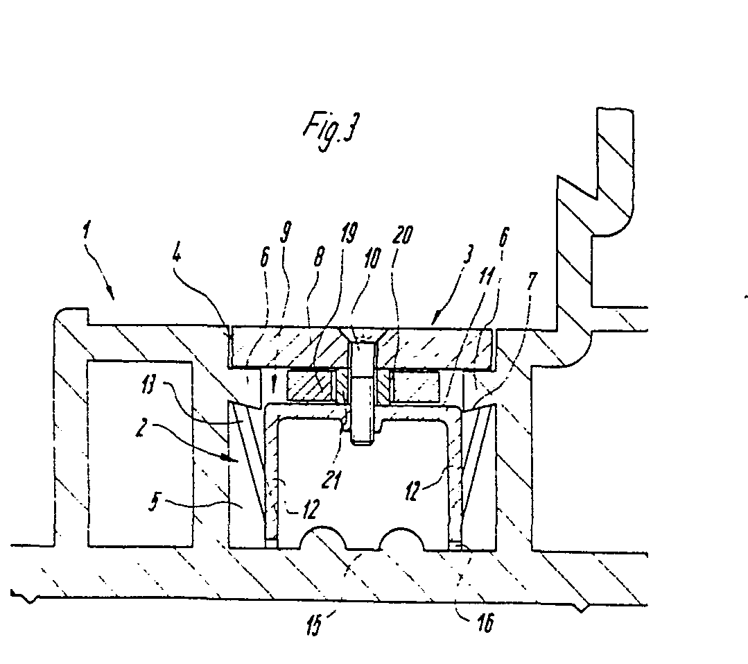
Description
Die Erfindung bezieht sich auf einen mit einem Stulpschienenbeschlag ausgerüsteten Tür- oder Fensterflügel, welcher Beschlag eine eine Aufnahmenut des Flügels für eine-Riegelstange abdeckende Stulpschiene aufweist, anjder eine, in ihrer Längsachse verschiebbare, mit Verriegelungsmitteln ausgerüstete Riegelstange gelagert ist.The invention relates to a door or window wing equipped with a faceplate fitting, which fitting has a faceplate covering a receiving groove of the wing for a locking bar, and a locking bar which is displaceable in its longitudinal axis and is equipped with locking means is mounted.
Es sind Stulpschienenbeschläge bekannt, bei denen an am Flügelrahmen festgelegten Stulpschienen mittels Nieten oder anderer Befestigungsmittel mit Schließrollen ausgerüstete Riegelstangen schiebbar gelagert sind. Diese Stulpschienenbeschläge, die in Hinsicht auf ihre Länge mit den Abmaßen des Fenster- oder Türflügels abgestimmt werden müssen, werden in Aufnahmenuten am Flügelrahmen eingelegt und es wird die jeweilige Stulpschiene mittels Schrauben, die in den Nutboden eingeschraubt werden, am Flügelrahmen befestigt.Cuff rail fittings are known, in which locking bars equipped with locking rollers are slidably mounted on cuff rails fixed to the casement frame by means of rivets or other fastening means. These faceplate rail fittings, which have to be coordinated with the dimensions of the window or door leaf in terms of their length, are inserted into the grooves in the leaf frame and the respective faceplate rail is fastened to the leaf frame using screws that are screwed into the groove base.
Durch die Stulpschienenbeschläge werden wechselnde Belastungen auf die Befestigungsschrauben ausgeübt. Die von den Befestigungsschrauben aufzunehmenden Biegebelastungen führen nach einer gewissen Betriebszeit zum Lockern oder zum Ausreißen der Schrauben, zumal die Flügelrahmenprofile, an denen die Stulpschienen mittels der Schrauben festgelegt sind, in vielen Fällen aus Holz oder aus Kunststoff bestehen.Due to the faceplate fittings, changing loads are exerted on the fastening screws. The bending loads to be absorbed by the fastening screws lead to the screws loosening or pulling out after a certain operating time, especially since the casement profiles, on which the faceplates are fixed by means of the screws, in many cases consist of wood or plastic.
Der Erfindung liegt die Aufgabe zugrunde, einen Tür-oder Fensterflügel der eingangs genannten Art so zu gestalten, daß neben einer einfachenMontage, eine erhöhte Funktionssicherheit der Stulpschienenbeschläge dadurch gewährleistet ist, daß von den Befestigungsmitteln für die Stulpschienen höhere Belastungen aufgenommen werden können.The invention has for its object to design a door or window wing of the type mentioned in such a way that, in addition to simple assembly, increased functional reliability of the faceplate fittings is ensured in that higher loads can be absorbed by the fastening means for the faceplate rails.
Diese Aufgabe wird nach der Erfindung dadurch gelöst, daß die Stulpschiene an U-förmigen Haltern befestigt ist, deren Seitenschenkel federnde, Hinterschneidungen bildende Stege der Aufnahmenut hintergreifende Zungen aufweisen und die freien Längsränder der Halter mit in den Boden der Aufnahmenut eingrei-fenden Verankerungsvorsprüngen versehen sind.This object is achieved according to the invention in that the faceplate is fastened to U-shaped holders, the side legs of which have resilient, undercutting webs of the receiving groove engaging tongues and the free longitudinal edges of the holders are provided with anchoring projections engaging in the bottom of the receiving groove .
Es ist vorteilhaft, die Halter aus hochfestem Matedal, z.B. aus einem rostfreien Edelstahl, zu fertigen.It is advantageous to make the holders from high-strength material valley, e.g. stainless steel.
Bei einer vorteilhaften Ausführungsform der Erfindung ist die Stulpschiene mittels mindestens einer Schraube an der parallel zur Stulpschiene sich erstreckenden Wand des U-förmigen Halters befestigt und liegt auf den Hinterschneidungen bildenden Stegen der Aufnahmenut auf. Die Breite des U-förmigen Halters entspricht der lichten Weite zwischen den genannten Stegen. Zwischen der Stulpschiene und der Wand des Halters ist eine Distanzbuchse in einem Langloch der Riegelstange angeordnet, wobei sich durch die Bohrung der Distanzbuchse die Befestigungsschraube erstreckt.In an advantageous embodiment of the invention, the faceplate is fastened by means of at least one screw to the wall of the U-shaped holder which extends parallel to the faceplate and lies on the webs of the receiving groove which form undercuts. The width of the U-shaped holder corresponds to that clear width between the mentioned webs. Between the faceplate and the wall of the holder, a spacer is arranged in an elongated hole in the locking bar, the fastening screw extending through the bore of the spacer.
Die Schrauben, durch die die Stulpschiene an den U-förmigen Haltern festgelegt wird, weisen eine geringe Länge.auf und haben deshalb auch eine geringe Biegebelastung aufzunehmen. Diese Schrauben sind ferner in den aus hochfestem Material gefertigten Haltern verankert und sind nicht in ein relativ weiches Rahmenmaterial eingeschraubt.The screws that fix the faceplate to the U-shaped brackets are short in length and therefore have to absorb a small amount of bending stress. These screws are also anchored in the holders made of high-strength material and are not screwed into a relatively soft frame material.
Die erfindungsgemäßen Befestigungsmittel für die Stulpschiene ergeben bei allen Fensterarten gegenüber den bekannten Konstruktionen eine vier- bis fünffache Erhöhung der Kraftabtragung. Diese sprunghafte Erhöhung der Kraftabtragung wird mit konstruktiv einfachen Mitteln erzielt.The fastening means according to the invention for the faceplate result in a four- to five-fold increase in the force transfer in all types of windows compared to the known constructions. This abrupt increase in power transmission is achieved with structurally simple means.
Ein Ausführungsbeispiel der Erfindung ist in den Zeichnungen dargestellt und wird im folgenden beschrieben. Es zeigen:
- Fig. 1 ein mit einem Stulpschienenbeschlag ausgerüstetes Flügelrahmenprofil im Querschnitt,
- Fig. 2 einen Schnitt nach der Linie II-II in Fig. 1,
- Fig. 3 eine Teilvergrößerung aus der Darstellung nach der Fig. 1.
- 1 is a wing frame profile equipped with a faceplate fitting in cross section,
- 2 shows a section along the line II-II in FIG. 1,
- 3 shows a partial enlargement from the illustration according to FIG. 1.
Das Flügelrahmenprofil 1 ist mit einer Aufnahmenut 2 für einen Stulpschienenbeschlag 3 ausgerüstet. Die Aufnahmenut 2 weist einen aussenliegenden Teil 4 und einen innenliegenden Teil 5 auf. Zwischen diesen Teilen sind Stege 6 vorgesehen, die hinterschnittene Flächen 7 aufweisen. In dem aussenliegenden Teil 4 der Aufnahmenut wird eine Stulpschiene 8 angeordnet, die an U-förmigen Haltern 9 mittels Schrauben 10 befestigt wird. Die U-förmigen Halter 9 weisen eine parallel zur Stulpschiene 8 verlaufende Wand 11 auf, die mit einer oder mehreren Gewindebohrungen zum Einschrauben der Schrauben 10 versehen ist. Von den Längsrändern der Wand 11 erstrecken sich im rechten Winkel Seitenschenkel 12, die federnde nach aussen ragende Zungen.13 aufweisen, die mit ihren freien Rändern die Stege 6 hintergreifen.The sash profile 1 is equipped with a receiving
Der Aussenabstand der Seitenschenkel 12 entspricht der lichten Weite zwischen den Stegen 6, so daß der U-förmige Halter ohne Schwierigkeiten in den innenliegenden Teil 5 der Aufnahmenut 2 eingeführt werden kann.The outside distance of the
Die freien Längsränder 14 der Seitenschenkel 12 sind mit in den Boden 15 der Aufnahmenut 2 eingreifenden Verankerungsvorsprüngen 16 ausgerüstet. Diese Verankerungsvorsprünge können als keilförmige Schneiden ausgebildet sein. Bei dem in der Fig. 2 aufgezdgten Ausführungsbeispiel sind die Verankerungsvorsprünge 16 in den Endbereichen und im mittleren Bereich eines jeden Seitenschenkels 12 angeordnet.The free
Die U-förmigen Halter 9 werden vorzugsweise aus rostfreiem Edelstahl gefertigt.The U-shaped holder 9 are preferably made of stainless steel.
Bei dem Ausführungsbeispiel nach der Fig. 2 ist jeder Seitenschenkel 12 des Halters mit zwei Zungenreihen 17,18 ausgerüstet, wobei jede Reihe sich aus drei Zungen unterschiedlicher Länge zusammensetzt und die Zungen zueinander gestuft angeordnet sind, so daß mit ihren freien Rändern Fertigungstoleranzen oder Fertigungsungenauigkeiten, die die einwandfreie Festlegung der U-förmigen Halter in der Aufnahmenut beeinträchtigen könnten, überbrückt werden können.In the embodiment according to FIG. 2, each
Bei dem in der Fig. 3 aufgezeigten Stulpschienenbeschlag ist eine in ihrer Längsachse verschiebbar gelagerte Riegelstange 19 vorgesehen, die zwischen den U-förmigen Haltern 9.und der Stulpschiene 8 angeordnet ist und ein Langloch 20 aufweist, in dem eine Distanzbuchse 21 vorgesehen ist, durch deren Bohrung die Schraube 10 geführt wird. Durch die Distanzbuchse 21 wird der für die Bewegbarkeit der Riegelstange 19 erforderliche Abstand zwischen der Stulpschiene 8 und den Haltern 9 aufrechterhalten.In the faceplate rail fitting shown in FIG. 3, a
- 1 Flügelrahmenprofil1 casement profile
- 2 Aufnahmenut2 receiving groove
- 3 Stulpschienenbeschlag3 faceplate fittings
- 4 Teil4 part
- 5 Teil5 part
- 6 Steg6 bridge
- 7 Fläche7 area
- 8 Stulpschiene8 faceplate
- 9 Halter9 holders
- 10 Schraube10 screw
- 11 Wand11 wall
- 12 Seitenschenkel12 side legs
- 13 Zunge13 tongue
- 14 Längsrand14 longitudinal edge
- 15 Boden15 floor
- 16 Verankerungsvorsprung16 Anchoring projection
- 17 Zungenreihe17 row of tongues
- 18 Zungenreihe18 row of tongues
- 19 Riegelstange19 locking bar
- 20 Langloch20 slot
- 21 Distanzbuchse21 spacer
Claims (6)
Priority Applications (1)
| Application Number | Priority Date | Filing Date | Title |
|---|---|---|---|
| AT81110716T ATE9241T1 (en) | 1981-01-17 | 1981-12-23 | DOOR OR WINDOW LEAF EQUIPPED WITH A SIDE RAIL FITTING. |
Applications Claiming Priority (2)
| Application Number | Priority Date | Filing Date | Title |
|---|---|---|---|
| DE3101393 | 1981-01-17 | ||
| DE19813101393 DE3101393A1 (en) | 1981-01-17 | 1981-01-17 | "DOOR OR WINDOW WING EQUIPPED WITH A CUFF FITTING" |
Publications (3)
| Publication Number | Publication Date |
|---|---|
| EP0056484A2 true EP0056484A2 (en) | 1982-07-28 |
| EP0056484A3 EP0056484A3 (en) | 1982-09-29 |
| EP0056484B1 EP0056484B1 (en) | 1984-09-05 |
Family
ID=6122823
Family Applications (1)
| Application Number | Title | Priority Date | Filing Date |
|---|---|---|---|
| EP81110716A Expired EP0056484B1 (en) | 1981-01-17 | 1981-12-23 | Wing of a door or a window equipped with a fitting for sliding bars |
Country Status (3)
| Country | Link |
|---|---|
| EP (1) | EP0056484B1 (en) |
| AT (1) | ATE9241T1 (en) |
| DE (1) | DE3101393A1 (en) |
Cited By (19)
| Publication number | Priority date | Publication date | Assignee | Title |
|---|---|---|---|---|
| DE29500155U1 (en) * | 1995-01-05 | 1995-05-04 | Ferco International Usine de Ferrures de Bâtiment, Sarrebourg | Forend rail for a connecting rod fitting |
| EP0733761A3 (en) * | 1995-03-22 | 1996-12-04 | Pax Gmbh | Wing frame |
| EP0848127A1 (en) * | 1996-12-12 | 1998-06-17 | Siegenia-Frank Kg | Clamping or fastening device for fittings |
| EP0892137A2 (en) | 1997-07-17 | 1999-01-20 | Gretsch-Unitas GmbH Baubeschläge | Fitting with faceplate for a door, window, or similar |
| EP0997598A1 (en) * | 1998-10-27 | 2000-05-03 | FERCO INTERNATIONAL Ferrures et Serrures de Bâtiment, Société Anonyme | Screw guide apparatus for espagnolette or espagnolette lock |
| EP1002919A1 (en) * | 1998-11-20 | 2000-05-24 | Siegenia-Frank Kg | Espagnolette for windows, doors or the like |
| EP0843064A3 (en) * | 1996-11-14 | 2000-09-13 | ROTO FRANK Aktiengesellschaft | Fitting for a window |
| EP0906998A3 (en) * | 1997-09-16 | 2001-01-31 | Siegenia-Frank Kg | Face plate mounting arrangement |
| EP1167667A1 (en) * | 2000-06-30 | 2002-01-02 | GSG INTERNATIONAL S.p.A. | Fitting element for a window or a door and assembling method |
| EP1431483A1 (en) * | 2002-12-19 | 2004-06-23 | Ferco International Ferrures et Serrures de Bâtiment Société par actions simplifiée | Corner fitting with exit guide for lock bar or bolt |
| EP0924374A3 (en) * | 1997-12-19 | 2007-10-03 | Esco Metallbaubeschlag-Handel GmbH | Monitoring device, in particular for window or similar openable and closeable systems |
| FR2938888A1 (en) * | 2008-11-27 | 2010-05-28 | Metalux | DEVICE FOR FIXING TEAT. |
| DE102011089137A1 (en) | 2011-12-20 | 2013-06-20 | Aug. Winkhaus Gmbh & Co. Kg | Fitting part for a drive rod fitting |
| ITBO20130012A1 (en) * | 2013-01-14 | 2014-07-15 | Gsg Int Spa | CONTROL UNIT AND MANEUVER FOR SLIDING DOORS OR WINDOWS. |
| EP2754786A1 (en) * | 2013-01-14 | 2014-07-16 | GSG INTERNATIONAL S.p.A. | Control and operating unit for sliding doors or windows |
| ITBO20130413A1 (en) * | 2013-07-30 | 2015-01-31 | Gsg Int Spa | CONTROL UNIT AND MANEUVER FOR SLIDING DOORS OR WINDOWS. |
| FR3013375A1 (en) * | 2013-11-20 | 2015-05-22 | Axalys | DEVICE FOR FIXING A LOCK MEMBER |
| EP2957693A1 (en) * | 2014-06-18 | 2015-12-23 | Aug. Winkhaus GmbH & Co. KG | Retaining element for a fitting part of a connecting rod fitting |
| EP3199737A1 (en) * | 2016-02-01 | 2017-08-02 | Walter Degelsegger | Device comprising a frame and flat closure element |
Families Citing this family (16)
| Publication number | Priority date | Publication date | Assignee | Title |
|---|---|---|---|---|
| DE3313727A1 (en) * | 1983-04-15 | 1984-10-18 | Bergwerksverband Gmbh, 4300 Essen | Process for producing dam-building and backfill materials |
| DE3545861A1 (en) * | 1985-12-23 | 1987-07-02 | Schuermann & Co Heinz | WINDOW OR DOOR WITH A LOCKING BAR FITTING OPERATED BY A HAND LEVER |
| DE4015742C2 (en) * | 1990-05-16 | 1995-04-20 | Pax Gmbh | Lock part attachment to window or door frames |
| DE19646988C5 (en) * | 1996-11-14 | 2014-07-03 | Roto Frank Ag | Fitting for a window |
| DE19723970A1 (en) * | 1997-06-06 | 1998-12-10 | Thyssen Polymer Gmbh | window |
| DE19730600A1 (en) | 1997-07-17 | 1999-01-21 | Siegenia Frank Kg | Cuff rail fitting |
| DE19834042C2 (en) | 1998-07-29 | 2002-01-24 | Siegenia Frank Kg | Espagnolette fitting with a corner drive |
| DE19923434B4 (en) * | 1999-05-21 | 2005-11-03 | Bayerwald Fenster-Türen Altenbuchinger GmbH & Co. KG | Device for fastening a fitting strip to a profile |
| DE19954723A1 (en) * | 1999-11-12 | 2001-06-07 | Roto Frank Ag | Fitting unit for mounting on a window, door or the like and method for producing such a fitting unit |
| DE10008733A1 (en) | 2000-02-24 | 2001-08-30 | Aubi Baubeschlaege Gmbh | Lock for window or door; has lock part arranged in fold groove with holder rivet having clamp projections to co-operate in at least one groove side wall and arranged below lock rail of lock part |
| DE10012735B4 (en) * | 2000-03-16 | 2013-07-04 | Roto Frank Ag | Fitting on a wing or a fixed frame of a window, a door or the like |
| DE202006018740U1 (en) | 2006-12-08 | 2007-03-01 | Siegenia-Aubi Kg | Driving rod gear with housing consists of slide valve running transverse to bar which possesses U shaped admission for encompassing bar |
| AT505010B1 (en) * | 2007-06-15 | 2008-10-15 | Drutex S A | WINDOW OR DOOR HOLLOW PROFILE |
| DE202009012662U1 (en) | 2009-09-17 | 2009-12-17 | Roto Frank Ag | Fitting with hook and eye strap |
| DE202010004012U1 (en) | 2010-03-22 | 2010-06-17 | Roto Frank Ag | Fastening element for Stulpschienenbeschläge for windows and doors |
| DE202018000164U1 (en) | 2018-01-12 | 2018-03-05 | Siegenia-Aubi Kg | Fitting or fitting with a clamping part |
Family Cites Families (9)
| Publication number | Priority date | Publication date | Assignee | Title |
|---|---|---|---|---|
| DE7426457U (en) * | 1974-10-31 | Steinbach & Vollmann | Device for guiding basquill sticks | |
| DE7108480U (en) * | 1971-06-03 | Hahn F Gmbh | Device for fastening and guiding a push rod of a fitting for windows or doors | |
| DE1217142B (en) * | 1954-08-11 | 1966-05-18 | Illinois Tool Works | Fastener |
| CH338592A (en) * | 1955-10-24 | 1959-05-31 | Aluminium Ind Ag | Clamping spring for connecting components, in particular glass rebate strips with window frames |
| AT322180B (en) * | 1971-04-15 | 1975-05-12 | Muehle Manfred | HOLDER FOR A LOCKING BAR IN A FRAME PROFILE FOR WINDOWS, DOORS OR DGL. |
| US3741067A (en) * | 1971-05-27 | 1973-06-26 | Eaton Corp | Fastening assembly |
| DE2343301A1 (en) * | 1973-08-28 | 1975-03-06 | Manfred Muehle | Extrusion moulded synthetic profiled door or window frame - has guide groove with stationary stop and opposite engaging tongue |
| FR2414606A1 (en) * | 1978-01-16 | 1979-08-10 | Massard Sa Ets Jean | Staple for fixing cover plate over recessed rod of casement bolt - consists of thin walled U=section of arrowhead form including semi-conical rib |
| DE7838570U1 (en) * | 1978-12-27 | 1979-04-12 | Siegenia-Frank Kg, 5900 Siegen | WINDOW, DOOR OR DGL. MADE FROM PLASTIC PROFILES |
-
1981
- 1981-01-17 DE DE19813101393 patent/DE3101393A1/en active Granted
- 1981-12-23 EP EP81110716A patent/EP0056484B1/en not_active Expired
- 1981-12-23 AT AT81110716T patent/ATE9241T1/en not_active IP Right Cessation
Cited By (22)
| Publication number | Priority date | Publication date | Assignee | Title |
|---|---|---|---|---|
| DE29500155U1 (en) * | 1995-01-05 | 1995-05-04 | Ferco International Usine de Ferrures de Bâtiment, Sarrebourg | Forend rail for a connecting rod fitting |
| EP0733761A3 (en) * | 1995-03-22 | 1996-12-04 | Pax Gmbh | Wing frame |
| EP0843064A3 (en) * | 1996-11-14 | 2000-09-13 | ROTO FRANK Aktiengesellschaft | Fitting for a window |
| EP0848127A1 (en) * | 1996-12-12 | 1998-06-17 | Siegenia-Frank Kg | Clamping or fastening device for fittings |
| EP0892137A2 (en) | 1997-07-17 | 1999-01-20 | Gretsch-Unitas GmbH Baubeschläge | Fitting with faceplate for a door, window, or similar |
| EP0892137A3 (en) * | 1997-07-17 | 1999-06-30 | Gretsch-Unitas GmbH Baubeschläge | Fitting with faceplate for a door, window, or similar |
| EP0906998A3 (en) * | 1997-09-16 | 2001-01-31 | Siegenia-Frank Kg | Face plate mounting arrangement |
| EP0924374A3 (en) * | 1997-12-19 | 2007-10-03 | Esco Metallbaubeschlag-Handel GmbH | Monitoring device, in particular for window or similar openable and closeable systems |
| EP0997598A1 (en) * | 1998-10-27 | 2000-05-03 | FERCO INTERNATIONAL Ferrures et Serrures de Bâtiment, Société Anonyme | Screw guide apparatus for espagnolette or espagnolette lock |
| EP1002919A1 (en) * | 1998-11-20 | 2000-05-24 | Siegenia-Frank Kg | Espagnolette for windows, doors or the like |
| EP1167667A1 (en) * | 2000-06-30 | 2002-01-02 | GSG INTERNATIONAL S.p.A. | Fitting element for a window or a door and assembling method |
| EP1431483A1 (en) * | 2002-12-19 | 2004-06-23 | Ferco International Ferrures et Serrures de Bâtiment Société par actions simplifiée | Corner fitting with exit guide for lock bar or bolt |
| FR2938888A1 (en) * | 2008-11-27 | 2010-05-28 | Metalux | DEVICE FOR FIXING TEAT. |
| EP2192255A1 (en) * | 2008-11-27 | 2010-06-02 | Metalux | Fixation device for faceplate |
| DE102011089137A1 (en) | 2011-12-20 | 2013-06-20 | Aug. Winkhaus Gmbh & Co. Kg | Fitting part for a drive rod fitting |
| EP2607583A2 (en) | 2011-12-20 | 2013-06-26 | Aug. Winkhaus GmbH & Co. KG | Fitting part for an espagnolette fitting |
| ITBO20130012A1 (en) * | 2013-01-14 | 2014-07-15 | Gsg Int Spa | CONTROL UNIT AND MANEUVER FOR SLIDING DOORS OR WINDOWS. |
| EP2754786A1 (en) * | 2013-01-14 | 2014-07-16 | GSG INTERNATIONAL S.p.A. | Control and operating unit for sliding doors or windows |
| ITBO20130413A1 (en) * | 2013-07-30 | 2015-01-31 | Gsg Int Spa | CONTROL UNIT AND MANEUVER FOR SLIDING DOORS OR WINDOWS. |
| FR3013375A1 (en) * | 2013-11-20 | 2015-05-22 | Axalys | DEVICE FOR FIXING A LOCK MEMBER |
| EP2957693A1 (en) * | 2014-06-18 | 2015-12-23 | Aug. Winkhaus GmbH & Co. KG | Retaining element for a fitting part of a connecting rod fitting |
| EP3199737A1 (en) * | 2016-02-01 | 2017-08-02 | Walter Degelsegger | Device comprising a frame and flat closure element |
Also Published As
| Publication number | Publication date |
|---|---|
| DE3101393A1 (en) | 1982-09-02 |
| DE3101393C2 (en) | 1991-02-07 |
| ATE9241T1 (en) | 1984-09-15 |
| EP0056484B1 (en) | 1984-09-05 |
| EP0056484A3 (en) | 1982-09-29 |
Similar Documents
| Publication | Publication Date | Title |
|---|---|---|
| EP0056484A2 (en) | Wing of a door or a window equipped with a fitting for sliding bars | |
| DE69014295T2 (en) | RAILWAY BAR CONNECTION. | |
| DE3209205C2 (en) | Guide holder for electronic assemblies | |
| CH653738A5 (en) | CORNER DEFLECTION FOR DRIVE ROD FITTINGS ON WINDOWS OR DOORS. | |
| EP0104340A2 (en) | Arrangement, in particular for a shower partition wall | |
| EP0239823B1 (en) | Sliding wing for windows or doors | |
| AT403500B (en) | FITTING PARTS CONNECTION | |
| DE8204999U1 (en) | CURTAIN DEVICE WITH CURTAIN RAIL AND CORD | |
| DE4135125A1 (en) | Holder for frame of window or door - entails at least one holder part arranged in wall niche and connected to frame | |
| DE8707863U1 (en) | Component set for connecting a component to a U-shaped profile | |
| EP1186723B1 (en) | Mounting device for a mullion and transom facade | |
| EP2708693A1 (en) | Sliding leaf frame | |
| EP0304830B1 (en) | Frame composed of structural members of wood, plastics or compound materials | |
| CH624449A5 (en) | Device for connecting a covering frame to a base frame for windows, facades or room partitions | |
| DE2750351A1 (en) | Pressed profile with anchoring slots - has symmetrically arranged slots bounded by T=section longitudinal ribs | |
| DE3134162C2 (en) | ||
| DE2443619A1 (en) | Window drive rod system - rods guided in sash frame by fitments with projecting legs | |
| DE9308713U1 (en) | Corner or rung connection of frame profiles | |
| DE19917036C2 (en) | Sprossenfenster | |
| DE2800231C3 (en) | Composite profile bar of a frame for windows, doors and the like. | |
| DE2553801A1 (en) | Section assembled door or window frame - comprises homologous adjacent frame parts with clamp units engaging counter pieces | |
| DE2902609C2 (en) | Connection of an additional profile with a frame profile | |
| EP1002919B1 (en) | Espagnolette for windows, doors or the like | |
| DE7534438U (en) | DOOR RAIL FOR A FULL GLASS LEAF | |
| DE3037847A1 (en) | Shower cubicle type wall or door section batten - has lugs transversely locking onto insets in additional retaining cavity |
Legal Events
| Date | Code | Title | Description |
|---|---|---|---|
| PUAI | Public reference made under article 153(3) epc to a published international application that has entered the european phase |
Free format text: ORIGINAL CODE: 0009012 |
|
| AK | Designated contracting states |
Designated state(s): AT CH FR NL |
|
| PUAL | Search report despatched |
Free format text: ORIGINAL CODE: 0009013 |
|
| 17P | Request for examination filed |
Effective date: 19820617 |
|
| AK | Designated contracting states |
Designated state(s): AT CH FR NL |
|
| GRAA | (expected) grant |
Free format text: ORIGINAL CODE: 0009210 |
|
| AK | Designated contracting states |
Designated state(s): AT CH FR LI NL |
|
| REF | Corresponds to: |
Ref document number: 9241 Country of ref document: AT Date of ref document: 19840915 Kind code of ref document: T |
|
| ET | Fr: translation filed | ||
| PLBI | Opposition filed |
Free format text: ORIGINAL CODE: 0009260 |
|
| PLBI | Opposition filed |
Free format text: ORIGINAL CODE: 0009260 |
|
| 26 | Opposition filed |
Opponent name: SIEGENIA-FRANK KG Effective date: 19850522 |
|
| 26 | Opposition filed |
Opponent name: WILH. FRANK GMBH Effective date: 19850529 |
|
| NLR1 | Nl: opposition has been filed with the epo |
Opponent name: SIEGENIA-FRANK KG |
|
| NLR1 | Nl: opposition has been filed with the epo |
Opponent name: WILH. FRANK GMBH |
|
| PLBN | Opposition rejected |
Free format text: ORIGINAL CODE: 0009273 |
|
| STAA | Information on the status of an ep patent application or granted ep patent |
Free format text: STATUS: OPPOSITION REJECTED |
|
| 27O | Opposition rejected |
Effective date: 19860920 |
|
| NLR2 | Nl: decision of opposition | ||
| PGFP | Annual fee paid to national office [announced via postgrant information from national office to epo] |
Ref country code: FR Payment date: 19981112 Year of fee payment: 18 |
|
| PGFP | Annual fee paid to national office [announced via postgrant information from national office to epo] |
Ref country code: CH Payment date: 19981123 Year of fee payment: 18 |
|
| PGFP | Annual fee paid to national office [announced via postgrant information from national office to epo] |
Ref country code: AT Payment date: 19981230 Year of fee payment: 18 |
|
| PGFP | Annual fee paid to national office [announced via postgrant information from national office to epo] |
Ref country code: NL Payment date: 19981231 Year of fee payment: 18 |
|
| PG25 | Lapsed in a contracting state [announced via postgrant information from national office to epo] |
Ref country code: AT Free format text: LAPSE BECAUSE OF NON-PAYMENT OF DUE FEES Effective date: 19991223 |
|
| PG25 | Lapsed in a contracting state [announced via postgrant information from national office to epo] |
Ref country code: LI Free format text: LAPSE BECAUSE OF NON-PAYMENT OF DUE FEES Effective date: 19991231 Ref country code: CH Free format text: LAPSE BECAUSE OF NON-PAYMENT OF DUE FEES Effective date: 19991231 |
|
| PG25 | Lapsed in a contracting state [announced via postgrant information from national office to epo] |
Ref country code: NL Free format text: LAPSE BECAUSE OF NON-PAYMENT OF DUE FEES Effective date: 20000701 |
|
| PG25 | Lapsed in a contracting state [announced via postgrant information from national office to epo] |
Ref country code: FR Free format text: LAPSE BECAUSE OF NON-PAYMENT OF DUE FEES Effective date: 20000831 |
|
| NLV4 | Nl: lapsed or anulled due to non-payment of the annual fee |
Effective date: 20000701 |
|
| REG | Reference to a national code |
Ref country code: FR Ref legal event code: ST |