EP0111794B1 - Einrichtung zur Spannungsversorgung eines Elektrofilters - Google Patents
Einrichtung zur Spannungsversorgung eines Elektrofilters Download PDFInfo
- Publication number
- EP0111794B1 EP0111794B1 EP83112096A EP83112096A EP0111794B1 EP 0111794 B1 EP0111794 B1 EP 0111794B1 EP 83112096 A EP83112096 A EP 83112096A EP 83112096 A EP83112096 A EP 83112096A EP 0111794 B1 EP0111794 B1 EP 0111794B1
- Authority
- EP
- European Patent Office
- Prior art keywords
- voltage
- thyristor
- filter
- pulse
- time
- Prior art date
- Legal status (The legal status is an assumption and is not a legal conclusion. Google has not performed a legal analysis and makes no representation as to the accuracy of the status listed.)
- Expired
Links
- 238000011084 recovery Methods 0.000 claims abstract 2
- 238000004804 winding Methods 0.000 claims description 8
- 230000001105 regulatory effect Effects 0.000 claims description 3
- 230000036962 time dependent Effects 0.000 claims description 3
- 230000010355 oscillation Effects 0.000 abstract description 6
- 239000003990 capacitor Substances 0.000 description 3
- 230000001960 triggered effect Effects 0.000 description 3
- 230000001276 controlling effect Effects 0.000 description 2
- 230000008878 coupling Effects 0.000 description 2
- 238000010168 coupling process Methods 0.000 description 2
- 238000005859 coupling reaction Methods 0.000 description 2
- 239000012717 electrostatic precipitator Substances 0.000 description 2
- 230000006870 function Effects 0.000 description 2
- 230000015556 catabolic process Effects 0.000 description 1
- 238000010586 diagram Methods 0.000 description 1
- 230000000694 effects Effects 0.000 description 1
- 238000010304 firing Methods 0.000 description 1
- 238000000034 method Methods 0.000 description 1
- 238000012544 monitoring process Methods 0.000 description 1
- 230000000737 periodic effect Effects 0.000 description 1
- 238000010791 quenching Methods 0.000 description 1
- 230000000171 quenching effect Effects 0.000 description 1
- 239000004065 semiconductor Substances 0.000 description 1
Images
Classifications
-
- B—PERFORMING OPERATIONS; TRANSPORTING
- B03—SEPARATION OF SOLID MATERIALS USING LIQUIDS OR USING PNEUMATIC TABLES OR JIGS; MAGNETIC OR ELECTROSTATIC SEPARATION OF SOLID MATERIALS FROM SOLID MATERIALS OR FLUIDS; SEPARATION BY HIGH-VOLTAGE ELECTRIC FIELDS
- B03C—MAGNETIC OR ELECTROSTATIC SEPARATION OF SOLID MATERIALS FROM SOLID MATERIALS OR FLUIDS; SEPARATION BY HIGH-VOLTAGE ELECTRIC FIELDS
- B03C3/00—Separating dispersed particles from gases or vapour, e.g. air, by electrostatic effect
- B03C3/34—Constructional details or accessories or operation thereof
- B03C3/66—Applications of electricity supply techniques
- B03C3/68—Control systems therefor
-
- Y—GENERAL TAGGING OF NEW TECHNOLOGICAL DEVELOPMENTS; GENERAL TAGGING OF CROSS-SECTIONAL TECHNOLOGIES SPANNING OVER SEVERAL SECTIONS OF THE IPC; TECHNICAL SUBJECTS COVERED BY FORMER USPC CROSS-REFERENCE ART COLLECTIONS [XRACs] AND DIGESTS
- Y10—TECHNICAL SUBJECTS COVERED BY FORMER USPC
- Y10S—TECHNICAL SUBJECTS COVERED BY FORMER USPC CROSS-REFERENCE ART COLLECTIONS [XRACs] AND DIGESTS
- Y10S323/00—Electricity: power supply or regulation systems
- Y10S323/903—Precipitators
Definitions
- the invention relates to a device according to the preamble of the main claim.
- electrostatic precipitators are operated today with high DC voltage, which is generated by rectification from an AC voltage network (see e.g. Siemens magazine 1971, number 9, pp. 567-572). It is known to superimpose further voltage pulses on this dc voltage, which can be regulated as a function of filter short circuits (cf., for example, DE-OS No. 2608436 or 3027172).
- pulse voltage sources for supplying the pulse voltage are already known, in which an antiparallel connection of thyristor and diode is connected to a direct voltage source.
- the thyristor is fired, the resonant circuit formed by the separator in connection with the pulse voltage source is triggered each time (see, for example, DE-OS No. 2608436).
- the flashover usually occurs at the maximum or shortly after the maximum of the filter voltage, i. H. in the time period in which the diode carries the pulse current. Due to the short circuit, the vibration breaks off immediately. H. the diode locks. This means that the full voltage is immediately back on the anti-parallel connected thyristor. Is the time between quenching the thyristor through the zero crossing of the current and acceptance of the current through the diode very short, d. H. less than the free time of the thyristor, the thyristor can ignite due to the recurring voltage even without an ignition pulse. Since this ignition takes place relatively slowly, the thyristor is subjected to a very high thermal load during this time and may be destroyed.
- the object of the present invention is to ensure in a device of the type mentioned at the outset that in the event of a breakdown or short circuit in the electrostatic filter, the thyristor or, if appropriate, a series and / or parallel connection. is not damaged by thyristors.
- This object is achieved in accordance with the characterizing features of the main claim. In this way, the power loss occurring in the thyristor is limited.
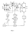
- An electrostatic filter 5 is fed in a manner known per se from a high-voltage rectifier device 6 which is connected to the network RS.
- a control device 7 is provided which is not the subject of the invention and is described, for example, in more detail in the abovementioned literature reference "Siemens Journal".
- a pulse voltage source which consists of the rectifier 1 fed from a three-phase network RST with optionally controllable semiconductor valves 11, a parallel supporting capacitor 12, a circuit arrangement 2 with anti-parallel connected thyristor 22 and diode 21 and a pulse transformer 3 with primary winding 31 and secondary winding 32.
- the pulse voltage Up which can be removed from the secondary winding 32, is fed to the electrostatic filter 5 via a coupling capacitor 4 and is connected to the filter 5 together with the direct voltage U gl coming from the high-voltage rectifier device.
- the thyristor 22 is assigned an ignition circuit 23, which is periodically spaced, for. B. at a periodic interval Tp of 2 ms, delivers ignition pulses to the thyristor 22.
- the series resonant circuit consisting of the pulse voltage source, ie the components 12, 31, 32, coupling capacitor 4 and electrostatic filter 5, is triggered.
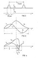
- the primary current denoted by i in FIG. 3 flows through the primary winding 31 and induces the pulse voltage denoted Up in the secondary winding 32.
- the superimposition of the pulse voltage Up and the high DC voltage U gl then results overall in the voltage profile shown in FIG. 2 on the electrostatic filter.
- the individual pulses have a voltage duration of 200 microseconds.
- the oscillation in the primary circuit runs in normal operation in such a way that after the thyristor 22 is fired, this thyristor initially carries the current denoted i T until the current is taken over by the diode 21 after the zero crossing.
- the current i D which forms the second part of the oscillation of the primary current i, then flows through this diode. Is the diode current i o again through zero, the oscillation is terminated, initiated again by a firing pulse to the thyristor 22 to the oscillation circuit.
- the thyristor 22 would fire again, even without an ignition pulse. However, this process would take a relatively long time, so that the thyristor is thermally overloaded.
- the time period t x is therefore monitored, in which flows the diode current i D , ie the second half-wave of the primary current. If this time t x is less than the release time tq of the thyristor 22, it is immediately triggered again by an ignition pulse so that it can again take over the current. Since the DC voltage at the electrostatic filter was also reduced to zero as a result of the short circuit, this additional voltage pulse has no major effect.
- a square-wave signal is generated in a flip-flop 82, the width t x of which corresponds to the distance between the zero crossings of the current i D.
- This signal triggers a monostable multivibrator 83 which tilts back again within a time which is approximately the Freiwerdezei tt q of the thyristor 22 s t - speaks.
- the output signal of this flip-flop together with the output signal of the flip-flop 82 are applied to a logic circuit 84, in which a comparison is made as to whether that is the current flow duration t.
- a logic circuit 84 responds and inputs a memory 85 Set signal.
- This memory gives via line 86 to the ignition circuit 23 an immediate command to ignite the thyristor 22 and then blocks the delivery of further ignition pulses by the ignition circuit 23 for a time dependent on the filter operating values. B. be made such that when the DC voltage at the filter has reached a certain level again through the control 7, the memory 85 is implemented and the ignition circuit 23 is thereby released.
Landscapes
- Engineering & Computer Science (AREA)
- Automation & Control Theory (AREA)
- Electrostatic Separation (AREA)
- Power Conversion In General (AREA)
- Electrical Discharge Machining, Electrochemical Machining, And Combined Machining (AREA)
- Surgical Instruments (AREA)
- Rectifiers (AREA)
Description
- Die Erfindung bezieht sich auf eine Einrichtung nach dem Oberbegriff des Hauptanspruches.
- Im Regel fall werden heute Elektrofilter mit hoher Gleichspannung betrieben, die durch Gleichrichtung aus einem Wechselspannungsnetz erzeugt wird (vgl. z. B. Siemens-Zeitschrift 1971, Heft 9, S. 567-572). Es ist bekannt, dieser in Abhängigkeit von Filterkurzschlüssen regelbaren Gleichspannung noch weitere Spannungsimpulse zu überlagern (vgl. z. B. DE-OS Nrn. 2608436 oder 3027172).
- Es sind ferner bereits Pulsspannungsquellen zur Lieferung der Pulsspannung bekannt, bei der an eine Gleichspannungsquelle eine Antiparallelschaltung von Thyristor und Diode angeschlossen ist. Beim Zünden des Thyristors wird jedesmal der durch den Abscheider in Verbindung mit der Pulsspannungsquelle gebildete Schwingkreis angestossen (vgl. z. B. DE-OS Nr. 2608436).
- Beim Elektrofilter tritt normalerweise der Überschlag im Maximum oder kurz nach dem Maximum der Filterspannung auf, d. h. in der Zeitperiode, in der die Diode den Impulsstrom führt. Durch den Kurzschluss reisst nun die Schwingung sofort ab, d. h. die Diodesperrt. Damit liegt sofort wieder die volle Spannung am antiparallelgeschalteten Thyristor. Ist die Zeitdauer zwischen Löschung des Thyristors durch den Nulldurchgang des Stromes und Übernahme des Stromes durch die Diode sehr gering, d. h. geringer als die Freiwerdezeit des Thyristors, so kann der Thyristor durch die wiederkehrende Spannung auch ohne Zündimpuls zünden. Da diese Zündung relativ langsam vonstatten geht, wird der Thyristor während dieser Zeit thermisch sehr hoch belastet und unter Umständen zerstört.
- Die Aufgabe der vorliegenden Erfindung besteht darin, bei einer Einrichtung der eingangs genannten Artdafür zu sorgen, dass bei einem Überschlag oder Kurzschluss im Elektrofilter der Thyristor oder gegebenenfalls eine Reihen- und/oder Parallelschaltung. von Thyristoren nicht beschädigt wird. Diese Aufgabe wird gemäss den kennzeichnenden Merkmalen des Hauptanspruches gelöst. Auf diese Weise wird die im Thyristor auftretende Verlustleistung begrenzt.
- Vorteilhafte Ausgestaltungen der Erfindung sind in den Unteransprüchen beschrieben.
- Anhand einer Zeichnung sei die Erfindung näher erläutert. Es zeigen:
- Fig. 1 ein Prinzipschaltbild der Spannungsversorgung,
- Fig. 2 den Verlauf der Spannung am Abscheider bei ungestörtem Filterbetrieb,
- Fig. 3 in vergrössertem Massstab den primärseitigen Impulsstrom und die sekundärseitige Pulsspannung, und
- Fig. 4 die Spannungs- und Stromverhältnisse nach Fig. 3 bei einem Überschlag im Filter.
- Ein Elektrofilter 5 wird in an sich bekannter Weise aus einem Hochspannungsgleichrichtergerät 6 gespeist, das an das Netz RS angeschlossen ist. Zur Regelung der Ausgangsspannung des Elektrofilters 5 in Abhängigkeit von Überschlägen, Überstrom usw. ist eine Regeleinrichtung 7 vorgesehen, die nicht Gegenstand der Erfindung ist und beispielsweise näher in der vorgenannten Literaturstelle "Siemens-Zeitschrift" beschrieben ist.
- Zusätzlich ist noch eine Pulsspannungsquelle vorgesehen, die aus dem aus einem Drehstromnetz RST gespeisten Gleichrichter 1 mit gegebenenfalls steuerbaren Halbleiterventilen 11, einem parallelgeschalteten Stützkondensator 12, einer Schaltungsanordnung2mitantiparallelgeschalte- tem Thyristor 22 und Diode 21 und einem Impulstransformator 3 mit Primärwicklung 31 und Sekundärwicklung 32 besteht. Die an der Sekundärwicklung 32 abnehmbare Pulsspannung Up wird über einen Koppelkondensator 4 dem Elektrofilter 5 zugeführt und liegt zusammen mit der vom Hochspannungsgleichrichtergerät kommenden Gleichspannung Ugl am Filter 5.
- Dem Thyristor 22 ist eine Zündschaltung 23 zugeordnet, die in periodischen Abständen, z. B. in einem periodischen Abstand Tp von 2 ms, Zündimpulse an den Thyristor 22 liefert. Hierdurch wird der aus der Pulsspannungsquelle, d. h. den Bauteilen 12,31, 32, Koppelkondensator 4 und Elektrofilter 5 bestehende Reihenschwingkreis angestossen. Hier durchfliesstder mit i, in Fig. 3 bezeichnete Primärstrom die Primärwicklung 31 und induziert in der Sekundärwicklung 32 die mit Up bezeichnete Pulsspannung. Die Überlagerung der Pulsspannung Up und der Hochgleichspannung Ugl ergibt dann insgesamt den in Fig. 2 gezeigten Spannungsverlauf am Elektrofilter, wobei z. B. die einzelnen Pulse eine Spannungsdauer von 200 µs haben.
- Die Schwingung im Primärkreis verläuft im Normalbetrieb in der Weise, dass nach dem Zünden des Thyristors 22 zunächst dieser Thyristor den mit iT bezeichneten Strom führt, bis nach dem Nulldurchgang der Strom von der Diode 21 übernommen wird. Durch diese Diode fliesst dann der Strom iD, der den zweiten Teil der Schwingung des Primärstromes i, bildet. Geht der Diodenstrom io wieder durch Null, so ist die Schwingung beendet, bis der Schwingungskreis wieder durch einen Zündimpuls an den Thyristor 22 angestossen wird.
- In Fig. 4 sind die Verhältnisse bei einem Kurzschluss dargestellt. Wie ersichtlich, bricht zum Zeitpunkt tk infolge eines Überschlages die Spannung Up zusammen und wird zu Null. Durch den Überschlag sperrt auch die Diode, so dass der Diodenstrom iD ebenfalls nach Null geht und die Schwingung abreisst. Dies hat zur Folge, dass sofort wieder die volle Gleichspannung am Thyristor 22 liegt. Ist die Zeit, in der der Diodenstrom fliesst, grösser als die Freiwerdezeit des Thyristors 22, so zündet dieser nicht mehr. Anders ist es dagegen, wenn die Zeit tx bis zum Verschwinden des Diodenstromes iD kleiner ist als die erforderliche Freiwerdezeit tq des Thyristors 22. In einem solchen Fall würde der Thyristor 22 wieder zünden, und zwar auch ohne Zündimpuls. Dieser Vorgang würde jedoch relativ lang dauern, so dass der Thyristor thermisch überbelastetwird. Erfindungsgemäss wird daher die Zeitdauer tx überwacht, in der der Diodenstrom iD, d. h. die zweite Halbwelle des Primärstromes, fliesst. Ist diese Zeit tx kleiner als die Freiwerdezeit tq des Thyristors 22, so wird dieser sofort wieder durch einen Zündimpuls gezündet, so dass er wieder den Strom übernehmen kann. Da infolge des Kurzschlusses auch die Gleichspannung am Elektrofilter auf Null reduziert wurde, ist dieser zusätzliche Spannungsimpuls ohne grössere Auswirkung.
- Wie aus Fig. 1 ersichtlich, wird zum Zwecke der Überwachung der Diodenstrom iD erfasst. Hieraus wird ein Rechtecksignal in einer Kippschaltung 82 erzeugt, dessen Breite tx dem Abstand der Nulldurchgänge des Stromes iD entspricht. Dieses Signal stösst eine monostabile Kippstufe 83 an, die innerhalb einer Zeit wieder zurückkippt, die in etwa der Freiwerdezeit tq des Thyristors 22 ent- spricht. Das Ausgangssignal dieser Kippstufe zusammen mit dem Ausgangssignal der Kippstufe 82 liegen an einer Logikschaltung 84, in der verglichen wird, ob das der Stromflussdauer t. entsprechende Signal grösser oder kleiner ist als die in der monostabilen Kippstufe 83 eingestellte Freiwerdedauer tq. Steht das Ausgangssignal der monostabilen Kippstufe 83 noch an, während das Ausgangssignal der Stufe 82 bereits verschwunden ist, d. h. ist die Dauer tx zwischen den Nulldurchgängen des Diodenstromes geringer als die Freiwerdezeit tq, so spricht eine Logikschaltung 84 an und gibt auf einen Speicher 85 ein Setzsignal. Dieser Speicher gibt über Leitung 86 an die Zündschaltung 23 einen sofortigen Befehl zur Zündung des Thyristors 22 und blockiert dann für eine von den Filterbetriebswerten abhängige Zeit die Abgabe weiterer Zündimpulse durch die Zündschaltung 23. Die erneute Freigabe der Zündschaltung 23 kann dabei z. B. so getroffen werden, dass, wenn durch die Regelung 7 die Gleichspannung am Filter wieder ein bestimmtes Mass erreicht hat, das Gedächtnis 85 umgesetzt wird und die Zündschaltung 23 dadurch freigegeben wird.
- Zusätzlich ist es auch noch möglich, die Zahl der pro Zeiteinheit anfallenden zusätzlichen Zündimpulse in einem Zähler 9 zu summieren und, wie durch Leitung 91 angedeutet, gegebenenfalls sodann die Pulsfrequenz zu ändern. Alternativ ist es auch möglich, die Amplitude der Pulse durch entsprechende Aussteuerung des Gleichrichtergerätes 1 und/oder die Höhe der Gleichspannung durch entsprechende Aussteuerung des Hochspannungsgleichrichtergerätes 6 zu verändern.
Claims (4)
Priority Applications (1)
| Application Number | Priority Date | Filing Date | Title |
|---|---|---|---|
| AT83112096T ATE18514T1 (de) | 1982-12-13 | 1983-12-01 | Einrichtung zur spannungsversorgung eines elektrofilters. |
Applications Claiming Priority (2)
| Application Number | Priority Date | Filing Date | Title |
|---|---|---|---|
| DE19823246057 DE3246057A1 (de) | 1982-12-13 | 1982-12-13 | Einrichtung zur spannungsversorgung eines elektrofilters |
| DE3246057 | 1982-12-13 |
Publications (2)
| Publication Number | Publication Date |
|---|---|
| EP0111794A1 EP0111794A1 (de) | 1984-06-27 |
| EP0111794B1 true EP0111794B1 (de) | 1986-03-12 |
Family
ID=6180508
Family Applications (1)
| Application Number | Title | Priority Date | Filing Date |
|---|---|---|---|
| EP83112096A Expired EP0111794B1 (de) | 1982-12-13 | 1983-12-01 | Einrichtung zur Spannungsversorgung eines Elektrofilters |
Country Status (5)
| Country | Link |
|---|---|
| US (1) | US4873620A (de) |
| EP (1) | EP0111794B1 (de) |
| JP (1) | JPS59115758A (de) |
| AT (1) | ATE18514T1 (de) |
| DE (2) | DE3246057A1 (de) |
Families Citing this family (12)
| Publication number | Priority date | Publication date | Assignee | Title |
|---|---|---|---|---|
| JP2561453B2 (ja) * | 1983-02-07 | 1996-12-11 | 住友重機械工業株式会社 | 電気集塵機用パルス電源 |
| DE3511622A1 (de) * | 1985-03-29 | 1986-10-09 | Metallgesellschaft Ag, 6000 Frankfurt | Verfahren und einrichtung zur versorgung eines elektroabscheiders mit hochspannungsimpulsen |
| DE3640092A1 (de) * | 1986-11-24 | 1988-06-01 | Metallgesellschaft Ag | Verfahren und einrichtung zur energieversorgung eines elektroabscheiders |
| DK0534950T3 (da) * | 1990-04-04 | 1995-12-18 | Siemens Ag | Reguleringsfremgangsmåde til strømforsyningsindretningen i et elektrofilter |
| US5542967A (en) * | 1994-10-06 | 1996-08-06 | Ponizovsky; Lazar Z. | High voltage electrical apparatus for removing ecologically noxious substances from gases |
| US6063168A (en) * | 1997-08-11 | 2000-05-16 | Southern Company Services | Electrostatic precipitator |
| JP4627165B2 (ja) * | 2004-09-02 | 2011-02-09 | 三菱電機株式会社 | 電力用半導体装置の制御用回路および制御用集積回路 |
| PL1652586T5 (pl) * | 2004-10-26 | 2016-08-31 | Smidth As F L | System wytwarzający impulsy dla odpylacza elektrostatycznego |
| US20070156051A1 (en) * | 2005-12-29 | 2007-07-05 | Amit Pascal | Device and method for in-vivo illumination |
| US10734257B2 (en) * | 2012-04-25 | 2020-08-04 | Applied Materials, Inc. | Direct current lamp driver for substrate processing |
| WO2015188837A1 (en) * | 2014-06-13 | 2015-12-17 | Flsmidth A/S | Controlling a high voltage power supply for an electrostatic precipitator |
| CN111565853B (zh) * | 2017-10-09 | 2022-09-27 | 夸普瑞典公司 | 高压电源系统 |
Family Cites Families (10)
| Publication number | Priority date | Publication date | Assignee | Title |
|---|---|---|---|---|
| JPS4831015B1 (de) * | 1969-01-08 | 1973-09-26 | ||
| DE1923952C3 (de) * | 1969-05-10 | 1980-04-30 | Licentia Patent-Verwaltungs-Gmbh, 6000 Frankfurt | Regelvorrichtung für einen Elektroabscheider zum elektrostatischen Abscheiden von Aerosolen, insbesondere für die Abgasentstaubung |
| SE364826B (de) * | 1972-07-10 | 1974-03-04 | Asea Ab | |
| DK150012C (da) * | 1975-03-03 | 1992-05-25 | Smidth & Co As F L | Elektrisk kobling til et elektrostatisk filter |
| JPS51116663A (en) * | 1975-04-07 | 1976-10-14 | Hitachi Ltd | Gate control unit for thyrister valve |
| DE2713675C2 (de) * | 1977-03-28 | 1984-08-23 | Siemens AG, 1000 Berlin und 8000 München | Stromversorgung für einen Elektroabscheider |
| JPS55141982A (en) * | 1979-04-24 | 1980-11-06 | Toshiba Corp | Gate circuit for thyristor converter |
| SE446418B (sv) * | 1980-07-07 | 1986-09-08 | Asea Ab | Aterhemtningsskydd for en tyristorventil med ett flertal seriekopplade tyristorer |
| DE3027172A1 (de) * | 1980-07-17 | 1982-02-18 | Siemens AG, 1000 Berlin und 8000 München | Verfahren zum betrieb eines elektrofilters |
| NL8103474A (nl) * | 1981-07-23 | 1983-02-16 | Hollandse Signaalapparaten Bv | Energieomzetter. |
-
1982
- 1982-12-13 DE DE19823246057 patent/DE3246057A1/de not_active Withdrawn
-
1983
- 1983-11-10 US US06/550,616 patent/US4873620A/en not_active Expired - Fee Related
- 1983-12-01 EP EP83112096A patent/EP0111794B1/de not_active Expired
- 1983-12-01 AT AT83112096T patent/ATE18514T1/de not_active IP Right Cessation
- 1983-12-01 DE DE8383112096T patent/DE3362565D1/de not_active Expired
- 1983-12-08 JP JP58232609A patent/JPS59115758A/ja active Granted
Non-Patent Citations (1)
| Title |
|---|
| SIEMENS-ZEITSCHRIFT, Band 45, Heft 9, September 1971, ERLANGEN (DE), A. GOLLER et al.: "Elektrofiltersteuerung mit direkter Durchbruchserfassung", Seiten 567-572 * |
Also Published As
| Publication number | Publication date |
|---|---|
| DE3362565D1 (en) | 1986-04-17 |
| US4873620A (en) | 1989-10-10 |
| EP0111794A1 (de) | 1984-06-27 |
| DE3246057A1 (de) | 1984-06-14 |
| JPS59115758A (ja) | 1984-07-04 |
| JPS6110181B2 (de) | 1986-03-28 |
| ATE18514T1 (de) | 1986-03-15 |
Similar Documents
| Publication | Publication Date | Title |
|---|---|---|
| EP0268934B1 (de) | Verfahren und Einrichtung zur Energieversorgung eines Elektroabscheiders | |
| DE69206182T2 (de) | Hochfrequenz-Kommutationstyp geschützt durch Leistungsversorgung, insbesondere für elektrostatische Abscheider. | |
| DE3133883A1 (de) | "geregelte stromversorgungseinheit" | |
| DE3779850T2 (de) | Laservorrichtung mit hochspannungsimpulsgenerator, hochspannungsimpulsgenerator und verfahren zur impulserzeugung. | |
| DE69400861T2 (de) | Elektro-Abscheider | |
| DE3884258T2 (de) | Leistungsversorgung für Magnetron. | |
| WO1994015444A1 (de) | Vorschaltgerät für mindestens ein parallel betriebenes gasentladungslampen-paar | |
| DE3323400C2 (de) | Stromversorgungsschaltung für eine elektromagnetische Betätigungsvorrichtung | |
| EP0111794A1 (de) | Einrichtung zur Spannungsversorgung eines Elektrofilters | |
| DE3927888A1 (de) | Wechselrichteranordnung | |
| DE2824326C2 (de) | ||
| DE3403619A1 (de) | Elektrische stromversorgungsquelle fuer die verwendung in einer elektrostatischen ausfaellvorrichtung | |
| DE2232625A1 (de) | Gleichstrom/gleichstrom-umformerschaltung | |
| DE3607414C2 (de) | ||
| CH656818A5 (de) | Energiezuliefereinheit fuer eine funkenerosionsmaschine. | |
| EP0060992A2 (de) | Prüf- und Auswerteschaltung für Näherungsschalter in Maschinensteuerungen | |
| EP0197369B1 (de) | Verfahren und Einrichtung zur Versorgung eines Elektroabscheiders mit Hochspannungsimpulsen | |
| DE69513646T2 (de) | Schaltung zum Betreiben von Entladungslampen mit vorgeheizten Wendeln | |
| DE2526649C3 (de) | Erdschlußschutzeinrichtung | |
| DE4235766C1 (de) | Koronagenerator | |
| EP0015304B1 (de) | Verfahren und Vorrichtung zum Aufladen eines Kondensators | |
| DE2745417C2 (de) | Schaltung zum Erzeugen eines sägezahnförmigen Stroms in einer Spule | |
| DE2950092C2 (de) | Anordnung zum gleichzeitigen Zünden einer Vielzahl von in Reihe geschalteten Thyristoren | |
| DE69225289T2 (de) | Energieversorungseinrichtung eines Ozonerzeugers | |
| EP0211300A2 (de) | Schaltnetzteil |
Legal Events
| Date | Code | Title | Description |
|---|---|---|---|
| PUAI | Public reference made under article 153(3) epc to a published international application that has entered the european phase |
Free format text: ORIGINAL CODE: 0009012 |
|
| AK | Designated contracting states |
Designated state(s): AT CH DE FR GB LI SE |
|
| 17P | Request for examination filed |
Effective date: 19840726 |
|
| GRAA | (expected) grant |
Free format text: ORIGINAL CODE: 0009210 |
|
| AK | Designated contracting states |
Kind code of ref document: B1 Designated state(s): AT CH DE FR GB LI SE |
|
| REF | Corresponds to: |
Ref document number: 18514 Country of ref document: AT Date of ref document: 19860315 Kind code of ref document: T |
|
| REF | Corresponds to: |
Ref document number: 3362565 Country of ref document: DE Date of ref document: 19860417 |
|
| ET | Fr: translation filed | ||
| PLBE | No opposition filed within time limit |
Free format text: ORIGINAL CODE: 0009261 |
|
| STAA | Information on the status of an ep patent application or granted ep patent |
Free format text: STATUS: NO OPPOSITION FILED WITHIN TIME LIMIT |
|
| 26N | No opposition filed | ||
| EAL | Se: european patent in force in sweden |
Ref document number: 83112096.9 |
|
| PGFP | Annual fee paid to national office [announced via postgrant information from national office to epo] |
Ref country code: DE Payment date: 19950217 Year of fee payment: 12 |
|
| PGFP | Annual fee paid to national office [announced via postgrant information from national office to epo] |
Ref country code: CH Payment date: 19950317 Year of fee payment: 12 |
|
| PGFP | Annual fee paid to national office [announced via postgrant information from national office to epo] |
Ref country code: GB Payment date: 19951123 Year of fee payment: 13 |
|
| PGFP | Annual fee paid to national office [announced via postgrant information from national office to epo] |
Ref country code: AT Payment date: 19951129 Year of fee payment: 13 |
|
| PGFP | Annual fee paid to national office [announced via postgrant information from national office to epo] |
Ref country code: SE Payment date: 19951221 Year of fee payment: 13 |
|
| PGFP | Annual fee paid to national office [announced via postgrant information from national office to epo] |
Ref country code: FR Payment date: 19951226 Year of fee payment: 13 |
|
| PG25 | Lapsed in a contracting state [announced via postgrant information from national office to epo] |
Ref country code: LI Effective date: 19951231 Ref country code: CH Effective date: 19951231 |
|
| REG | Reference to a national code |
Ref country code: CH Ref legal event code: PL |
|
| PG25 | Lapsed in a contracting state [announced via postgrant information from national office to epo] |
Ref country code: DE Effective date: 19960903 |
|
| PG25 | Lapsed in a contracting state [announced via postgrant information from national office to epo] |
Ref country code: GB Effective date: 19961201 Ref country code: AT Effective date: 19961201 |
|
| PG25 | Lapsed in a contracting state [announced via postgrant information from national office to epo] |
Ref country code: SE Effective date: 19961202 |
|
| GBPC | Gb: european patent ceased through non-payment of renewal fee |
Effective date: 19961201 |
|
| PG25 | Lapsed in a contracting state [announced via postgrant information from national office to epo] |
Ref country code: FR Effective date: 19970829 |
|
| EUG | Se: european patent has lapsed |
Ref document number: 83112096.9 |
|
| REG | Reference to a national code |
Ref country code: FR Ref legal event code: ST |