EP0111195A2 - Gun ammunition, especially for high trajectory firing - Google Patents
Gun ammunition, especially for high trajectory firing Download PDFInfo
- Publication number
- EP0111195A2 EP0111195A2 EP83111589A EP83111589A EP0111195A2 EP 0111195 A2 EP0111195 A2 EP 0111195A2 EP 83111589 A EP83111589 A EP 83111589A EP 83111589 A EP83111589 A EP 83111589A EP 0111195 A2 EP0111195 A2 EP 0111195A2
- Authority
- EP
- European Patent Office
- Prior art keywords
- propellant charge
- partial
- charge
- ammunition
- housing
- Prior art date
- Legal status (The legal status is an assumption and is not a legal conclusion. Google has not performed a legal analysis and makes no representation as to the accuracy of the status listed.)
- Granted
Links
Images
Classifications
-
- F—MECHANICAL ENGINEERING; LIGHTING; HEATING; WEAPONS; BLASTING
- F42—AMMUNITION; BLASTING
- F42C—AMMUNITION FUZES; ARMING OR SAFETY MEANS THEREFOR
- F42C19/00—Details of fuzes
- F42C19/08—Primers; Detonators
- F42C19/0823—Primers or igniters for the initiation or the propellant charge in a cartridged ammunition
- F42C19/083—Primers or igniters for the initiation or the propellant charge in a cartridged ammunition characterised by the shape and configuration of the base element embedded in the cartridge bottom, e.g. the housing for the squib or percussion cap
-
- F—MECHANICAL ENGINEERING; LIGHTING; HEATING; WEAPONS; BLASTING
- F42—AMMUNITION; BLASTING
- F42B—EXPLOSIVE CHARGES, e.g. FOR BLASTING, FIREWORKS, AMMUNITION
- F42B5/00—Cartridge ammunition, e.g. separately-loaded propellant charges
- F42B5/02—Cartridges, i.e. cases with charge and missile
-
- F—MECHANICAL ENGINEERING; LIGHTING; HEATING; WEAPONS; BLASTING
- F42—AMMUNITION; BLASTING
- F42B—EXPLOSIVE CHARGES, e.g. FOR BLASTING, FIREWORKS, AMMUNITION
- F42B5/00—Cartridge ammunition, e.g. separately-loaded propellant charges
- F42B5/02—Cartridges, i.e. cases with charge and missile
- F42B5/08—Cartridges, i.e. cases with charge and missile modified for electric ignition
Definitions
- the invention relates to ammunition according to the preamble of claim 1.
- Such ammunition is the subject of European patent application 0081 644 A3 with application number 82 109 259.0. With it, the range of the projectile for a given propellant charge is determined exclusively by the pipe elevation. This limitation can be annoying.
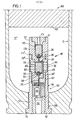
- a propellant charge sleeve 11 encloses an interior 11 'with a base 12.
- a housing 51 of an ignition device 50 with an external thread 58 is screwed into a bottom-side opening 13 with an internal thread 14.
- the housing 51 encloses an insulating tube 52, which in turn encloses a contact pin 53.
- a potting compound 55 essentially fills a space in the housing 51 and extends to a grid 54, on which a spacer plate 56 rests.
- a housing 32 for a partial propellant charge 30 is screwed into an internal thread 57 by means of an external thread 32 ′ in the housing 51.
- a housing 22 for a partial propellant charge 20 is screwed into an internal thread 32 ′′ by means of an external thread 22 ′ in the housing 32.
- the partial propellant charge 20 is encased by a charge capsule 29, the partial propellant charge 30 is encased by a charge capsule 40.
- a line 25 connects the contact pin 53 with an igniter 28 for the propellant charge 20.
- a sealing plate 27 is arranged in the immediate vicinity of the igniter 28.
- the encased partial propellant charge 20 is in continuous connection with the interior 11 'via outlet openings 23'.
- the housing 32 points to the continuous connection of the charge capsule 40 with the interior 11 'exit openings 33. The latter are pressure-tightly closed in the direction of the partial propellant charge 30 by means of a respective closure element 34.
- a line 35 connects the contact pin 53 to an igniter pill 39 for the partial propellant charge 30. In the immediate vicinity of the igniter pill 39 is a sealing plate 38. In line 35 left a defined ballast resistor 36. As a result, an ignition circuit of the partial propellant charge 30 has a greater resistance than an ignition circuit of the partial propellant charge 20.
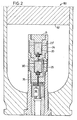
- FIG. 2 differs from that according to FIG. 1 essentially by closure elements 24 assigned to outlet openings 23 ′.
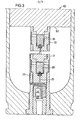
- the further partial propellant charge 30 is fastened to the tiller 62 of the projectile 60. If only the first partial propellant charge 20 is ignited, the non-ignited partial propellant charge 30 leaves the weapon barrel with the projectile 60. When both partial propellant charges 20 and 30 are ignited, the burned-out housing 32 remains on the floor 62.
- the first partial propellant charge is to be ignited mechanically, it is located in the immediate vicinity of the ignition device 50.
- the advantage of the invention is the adaptability of the muzzle velocity to the respective circumstances. It is clear from this that in addition to the partial propellant charges 20 and 30, further partial propellant charges vqrhan that can be. Advantageously, no manipulation needs to be vorillonv at the ammunition for election to the muzzle velocity. The choice can also be made if the ammunition unit is already in the cargo area and a lock is locked.
Abstract
Die Treibladung 10 ist in eine erste Teiltreibladung 20 und eine weitere Teiltreibladung 30 unterteilt. Jeder Teiltreibladung ist ein Gehäuse 22, 32 mit Austrittsöffnungen 23, 33 und eine Anzündleitung 25, 35 zugeordnet. In der Anzündleitung 35 liegt ein Vorschaltwiderstand 36. Die Anzündleitungen 25, 35 verbinden einen Kontaktstift 53 mit einer jeweiligen Anzündpille 28, 29. Soll nur die erste Teiltreibladung 20 angezündet werden, wird eine vergleichsweise geringe Anzündspannung an den Kontaktstift 23 angelegt. Hieraus resultiert eine der Teiltreibladung 20 entsprechende Mündungsgeschwindigkeit. Soll die Mündungsgeschwindigkeit größer sein, wird auch die Teiltreibladung 30 angezündet. Wegen des Vorschaltwiderstandes 36 muß dann die Anzündspannung höher sein.The propellant charge 10 is divided into a first sub-propellant charge 20 and a further sub-propellant charge 30. A housing 22, 32 with outlet openings 23, 33 and an ignition line 25, 35 is assigned to each partial propellant charge. A series resistor 36 is located in the ignition line 35. The ignition lines 25, 35 connect a contact pin 53 to a respective ignition pill 28, 29. If only the first partial propellant charge 20 is to be ignited, a comparatively low ignition voltage is applied to the contact pin 23. This results in a muzzle velocity corresponding to the partial propellant charge 20. If the muzzle velocity is to be greater, the partial propellant charge 30 is also ignited. Because of the series resistor 36, the ignition voltage must then be higher.
Description
Die Erfindung betrifft Munition nach dem Oberbegriff des Patentanspruchs 1. Derartige Munition ist Gegenstand der Europa-Patentanmeldung 0081 644 A3 mit der Anmeldenummer 82 109 259.0. Bei ihr wird die Reichweite des Geschosses bei vorgegebener Treibladung ausschließlich durch die Rohrerhöhung bestimmt. Diese Einschränkung kann sich als störend erweisen.The invention relates to ammunition according to the preamble of
Deshalb liegt der Erfindung die Aufgabe zugrunde, eine Muni- tion der eingangs genannten Gattung bereitzustellen, deren Reichweitenveränderlichkeit wenigstens teilweise von der Rohrerhöhung unabhängig ist.It is therefore the object of the invention to provide an M unation of the type mentioned at the outset, whose range variability is at least partially independent of the pipe elevation.
Gelöst wird diese Aufgabe durch die im Kennzeichen des Patentanspruchs 1 angegebene Erfindung, die nach-stehend anhand dreier in der Zeichnung dargestellter, bevorzugter Ausführungsbeispiele näher erläutert wird.This object is achieved by the invention specified in the characterizing part of
Es zeigen, jeweils in einem längsachsialen Schnitt durch einen rückseitigen Bereich einer betreffenden Munitionseinheit, d. h. ausschnittweise, die Figuren 1, 2 und 3 je eines der drei Ausführunqsheispiele.They show, in each case in a longitudinal axial section through a rear area of a relevant ammunition unit, i. H. excerpts, Figures 1, 2 and 3 each one of the three exemplary embodiments.
Gemäß Fig. 1 umschließt eine Treibladungshülse 11 mit einem Boden 12 einen Innenraum 11'. In eine bodenseitige Öffnung 13 mit einem Innengewinde 14 ist ein Gehäuse 51 einer Anzündeinrichtung 50 mit einem Außengewinde 58 eingeschraubt. Das Gehäuse 51 umschließt ein Isolierrohr 52, das seinerseits einen Kontaktstift 53 umschließt. Eine Vergußmasse 55 füllt im wesentlichen einen Raum im Gehäuse 51 aus und erstreckt sich bis zu einem Gitter 54, dem ein Distanzplättchen 56 aufliegt. In ein Innengewinde 57 ist ein Gehäuse 32 für eine Teiltreibladung 30 mittels eines Außengewindes 32' in das Gehäuse 51 eingeschraubt. In ein Innengewinde 32 "ist ein Gehäuse 22 für eine Teiltreibladung 20 mittels eines Außengewindes 22' in das Gehäuse 32 eingeschraubt. Die Teiltreibladung 20 ist-von einer Ladungskapsel 29, die Teiltreibladung 30 ist von einer Ladungskapsel 40 eingehüllt. Eine Leitung 25 verbindet den Kontaktstift 53 mit einer Anzündpille 28 für die Treibladunq 20. In nächster Nachbarschaft der Anzündpille 28 ist ein Dichtplättchen 27 angeordnet. Über Austrittsöffnunqen 23' steht die eingehültte Teiltreibladung 20 mit dem Innenraum 11' in durchgängiger Verbindung. Das Gehäuse 32 weist zur durchgängigen Verbindung der Ladungskapsel 40 mit dem Innenraum 11' Austrittsöffnungen 33 auf. Letztere sind mittels eines jeweiligen Verschlußelements 34 in Richtung auf die Teiltreibladung 30 druckfest verschlossen. Eine Leitung 35 verbindet den Kontaktstift 53 mit einer Anzündpille 39 für die Teiltreibladung 30. In nächster Nachbarschaft der Anzündpille 39 ist ein Dichtplättchen 38 angeordnet. In der Leitung 35 liegt ein definierter Vorschaltwiderstand 36. Hierdurch weist ein Anzündkreis der Teiltreibladung 30 einen größeren Widerstand auf als ein Anzündkreis der Teiltreibladung 20.1, a
Die Wirkungsweise ergibt sich folgendermaßen, wobei zunächst davon ausgegangen wird, daß nur die erste Teiltreibladung 20 angezündet werden soll:
- Eine Anzündspannung wird waffenseitig an den
Kontaktstift 53 angelegt, die für denVorschaltwiderstand 36 zu gering ist und deshalb nur dieTeiltreibladung 20 anzündet. Durch den hierbei im Innenraum 11' ent- stehenden Druck wirken dieVerschlußelemente 34 abschirmend auf dieTeiltreibladung 30. DasGeschoß 60 verläßt mit einer derTeiltreibladung 20 entsprechenden Mündungsgeschwindigkeiten das Waffenrohr. Hierauf kann durch Anlegen einer höheren Spannung dieTeiltreibladung 30 nachträglich gezündet werden, ohne noch Wirkung auf dasGeschoß 60 zu haben. DieTeiltreibladung 30 kann auch ohne angezüdet zu werden mit derTeiltreibladungshülse 11 aus dem Rohr der Waffe ausgezogen werden.
- An ignition voltage is applied to the
contact pin 53 on the weapon side, which is too low for theseries resistor 36 and therefore only ignites thepartial propellant charge 20. By this' e nt in theinterior 11 of stationary pressure theclosure elements 34act shielding 30 on the part of the propellant charge Theprojectile 60 leaves a part of thepropellant charge 20 corresponding to the weapon barrel muzzle velocities. Thepartial propellant charge 30 can then be ignited subsequently by applying a higher voltage without having any effect on theprojectile 60. Thepartial propellant charge 30 can also be pulled out of the barrel of the weapon with the partialpropellant charge sleeve 11 without being lit.
Soll das Geschoß 60 mit einer vergleichsweise höheren Mündungsgeschwindigkeit abgefeuert werden, wird eine ausreichend hohe Spannung aus einer waffenseitigen Spannungsquelle an den Kontaktstift 53 angelegt. Auf diese Weise werden beide Teiltreibladungen 20 und 30 angezündet.If the
Die Anordnung nach Fig. 2 unterscheidet sich von derjenigen nach Fig. 1 im wesentlichen durch Austrittsöffnunqen 23' zugeordnete Verschlußelemente 24.The arrangement according to FIG. 2 differs from that according to FIG. 1 essentially by
Bei der Anordnung nach Fig. 3 ist die weitere Teiltreibladung 30 am Roden 62 des Geschosses 60 befestiqt. Wird nur die erste Teiltreibladung 20 angezündet, verläßt die nicht angezündete Teiltreibladung 30 mit dem Geschoß 60 das Waffenrohr. Bei Anzündung beider Teiltreibladungen 20 und 30 verbleibt das ausgebrannte Gehäuse 32 am Geschoßboden 62. Bei einem nicht dargestellten Ausführungsbeispiel befindet sich die Teiltreibladung 30 mit ihrem Gehäuse 32 im Boden 62 des Geschosses 60.In the arrangement according to FIG. 3, the further
Soll die erste Teiltreibladung mechanisch angezündet werden, befindet sie sich in unmittelbarer Nachbarschaft der Anzündeinrichtung 50. Zum Anzünden der weiteren Teiltreibladung 30 muß abfeueurngsweise eine Anzündspannung angelegt werden.If the first partial propellant charge is to be ignited mechanically, it is located in the immediate vicinity of the ignition device 50.
Der Vorteil der Erfindung ist die Anpaßbarkeit der Mündungsgeschwindigkeit an jeweiliqe Gegebenheiten. Hieraus wird deutlich, daß außer den Teiltreibladunqen 20 und 30 noch weitere Teiltreibladungen vqrhanden sein können. Vorteilhafterweise braucht an der Munition zur Wahl zu der Mündungsgeschwindigkeit keine Manipulation vorgenommenvwerden. Die Wahl kann außerdem getroffen werden, wenn sich die Munitionseinheit bereits im Ladungsraum befindet und ein Verschluß verriegelt ist.The advantage of the invention is the adaptability of the muzzle velocity to the respective circumstances. It is clear from this that in addition to the partial propellant charges 20 and 30, further partial propellant charges vqrhan that can be. Advantageously, no manipulation needs to be vorgenommenv at the ammunition for election to the muzzle velocity. The choice can also be made if the ammunition unit is already in the cargo area and a lock is locked.
- 10 Treibladung10 propellant charge
- 11 Treibladungshülse11 propellant charge case
- 11' Innenraum11 'interior
- 12 Boden von 1112 floor of 11
- 13 Öffnung in 1213 opening in 12
- 14 Innengewinde in 1314 internal threads in 13
- 20 1. Teiltreibladung20 1st partial propellant charge
- 21 Verschlußschraube21 screw plug
- 22 Gehäuse22 housing
- 22' Gewinde22 'thread
- 23 Austrittsöffnung23 outlet opening
- 23' Austrittsöffnung23 'outlet opening
- 24 Verschlußelement24 closure element
- 25 Anzündleitung25 Ignition cable
- 26 Isolierkapsel26 insulating capsule
- 27 Dichtplättchen27 sealing plates
- 28 Anzündpille28 pill
- 29 Ladungskapsel29 charge capsule
- 30 weitere Teiltreibladung30 more partial propellant charges
- 32 Gehäuse32 housing
- 32' Gewinde32 ' thread
- 32' ' Gewinde .32 '' thread.
- 33 Austrittsöffnung33 outlet opening
- 34 Verschlußelement34 closure element
- 35 Anzündleitung35 Ignition cable
- 36 Vorschaltwiderstand36 ballast resistor
- 37 Isolierkapsel37 insulating capsule
- 38 Dichtplättchen38 sealing plates
- 39 Anzündpille39 pill
- 40 Ladungskapscl40 cargo capscl
- 50 Anzündeinrichtung50 igniter
- 51 Gehäuse51 housing
- 52 Isolierrohr52 insulating tube
- 53 Kontaktstift53 contact pin
- 54 Gitter54 grids
- 55 Vergußmasse55 potting compound
- 56 Distanzplättchen56 spacer tiles
- 57 Innengewinde57 internal thread
- 58 Außengewinde58 external thread
- 60 Geschoß60 storey
- 62 Geschoßboden62 floor
Claims (9)
Applications Claiming Priority (2)
| Application Number | Priority Date | Filing Date | Title |
|---|---|---|---|
| DE3246173 | 1982-12-14 | ||
| DE19823246173 DE3246173A1 (en) | 1982-12-14 | 1982-12-14 | AMMUNITION, ESPECIALLY FOR STEAP FIRE |
Publications (3)
| Publication Number | Publication Date |
|---|---|
| EP0111195A2 true EP0111195A2 (en) | 1984-06-20 |
| EP0111195A3 EP0111195A3 (en) | 1985-05-15 |
| EP0111195B1 EP0111195B1 (en) | 1987-09-09 |
Family
ID=6180582
Family Applications (1)
| Application Number | Title | Priority Date | Filing Date |
|---|---|---|---|
| EP83111589A Expired EP0111195B1 (en) | 1982-12-14 | 1983-11-19 | Gun ammunition, especially for high trajectory firing |
Country Status (7)
| Country | Link |
|---|---|
| US (1) | US4619202A (en) |
| EP (1) | EP0111195B1 (en) |
| JP (1) | JPS59109796A (en) |
| AU (1) | AU568520B2 (en) |
| CA (1) | CA1210276A (en) |
| DE (2) | DE3246173A1 (en) |
| ES (1) | ES526102A0 (en) |
Cited By (5)
| Publication number | Priority date | Publication date | Assignee | Title |
|---|---|---|---|---|
| FR2819882A1 (en) * | 2001-01-20 | 2002-07-26 | Rheinmetall W & M Gmbh | CARTRIDGE |
| WO2011160750A1 (en) * | 2010-06-23 | 2011-12-29 | Rheinmetall Waffe Munition Gmbh | Projectile |
| WO2012163470A1 (en) | 2011-06-01 | 2012-12-06 | Merck Patent Gmbh | Liquid crystal medium and liquid crystal display |
| EP2568032A2 (en) | 2011-09-06 | 2013-03-13 | Merck Patent GmbH | Liquid crystal medium and liquid crystal display |
| WO2013034219A1 (en) | 2011-09-06 | 2013-03-14 | Merck Patent Gmbh | Liquid crystal medium and liquid crystal display |
Families Citing this family (33)
| Publication number | Priority date | Publication date | Assignee | Title |
|---|---|---|---|---|
| DE3507758A1 (en) * | 1985-03-05 | 1986-09-18 | Obisco Textil Trading & Consulting S.A., Küsnacht | Handguns and shot ammunition here |
| DE3510367A1 (en) * | 1985-03-22 | 1986-09-25 | Nico-Pyrotechnik Hanns-Jürgen Diederichs GmbH & Co KG, 2077 Trittau | FOGGED BODY |
| US4823699A (en) * | 1987-04-14 | 1989-04-25 | Aai Corporation | Back-actuated forward ignition ammunition and method |
| ES2046044T3 (en) * | 1990-01-15 | 1994-01-16 | Udo Winter | CARTRIDGE, ESPECIALLY POMEGRANATE CARTRIDGE. |
| SE9002010L (en) * | 1990-06-06 | 1991-11-25 | Bofors Ab | BATTLE-INITIATED TUNER FOR ARTILLERY AMMUNITION |
| US5353710A (en) * | 1991-02-11 | 1994-10-11 | Giat Industries | Container fitted with electrical connecting means |
| US5263416A (en) * | 1992-02-06 | 1993-11-23 | Alliant Techsystems Inc. | Primer propellant electrical ignition interconnect arrangement for single and multiple piece ammunition |
| US5272828A (en) * | 1992-08-03 | 1993-12-28 | Colt's Manufacturing Company Inc. | Combined cartridge magazine and power supply for a firearm |
| US5421264A (en) * | 1992-09-15 | 1995-06-06 | Colt's Manufacturing Company Inc. | Firearm cartridge with pre-pressurizing charge |
| US5301448A (en) * | 1992-09-15 | 1994-04-12 | Colt's Manufacturing Company Inc. | Firearm safety system |
| US5631439A (en) * | 1995-06-07 | 1997-05-20 | Tracor Aerospace, Inc. | Multiple squib assembly |
| DE19653784A1 (en) * | 1996-12-21 | 1998-06-25 | Dynamit Nobel Ag | Non-lethal weapon |
| US5880397A (en) * | 1997-10-23 | 1999-03-09 | Scientific Solutions Inc. | Selectable cartridge |
| DE19834058C2 (en) * | 1998-07-29 | 2001-08-23 | Rheinmetall W & M Gmbh | Propellant charge |
| FR2792399B1 (en) | 1999-04-19 | 2002-05-03 | Giat Ind Sa | METHOD OF LAUNCHING A VARIABLE-SPOT PROJECTILE, AMMUNITION AND LAUNCHER ASSOCIATED WITH SUCH A PROJECTILE |
| GB9920205D0 (en) * | 1999-08-27 | 1999-10-27 | Lambeth Pty Ltd | Training cartridge of a self loading gun |
| DE10218960A1 (en) * | 2002-04-27 | 2003-11-06 | Rheinmetall W & M Gmbh | cartridge |
| SE0302916D0 (en) * | 2003-11-04 | 2003-11-04 | Comtri Teknik Ab | Replaceable drive cartridge |
| DE102004002471B4 (en) * | 2004-01-16 | 2007-12-13 | Deutsch-Französisches Forschungsinstitut Saint-Louis, Saint-Louis | Device and method for delivering a drive energy |
| US7905178B2 (en) | 2005-01-10 | 2011-03-15 | Raytheon Company | Methods and apparatus for selectable velocity projectile system |
| US9068807B1 (en) | 2009-10-29 | 2015-06-30 | Lockheed Martin Corporation | Rocket-propelled grenade |
| US9140528B1 (en) | 2010-11-16 | 2015-09-22 | Lockheed Martin Corporation | Covert taggant dispersing grenade |
| TR201809683T4 (en) * | 2011-10-14 | 2018-07-23 | Commonwealth Australia | System for producing a projectile with a selectable ejection speed. |
| US9423222B1 (en) | 2013-03-14 | 2016-08-23 | Lockheed Martin Corporation | Less-than-lethal cartridge |
| US9829289B1 (en) | 2013-03-28 | 2017-11-28 | The United States Of America As Represented By The Secretary Of The Army | Disposable, miniature internal optical ignition source |
| US9618307B1 (en) * | 2013-03-28 | 2017-04-11 | The United States Of America As Represented By The Secretary Of The Army | Disposable, miniature internal optical ignition source for ammunition application |
| US10415942B1 (en) * | 2013-03-28 | 2019-09-17 | The United States of America as Represented by the Secretery of the Army | Disposable, miniature internal optical ignition source |
| US9200876B1 (en) * | 2014-03-06 | 2015-12-01 | Lockheed Martin Corporation | Multiple-charge cartridge |
| US9546857B2 (en) * | 2014-07-26 | 2017-01-17 | Shyam Swaminadhan Rami | Hybrid primer |
| BR112017007097A2 (en) * | 2014-10-09 | 2017-12-19 | Safariland Llc | ammunition |
| US9664142B1 (en) * | 2016-05-11 | 2017-05-30 | Jian-Lin Huang | Rocket structure |
| DE102017110871A1 (en) * | 2017-05-18 | 2018-11-22 | Rheinmetall Waffe Munition Gmbh | Drive system for cartridge ammunition |
| US11209257B2 (en) * | 2019-12-12 | 2021-12-28 | Northrop Grumman Systems Corporation | Voltage polarity immunity using reverse parallel laser diodes |
Citations (7)
| Publication number | Priority date | Publication date | Assignee | Title |
|---|---|---|---|---|
| US2069794A (en) * | 1933-06-05 | 1937-02-09 | David L Woodberry | Shell for firearms |
| FR958434A (en) * | 1950-03-10 | |||
| US3003419A (en) * | 1960-06-06 | 1961-10-10 | Mimx Corp | Rod-type pyrogenic igniter |
| US3062146A (en) * | 1956-03-15 | 1962-11-06 | Olin Mathieson | Primer |
| FR1372175A (en) * | 1963-10-08 | 1964-09-11 | Method and device for obtaining a variable initial speed with a muzzle | |
| US3283719A (en) * | 1965-06-03 | 1966-11-08 | Andrew J Grandy | Multiple purpose ammunition |
| US3407732A (en) * | 1966-03-08 | 1968-10-29 | Przybylik Roza | Electrical detonator |
Family Cites Families (6)
| Publication number | Priority date | Publication date | Assignee | Title |
|---|---|---|---|---|
| US2055506A (en) * | 1935-07-12 | 1936-09-29 | Schlumberger Marcel | Core taking device |
| US2141827A (en) * | 1935-11-16 | 1938-12-27 | Schlumberger Prospection | Device for distant firing of explosive charges |
| US2884859A (en) * | 1955-11-04 | 1959-05-05 | James M Alexander | Rocket projectile |
| US3177809A (en) * | 1962-07-24 | 1965-04-13 | Budd Co | Semi-fixed artillery round |
| US3773353A (en) * | 1972-09-05 | 1973-11-20 | Olin Corp | Inflating device for use with vehicle safety systems |
| SE416843B (en) * | 1977-04-19 | 1981-02-09 | Bofors Ab | ELTENDDON WITH ELECTRIC WIRING CIRCUIT |
-
1982
- 1982-12-14 DE DE19823246173 patent/DE3246173A1/en not_active Withdrawn
-
1983
- 1983-09-29 ES ES526102A patent/ES526102A0/en active Granted
- 1983-11-19 DE DE8383111589T patent/DE3373533D1/en not_active Expired
- 1983-11-19 EP EP83111589A patent/EP0111195B1/en not_active Expired
- 1983-11-30 JP JP58224605A patent/JPS59109796A/en active Granted
- 1983-12-06 AU AU22142/83A patent/AU568520B2/en not_active Ceased
- 1983-12-13 CA CA000443129A patent/CA1210276A/en not_active Expired
-
1984
- 1984-12-17 US US06/682,206 patent/US4619202A/en not_active Expired - Fee Related
Patent Citations (7)
| Publication number | Priority date | Publication date | Assignee | Title |
|---|---|---|---|---|
| FR958434A (en) * | 1950-03-10 | |||
| US2069794A (en) * | 1933-06-05 | 1937-02-09 | David L Woodberry | Shell for firearms |
| US3062146A (en) * | 1956-03-15 | 1962-11-06 | Olin Mathieson | Primer |
| US3003419A (en) * | 1960-06-06 | 1961-10-10 | Mimx Corp | Rod-type pyrogenic igniter |
| FR1372175A (en) * | 1963-10-08 | 1964-09-11 | Method and device for obtaining a variable initial speed with a muzzle | |
| US3283719A (en) * | 1965-06-03 | 1966-11-08 | Andrew J Grandy | Multiple purpose ammunition |
| US3407732A (en) * | 1966-03-08 | 1968-10-29 | Przybylik Roza | Electrical detonator |
Cited By (5)
| Publication number | Priority date | Publication date | Assignee | Title |
|---|---|---|---|---|
| FR2819882A1 (en) * | 2001-01-20 | 2002-07-26 | Rheinmetall W & M Gmbh | CARTRIDGE |
| WO2011160750A1 (en) * | 2010-06-23 | 2011-12-29 | Rheinmetall Waffe Munition Gmbh | Projectile |
| WO2012163470A1 (en) | 2011-06-01 | 2012-12-06 | Merck Patent Gmbh | Liquid crystal medium and liquid crystal display |
| EP2568032A2 (en) | 2011-09-06 | 2013-03-13 | Merck Patent GmbH | Liquid crystal medium and liquid crystal display |
| WO2013034219A1 (en) | 2011-09-06 | 2013-03-14 | Merck Patent Gmbh | Liquid crystal medium and liquid crystal display |
Also Published As
| Publication number | Publication date |
|---|---|
| DE3373533D1 (en) | 1987-10-15 |
| DE3246173A1 (en) | 1984-06-14 |
| JPS59109796A (en) | 1984-06-25 |
| JPH0215794B2 (en) | 1990-04-13 |
| CA1210276A (en) | 1986-08-26 |
| ES8405511A2 (en) | 1984-06-16 |
| AU568520B2 (en) | 1988-01-07 |
| EP0111195B1 (en) | 1987-09-09 |
| ES526102A0 (en) | 1984-06-16 |
| AU2214283A (en) | 1984-06-21 |
| US4619202A (en) | 1986-10-28 |
| EP0111195A3 (en) | 1985-05-15 |
Similar Documents
| Publication | Publication Date | Title |
|---|---|---|
| EP0111195A2 (en) | Gun ammunition, especially for high trajectory firing | |
| EP1348929B1 (en) | Ammunition cartridge with electrically ignited propellant charge | |
| DE2804713C2 (en) | ||
| EP0072584B1 (en) | Connection between the casing and the rear part of a sabot for a projectile | |
| EP1148314A2 (en) | Ammunition cartridge | |
| DE2255140C2 (en) | Device for igniting an explosive charge by electrical triggering | |
| DE3510446A1 (en) | DRIVE SET FOR SOIL REDUCTION | |
| EP1347262A2 (en) | Propellant charge unit for big calibre ammunition | |
| DE3731074C2 (en) | ||
| DE1925554B2 (en) | DEVICE FOR OPERATING THE LOCKING OF A LARGE-CALIBRATION PROTECTION | |
| DE60124103T2 (en) | DEVICE FOR A MUNITION UNIT EQUIPPED WITH A PROGRESSIVE IGNITION | |
| DE2949130C2 (en) | Electric contact ignition device intended for a barrel weapon | |
| DE3516816C1 (en) | Ignition device for propellant charges or gas generators | |
| DE4112595C2 (en) | ||
| DE2544995C3 (en) | Automatic or semi-automatic handgun | |
| DE3716078A1 (en) | Gun barrel for acceleration of projectiles - has pairs of electrodes spaced along length connected to electrical source for preventing gas pressure redn. | |
| DE2743770C2 (en) | Device for the electrical ignition of a pyrotechnic charge | |
| DE1817694A1 (en) | Automatic firearm | |
| DE1258771B (en) | Process for firing propellant charges for powder-powered bolt setting tools and propellant charge for this | |
| DE3223775A1 (en) | Ignition chain with a safety device | |
| DE1194738B (en) | Practice weapon with a lower-caliber barrel for an armor-piercing, recoil-free consumable weapon with a telescopic barrel | |
| EP1357349B1 (en) | Cartridge | |
| DE2264332C2 (en) | Combustion chamber for a propellant ignited by means of an electrode | |
| DE4337964C2 (en) | Electric hybrid accelerator for a special ammunition | |
| DE2355221C3 (en) | Device for interrupting the electrical safety short-circuit of the ignition of ignition charges |
Legal Events
| Date | Code | Title | Description |
|---|---|---|---|
| PUAI | Public reference made under article 153(3) epc to a published international application that has entered the european phase |
Free format text: ORIGINAL CODE: 0009012 |
|
| AK | Designated contracting states |
Designated state(s): BE DE FR GB IT NL SE |
|
| RIN1 | Information on inventor provided before grant (corrected) |
Inventor name: SYNOFZIK, REINHARD, DR. RER. NAT. Inventor name: SCHWENZER, MICHAEL Inventor name: ROMER, RUDOLF |
|
| RIN1 | Information on inventor provided before grant (corrected) |
Inventor name: SYNOFZIK, REINHARD, DR. RER. NAT. Inventor name: SCHWENZER, MICHAEL Inventor name: ROMER, RUDOLF |
|
| PUAL | Search report despatched |
Free format text: ORIGINAL CODE: 0009013 |
|
| AK | Designated contracting states |
Designated state(s): BE DE FR GB IT NL SE |
|
| 17P | Request for examination filed |
Effective date: 19850326 |
|
| 17Q | First examination report despatched |
Effective date: 19860704 |
|
| ITF | It: translation for a ep patent filed |
Owner name: CALVANI SALVI E VERONELLI S.R.L. |
|
| GRAA | (expected) grant |
Free format text: ORIGINAL CODE: 0009210 |
|
| AK | Designated contracting states |
Kind code of ref document: B1 Designated state(s): BE DE FR GB IT NL SE |
|
| GBT | Gb: translation of ep patent filed (gb section 77(6)(a)/1977) | ||
| REF | Corresponds to: |
Ref document number: 3373533 Country of ref document: DE Date of ref document: 19871015 |
|
| ET | Fr: translation filed | ||
| PLBE | No opposition filed within time limit |
Free format text: ORIGINAL CODE: 0009261 |
|
| STAA | Information on the status of an ep patent application or granted ep patent |
Free format text: STATUS: NO OPPOSITION FILED WITHIN TIME LIMIT |
|
| 26N | No opposition filed | ||
| PGFP | Annual fee paid to national office [announced via postgrant information from national office to epo] |
Ref country code: DE Payment date: 19891016 Year of fee payment: 7 |
|
| PGFP | Annual fee paid to national office [announced via postgrant information from national office to epo] |
Ref country code: SE Payment date: 19891017 Year of fee payment: 7 |
|
| PGFP | Annual fee paid to national office [announced via postgrant information from national office to epo] |
Ref country code: FR Payment date: 19891030 Year of fee payment: 7 |
|
| PGFP | Annual fee paid to national office [announced via postgrant information from national office to epo] |
Ref country code: BE Payment date: 19891128 Year of fee payment: 7 |
|
| ITTA | It: last paid annual fee | ||
| PGFP | Annual fee paid to national office [announced via postgrant information from national office to epo] |
Ref country code: NL Payment date: 19891130 Year of fee payment: 7 Ref country code: GB Payment date: 19891130 Year of fee payment: 7 |
|
| PG25 | Lapsed in a contracting state [announced via postgrant information from national office to epo] |
Ref country code: GB Effective date: 19901119 |
|
| PG25 | Lapsed in a contracting state [announced via postgrant information from national office to epo] |
Ref country code: SE Effective date: 19901120 |
|
| PG25 | Lapsed in a contracting state [announced via postgrant information from national office to epo] |
Ref country code: BE Effective date: 19901130 |
|
| BERE | Be: lapsed |
Owner name: RHEINMETALL G.M.B.H. Effective date: 19901130 |
|
| PG25 | Lapsed in a contracting state [announced via postgrant information from national office to epo] |
Ref country code: NL Effective date: 19910601 |
|
| NLV4 | Nl: lapsed or anulled due to non-payment of the annual fee | ||
| GBPC | Gb: european patent ceased through non-payment of renewal fee | ||
| PG25 | Lapsed in a contracting state [announced via postgrant information from national office to epo] |
Ref country code: FR Effective date: 19910731 |
|
| PG25 | Lapsed in a contracting state [announced via postgrant information from national office to epo] |
Ref country code: DE Effective date: 19910801 |
|
| REG | Reference to a national code |
Ref country code: FR Ref legal event code: ST |
|
| EUG | Se: european patent has lapsed |
Ref document number: 83111589.4 Effective date: 19910705 |