EP0110807B1 - Minimization of the effects of yaw oscillations in wind turbines - Google Patents
Minimization of the effects of yaw oscillations in wind turbines Download PDFInfo
- Publication number
- EP0110807B1 EP0110807B1 EP83630181A EP83630181A EP0110807B1 EP 0110807 B1 EP0110807 B1 EP 0110807B1 EP 83630181 A EP83630181 A EP 83630181A EP 83630181 A EP83630181 A EP 83630181A EP 0110807 B1 EP0110807 B1 EP 0110807B1
- Authority
- EP
- European Patent Office
- Prior art keywords
- fluid
- yaw
- wind turbine
- motor
- turbine
- Prior art date
- Legal status (The legal status is an assumption and is not a legal conclusion. Google has not performed a legal analysis and makes no representation as to the accuracy of the status listed.)
- Expired - Lifetime
Links
- 230000010355 oscillation Effects 0.000 title claims description 42
- 230000000694 effects Effects 0.000 title claims description 8
- 239000012530 fluid Substances 0.000 claims description 45
- 238000013016 damping Methods 0.000 claims description 26
- 238000005452 bending Methods 0.000 claims description 7
- 238000005086 pumping Methods 0.000 claims description 6
- 238000004891 communication Methods 0.000 claims description 2
- 230000002708 enhancing effect Effects 0.000 claims 2
- 238000006073 displacement reaction Methods 0.000 description 5
- 230000000737 periodic effect Effects 0.000 description 4
- 230000005484 gravity Effects 0.000 description 3
- 230000005284 excitation Effects 0.000 description 2
- 230000002411 adverse Effects 0.000 description 1
- 230000000903 blocking effect Effects 0.000 description 1
- 238000010276 construction Methods 0.000 description 1
- 230000001419 dependent effect Effects 0.000 description 1
- 230000000368 destabilizing effect Effects 0.000 description 1
- 238000012423 maintenance Methods 0.000 description 1
- 238000012986 modification Methods 0.000 description 1
- 230000004048 modification Effects 0.000 description 1
- 230000003534 oscillatory effect Effects 0.000 description 1
- 230000021715 photosynthesis, light harvesting Effects 0.000 description 1
- 230000002441 reversible effect Effects 0.000 description 1
Images
Classifications
-
- F—MECHANICAL ENGINEERING; LIGHTING; HEATING; WEAPONS; BLASTING
- F03—MACHINES OR ENGINES FOR LIQUIDS; WIND, SPRING, OR WEIGHT MOTORS; PRODUCING MECHANICAL POWER OR A REACTIVE PROPULSIVE THRUST, NOT OTHERWISE PROVIDED FOR
- F03D—WIND MOTORS
- F03D7/00—Controlling wind motors
- F03D7/02—Controlling wind motors the wind motors having rotation axis substantially parallel to the air flow entering the rotor
- F03D7/04—Automatic control; Regulation
-
- F—MECHANICAL ENGINEERING; LIGHTING; HEATING; WEAPONS; BLASTING
- F03—MACHINES OR ENGINES FOR LIQUIDS; WIND, SPRING, OR WEIGHT MOTORS; PRODUCING MECHANICAL POWER OR A REACTIVE PROPULSIVE THRUST, NOT OTHERWISE PROVIDED FOR
- F03D—WIND MOTORS
- F03D7/00—Controlling wind motors
- F03D7/02—Controlling wind motors the wind motors having rotation axis substantially parallel to the air flow entering the rotor
- F03D7/0204—Controlling wind motors the wind motors having rotation axis substantially parallel to the air flow entering the rotor for orientation in relation to wind direction
-
- Y—GENERAL TAGGING OF NEW TECHNOLOGICAL DEVELOPMENTS; GENERAL TAGGING OF CROSS-SECTIONAL TECHNOLOGIES SPANNING OVER SEVERAL SECTIONS OF THE IPC; TECHNICAL SUBJECTS COVERED BY FORMER USPC CROSS-REFERENCE ART COLLECTIONS [XRACs] AND DIGESTS
- Y02—TECHNOLOGIES OR APPLICATIONS FOR MITIGATION OR ADAPTATION AGAINST CLIMATE CHANGE
- Y02E—REDUCTION OF GREENHOUSE GAS [GHG] EMISSIONS, RELATED TO ENERGY GENERATION, TRANSMISSION OR DISTRIBUTION
- Y02E10/00—Energy generation through renewable energy sources
- Y02E10/70—Wind energy
- Y02E10/72—Wind turbines with rotation axis in wind direction
-
- Y—GENERAL TAGGING OF NEW TECHNOLOGICAL DEVELOPMENTS; GENERAL TAGGING OF CROSS-SECTIONAL TECHNOLOGIES SPANNING OVER SEVERAL SECTIONS OF THE IPC; TECHNICAL SUBJECTS COVERED BY FORMER USPC CROSS-REFERENCE ART COLLECTIONS [XRACs] AND DIGESTS
- Y10—TECHNICAL SUBJECTS COVERED BY FORMER USPC
- Y10S—TECHNICAL SUBJECTS COVERED BY FORMER USPC CROSS-REFERENCE ART COLLECTIONS [XRACs] AND DIGESTS
- Y10S416/00—Fluid reaction surfaces, i.e. impellers
- Y10S416/06—Supports for natural fluid current motors
-
- Y—GENERAL TAGGING OF NEW TECHNOLOGICAL DEVELOPMENTS; GENERAL TAGGING OF CROSS-SECTIONAL TECHNOLOGIES SPANNING OVER SEVERAL SECTIONS OF THE IPC; TECHNICAL SUBJECTS COVERED BY FORMER USPC CROSS-REFERENCE ART COLLECTIONS [XRACs] AND DIGESTS
- Y10—TECHNICAL SUBJECTS COVERED BY FORMER USPC
- Y10S—TECHNICAL SUBJECTS COVERED BY FORMER USPC CROSS-REFERENCE ART COLLECTIONS [XRACs] AND DIGESTS
- Y10S416/00—Fluid reaction surfaces, i.e. impellers
- Y10S416/50—Vibration damping features
Definitions
- This invention relates in general to wind turbines and specifically to the minimization of wind turbine instabilities manifested in yaw oscillations of the wind turbine.
- DE-A-3008379 discloses a wind turbine according to the preamble of claim 1.
- a modern wind turbine typically includes a teetered rotor as described in US-A-4.,353,681 having a plurality of airfoil blades mounted thereto and connected by a shaft to an electric generator or alternator through a gear box.
- the alternator and gear box are enclosed in a nacelle supported above the ground on a vertical cantilevered tower having an inherent flexibility.
- the center of gravity of the combination of the rotor, blades, generator and gear box enclosed by the nacelle is longitudinally (with respect to the nacelle) offset from the vertical centerline (axis) of the tower.
- the ensuing lateral oscillation momentarily angularly displaces the turbine shaft in a horizontal plane due to the offset of the center of gravity of the combination of the nacelle and rotor from the centerline of the tower.
- Rotation of the teetered blades simultaneously with such an angular oscillation will, due to gyroscopic effects, periodically shift the turbine's thrust vector angularly in a horizontal plane in a phase relationship with the lateral tower oscillations which excites the tower oscillations. Excitation of the tower oscillations reinforces the periodic thrust vector shift thereby resulting in the fishtail oscillations of the turbine nacelle noted above.
- the object of the present invention is the minimization of the risk of oscillatory yaw disturbances in a large wind turbine due to lateral bending of the wind turbine tower.
- a wind turbine of the type which is mounted on a flexible tower and having a center of mass longitudinally offset from the vertical centerline of the tower is provided with drive means connected to the turbine for setting and holding the turbine at a desired yaw orientation, the drive means itself having the capability of being driven by the tendency of the turbine to fishtail in yaw, to damp such fishtail oscillations. Damping such oscillations minimizes the effects thereof and overcomes the tendency of the teetering action of the rotor to amplify this motion.
- the drive means comprises a fluid motor powered by pressurized fluid from a suitable source thereof for driving the wind turbine in yaw.
- Control valves are provided to simultaneously disconnect the motor from the fluid source and connect the motor to a discrete reservoir of fluid whereby energy which would otherwise cause the wind turbine to fishtail, powers the motor as a pump to extract fluid from the reservoir thereof, thereby dissipating the energy associated with such yaw oscillations.
- CH-A-242424 discloses a wind turbine comprising means for positioning the rotorhead thereof in yaw and means for damping oscillations of the wind turbine during adjustment thereof in yaw, said damping means being a restriction connected between the suction side and the supply side of fluid pumps driven by the yawing rotor.
- a large wind turbine is shown at 10, the wind turbine comprising a pair of airfoil blades 15 and 20 mounted to a teetering rotatable hub 25 pivotally connected at hinge pin 26 to shaft 28.
- Shaft 28 connects to gear box 30 which steps up the rotational speed of the hub and blades to a value equal to the desired speed of rotation of electric generator or alternator 35 connected to the gear box by shaft 37.
- a nacelle 40 encloses the generator, gear box and connecting shafts.
- the nacelle includes a yaw bearing 45 which serves to support the nacelle on a tall inherently flexible (elastic), cantilevered tower 50.
- Wind turbine 10 is of the type wherein the rotor comprising the blades and hub is disposed downwind from the tower and nacelle.
- the center of mass (c.m.) associated with the rotor, nacelle and other turbine hardware is typically also located downwind from the tower, (longitudinally offset from the vertical axis thereof) the overall weight of the wind turbine excluding the tower thereof being represented by vector 55 extending through the center of mass.
- a system 60 is provided, the system including a drive means 65 mounted on the tower and connected to the nacelle for driving the wind turbine in yaw and absorbing energy from the tendency of the turbine to oscillate in yaw for damping such oscillations and minimizing the adverse effects associated therewith.
- drive means 65 comprises a fluid motor including rotors or movable portions 70 connected to the nacelle at yaw bearing 45 as represented by phantom line 75.
- Fluid motor 65 may be of any of a number of known varieties wherein rotors 70 are driven by fluid flow thereagainst from a source of pressurized fluid 80 communicating with drive means 65 through line 85 and 90, first control valve 95 disposed therein, and lines 100 and 105.
- drive means 65 may comprise a gear pump as schematically illustrated.
- control valve 95 has three settings associated therewith, the upper setting (Fig. 2) blocking all flow to drive means 65 and the middle setting (shown in Fig. 1) allowing flow in a clockwise direction from source 80 through lines 85 and 100, drive means 65, and then lines 105 and 90 for driving rotor 70 and the connected nacelle in one yaw direction.
- the third (lowermost) position flow from source 80 is channeled through the drive means in a reverse (counterclockwise) direction through lines 85, first control valve 95, lines 90 and 105 the drive motor, lines 100 and 85, the control valve and finally line 90 for driving rotor 70 and the nacelle in the opposite direction.
- a desired yaw setting may be achieved by selectively controlling the direction of the admission of fluid to drive motor 65 thereby powering rotor 70 thereof to drive the wind turbine about the yaw axis to the desired yaw heading.
- the control valve is set to its uppermost position cutting off flow to the motor.
- System 60 also includes a line 110 connected between lines 85 and 90 through control valves 115 and 120, line 110 including therein an adjustable orifice or similar flow restrictor 125.
- Flow restrictor 125 aids in controlling the flow through motor 65 by controlling the flow bypassing the motor through valves 115, 120 and line 110.
- each of valves 115 and 120 has two settings associated therewith, the outer settings, illustrated in Fig. 1 serve to connect lines 85 and 90 with line 110 when drive motor 65 is driving the wind turbine in yaw in response to the admission of fluid to the drive motor from reservoir 80.
- the inner settings of valves 115 and 120 (Fig. 2) serve to connect lines 85 and 90 to adjustable damping means (variable restrictors) 130 and 135, respectively, which are in turn disposed in fluid communication with accumulators 140 and 145, respectively.
- control valve 95 when the wind turbine is set in a desired yaw heading, control valve 95 is set to its uppermost position, cutting off flow from source 80 to drive motor 65.
- the tower is subjected to lateral periodic displacement thereof in the manner set forth hereinabove, such tower displacement will tend to induce yaw oscillations of the nacelle on the tower.
- the connection of rotors 70 to the nacelle causes such oscillations to turn the rotors whereupon motor 65 acts as a pump pumping fluid from one accumulator to the other through control valves 115 and 120 set in the positions shown in Fig. 2 simultaneously with the cutting off of source 80 from motor 65.
- a tendency of the turbine to oscillate in one direction pumps fluid in a generally counterclockwise direction from accumulator 140 through restrictor 130, valve 115, motor 65 (now acting as a pump), valve 120 and restrictor 135 to accumulator 145.
- An oscillation in the opposite direction will cause motor 65 to pump fluid in the opposite direction, from accumulator 145 to accumulator 140.
- Such pumping as those skilled in the art will appreciate, necessarily effects the dissipation of energy associated with such oscillations thereby damping the oscillations and minimizing the destabilizing effects thereof for maintenance of the wind turbine in the desired yaw heading.
- relief valves 150 and 155 are actuated to allow flow therethrough to enhance the pumping capacity of said fluid motor from the inlet to the discharge thereof thereby limiting the torsional loading passed to the tower through the yaw drive and damping system, valve 150 limiting the torsional loading associated with yaw oscillations causing a clockwise pumping of fluid between the accumulators, and valve 155 limiting the torsional loading due to oscillations associated with a counterclockwise pumping of fluid between the accumulators.
- yaw drive and damping system 60 effectively dissipates the energy associated with wind turbine yaw (fishtail) oscillations. This not only maintains the wind turbine at the desired yaw heading but also prevents excitation of tower bending due to rotor imbalances, torque transients, lateral wind gusts, and the lag of rotor teetering behind nacelle translational and yaw motion. Moreover, it is seen that in addition to the hereinabove discussed fishtail oscillations, the present invention serves to damp any dynamic free yaw instability in the wind turbine whether the turbine is operative, or inoperative with the blades parked in feathered positions.
- the system of the present invention provides a means for damping yaw disturbance due to such reduction in edgewise bending frequency.
- the yaw bearing should be selected for low friction characteristics whereby the system of the present invention will damp yaw oscillations generally throughout the entire period thereof.
Landscapes
- Engineering & Computer Science (AREA)
- Mechanical Engineering (AREA)
- Sustainable Development (AREA)
- Sustainable Energy (AREA)
- Chemical & Material Sciences (AREA)
- Combustion & Propulsion (AREA)
- Life Sciences & Earth Sciences (AREA)
- General Engineering & Computer Science (AREA)
- Wind Motors (AREA)
- Fluid-Pressure Circuits (AREA)
- Vibration Prevention Devices (AREA)
- Other Liquid Machine Or Engine Such As Wave Power Use (AREA)
- Structures Of Non-Positive Displacement Pumps (AREA)
Description
- This invention relates in general to wind turbines and specifically to the minimization of wind turbine instabilities manifested in yaw oscillations of the wind turbine.
- DE-A-3008379 discloses a wind turbine according to the preamble of claim 1.
- Typically, a modern wind turbine includes a teetered rotor as described in US-A-4.,353,681 having a plurality of airfoil blades mounted thereto and connected by a shaft to an electric generator or alternator through a gear box. The alternator and gear box are enclosed in a nacelle supported above the ground on a vertical cantilevered tower having an inherent flexibility. Often, the center of gravity of the combination of the rotor, blades, generator and gear box enclosed by the nacelle is longitudinally (with respect to the nacelle) offset from the vertical centerline (axis) of the tower. The inherent flexibility of the cantilevered tower combined with the offset of the turbine's center of mass has proven to be troublesome, allowing yaw ("fishtail") oscillations in the turbine. It has been learned that such yaw oscillations are caused by a teetering of the rotor which excites (feeds energy to) a periodic lateral displacement of the upper portion of the tower. Such lateral tower displacements can result from such disturbances as wind gusts and the like. Assuming, for example, that the wind turbine is properly oriented in yaw, (in or close to the direction of the prevailing wind), and the upper portion of the tower is displaced and then released in a direction normal to the wind as by a lateral gust, the ensuing lateral oscillation momentarily angularly displaces the turbine shaft in a horizontal plane due to the offset of the center of gravity of the combination of the nacelle and rotor from the centerline of the tower. Rotation of the teetered blades simultaneously with such an angular oscillation will, due to gyroscopic effects, periodically shift the turbine's thrust vector angularly in a horizontal plane in a phase relationship with the lateral tower oscillations which excites the tower oscillations. Excitation of the tower oscillations reinforces the periodic thrust vector shift thereby resulting in the fishtail oscillations of the turbine nacelle noted above.
- It will be appreciated that such fishtail oscillations of the turbine are highly undesirable from both safety and performance standpoints and should be avoided. It may at first seem that such yaw oscillations may be avoided by providing means to hold the wind turbine in yaw at the desired yaw setting. However, it will be seen that lateral movement of the upper portion of the tower due to the inherent flexibility thereof, will, as set forth hereinabove, still tend to cause an angular displacement of the turbine's shaft centerline which can severely load the yaw holding means. Moreover, the effect of the spring constant of the holding means can increase the natural frequency of lateral tower bending to one oscillation per revolution of the turbine rotor. If the rotor is at all unbalanced, tower bending oscillations will be substantially reinforced thereby loading the yaw holding means to unex- ceptably high levels and jeopardizing the structural integrity thereof.
- Accordingly, the object of the present invention is the minimization of the risk of oscillatory yaw disturbances in a large wind turbine due to lateral bending of the wind turbine tower.
- This object is achieved in a wind turbine according to the preamble of claim 1 by the features recited in the characterizing part thereof. Embodiments of the invention are claimed in the dependent claims.
- In accordance with the present invention, a wind turbine of the type which is mounted on a flexible tower and having a center of mass longitudinally offset from the vertical centerline of the tower is provided with drive means connected to the turbine for setting and holding the turbine at a desired yaw orientation, the drive means itself having the capability of being driven by the tendency of the turbine to fishtail in yaw, to damp such fishtail oscillations. Damping such oscillations minimizes the effects thereof and overcomes the tendency of the teetering action of the rotor to amplify this motion. In the preferred embodiment, the drive means comprises a fluid motor powered by pressurized fluid from a suitable source thereof for driving the wind turbine in yaw. Control valves are provided to simultaneously disconnect the motor from the fluid source and connect the motor to a discrete reservoir of fluid whereby energy which would otherwise cause the wind turbine to fishtail, powers the motor as a pump to extract fluid from the reservoir thereof, thereby dissipating the energy associated with such yaw oscillations.
- It is observed here that CH-A-242424 discloses a wind turbine comprising means for positioning the rotorhead thereof in yaw and means for damping oscillations of the wind turbine during adjustment thereof in yaw, said damping means being a restriction connected between the suction side and the supply side of fluid pumps driven by the yawing rotor.
- The invention will now be described by way of example with reference to the accompanying drawing, wherein:
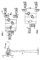
- Fig. 1 is a schematic view of a wind turbine yaw drive and damping system in accordance with the present invention, the system being set for driving the turbine in yaw; and
- Fig. 2 is a view similar to Fig. 1 with the exception that in Fig. 2, the system is set for damping yaw oscillations of the wind turbine when the turbine is oriented in a desired yaw heading.
- Referring to the drawing, a large wind turbine is shown at 10, the wind turbine comprising a pair of
airfoil blades hinge pin 26 to shaft 28. Shaft 28 connects togear box 30 which steps up the rotational speed of the hub and blades to a value equal to the desired speed of rotation of electric generator oralternator 35 connected to the gear box byshaft 37. Anacelle 40 encloses the generator, gear box and connecting shafts. The nacelle includes a yaw bearing 45 which serves to support the nacelle on a tall inherently flexible (elastic), cantileveredtower 50. Wind turbine 10 is of the type wherein the rotor comprising the blades and hub is disposed downwind from the tower and nacelle. The center of mass (c.m.) associated with the rotor, nacelle and other turbine hardware is typically also located downwind from the tower, (longitudinally offset from the vertical axis thereof) the overall weight of the wind turbine excluding the tower thereof being represented byvector 55 extending through the center of mass. - As set forth hereinabove, such a combination of an inherently flexible, cantilevered tower supporting a wind turbine having a center of gravity thereof longitudinally offset from the tower can cause the wind turbine to experience severe yaw ("fishtail") oscillations in response to periodic lateral movement of the upper portion of the tower. To minimize the effects of such yaw oscillations, in accordance with the present invention, a
system 60 is provided, the system including a drive means 65 mounted on the tower and connected to the nacelle for driving the wind turbine in yaw and absorbing energy from the tendency of the turbine to oscillate in yaw for damping such oscillations and minimizing the adverse effects associated therewith. - In the preferred embodiment, drive means 65 comprises a fluid motor including rotors or
movable portions 70 connected to the nacelle at yaw bearing 45 as represented byphantom line 75. Fluid motor 65 may be of any of a number of known varieties whereinrotors 70 are driven by fluid flow thereagainst from a source of pressurizedfluid 80 communicating with drive means 65 throughline first control valve 95 disposed therein, andlines - As illustrated,
control valve 95 has three settings associated therewith, the upper setting (Fig. 2) blocking all flow to drive means 65 and the middle setting (shown in Fig. 1) allowing flow in a clockwise direction fromsource 80 throughlines lines rotor 70 and the connected nacelle in one yaw direction. In the third (lowermost) position flow fromsource 80 is channeled through the drive means in a reverse (counterclockwise) direction throughlines 85,first control valve 95,lines lines line 90 for drivingrotor 70 and the nacelle in the opposite direction. Thus, it is seen that a desired yaw setting may be achieved by selectively controlling the direction of the admission of fluid to drive motor 65 thereby poweringrotor 70 thereof to drive the wind turbine about the yaw axis to the desired yaw heading. When a desired yaw heading has been achieved, the control valve is set to its uppermost position cutting off flow to the motor. -
System 60 also includes aline 110 connected betweenlines control valves line 110 including therein an adjustable orifice orsimilar flow restrictor 125.Flow restrictor 125 aids in controlling the flow through motor 65 by controlling the flow bypassing the motor throughvalves line 110. As shown in the drawings, each ofvalves lines line 110 when drive motor 65 is driving the wind turbine in yaw in response to the admission of fluid to the drive motor fromreservoir 80. The inner settings ofvalves 115 and 120 (Fig. 2) serve to connectlines accumulators - Referring particularly to Fig. 2, when the wind turbine is set in a desired yaw heading,
control valve 95 is set to its uppermost position, cutting off flow fromsource 80 to drive motor 65. Assuming now that the tower is subjected to lateral periodic displacement thereof in the manner set forth hereinabove, such tower displacement will tend to induce yaw oscillations of the nacelle on the tower. The connection ofrotors 70 to the nacelle causes such oscillations to turn the rotors whereupon motor 65 acts as a pump pumping fluid from one accumulator to the other throughcontrol valves source 80 from motor 65. Thus, for example, a tendency of the turbine to oscillate in one direction pumps fluid in a generally counterclockwise direction fromaccumulator 140 through restrictor 130,valve 115, motor 65 (now acting as a pump),valve 120 andrestrictor 135 toaccumulator 145. An oscillation in the opposite direction will cause motor 65 to pump fluid in the opposite direction, fromaccumulator 145 toaccumulator 140. Such pumping as those skilled in the art will appreciate, necessarily effects the dissipation of energy associated with such oscillations thereby damping the oscillations and minimizing the destabilizing effects thereof for maintenance of the wind turbine in the desired yaw heading. It is seen that such energy dissipation (damping) is effected by movement ofrotors 70 against the back pressure of fluid in the lines andaccumulators restrictors 130 and 135 which dissipates substantial amounts of energy as fluid is pumped therethrough by motor 65. In the event that yaw oscillation of severe magnitude come into play,relief valves valve 150 limiting the torsional loading associated with yaw oscillations causing a clockwise pumping of fluid between the accumulators, andvalve 155 limiting the torsional loading due to oscillations associated with a counterclockwise pumping of fluid between the accumulators. - Accordingly, it is seen that yaw drive and
damping system 60 effectively dissipates the energy associated with wind turbine yaw (fishtail) oscillations. This not only maintains the wind turbine at the desired yaw heading but also prevents excitation of tower bending due to rotor imbalances, torque transients, lateral wind gusts, and the lag of rotor teetering behind nacelle translational and yaw motion. Moreover, it is seen that in addition to the hereinabove discussed fishtail oscillations, the present invention serves to damp any dynamic free yaw instability in the wind turbine whether the turbine is operative, or inoperative with the blades parked in feathered positions. Furthermore, in the event of blade or turbine control system damage which would lower the natural frequency of edgewise bending of the blades, the system of the present invention provides a means for damping yaw disturbance due to such reduction in edgewise bending frequency. For the most effective implementation of the present invention, the yaw bearing should be selected for low friction characteristics whereby the system of the present invention will damp yaw oscillations generally throughout the entire period thereof. - While a particular embodiment of the present invention has been shown and described, it will be appreciated by those skilled in the art that various equivalent constructions may be employed without departing from the present invention. Thus, although the yaw drive and damping system has been shown in a fluid mechanical implementation thereof, it is noted that various electromechanical motors, brakes and the like may be employed with equal utility to achieve the desired results and it is intended by the appended claims to cover any such equivalent systems or modifications of the system described herein as fall within the true spirit and scope of this invention.
Claims (9)
Applications Claiming Priority (2)
| Application Number | Priority Date | Filing Date | Title |
|---|---|---|---|
| US06/440,056 US4515525A (en) | 1982-11-08 | 1982-11-08 | Minimization of the effects of yaw oscillations in wind turbines |
| US440056 | 1982-11-08 |
Publications (2)
| Publication Number | Publication Date |
|---|---|
| EP0110807A1 EP0110807A1 (en) | 1984-06-13 |
| EP0110807B1 true EP0110807B1 (en) | 1990-01-03 |
Family
ID=23747240
Family Applications (1)
| Application Number | Title | Priority Date | Filing Date |
|---|---|---|---|
| EP83630181A Expired - Lifetime EP0110807B1 (en) | 1982-11-08 | 1983-11-04 | Minimization of the effects of yaw oscillations in wind turbines |
Country Status (15)
| Country | Link |
|---|---|
| US (1) | US4515525A (en) |
| EP (1) | EP0110807B1 (en) |
| JP (1) | JPS59101586A (en) |
| KR (1) | KR920004724B1 (en) |
| AU (1) | AU562375B2 (en) |
| BR (1) | BR8306077A (en) |
| CA (1) | CA1234542A (en) |
| DE (2) | DE110807T1 (en) |
| DK (1) | DK162359C (en) |
| ES (1) | ES527071A0 (en) |
| FI (1) | FI82853C (en) |
| IL (1) | IL70132A (en) |
| IN (1) | IN159954B (en) |
| NO (1) | NO158639C (en) |
| ZA (1) | ZA838156B (en) |
Families Citing this family (50)
| Publication number | Priority date | Publication date | Assignee | Title |
|---|---|---|---|---|
| FR2590323B1 (en) * | 1985-11-21 | 1989-08-11 | Aerospatiale | BALANCING HUB FOR TWO-BLADE ROTOR |
| US4674954A (en) * | 1986-02-04 | 1987-06-23 | Her Majesty The Queen In Right Of The Province Of Alberta As Represented By The Minister Of Energy And Natural Resources | Wind turbine with damper |
| US4815936A (en) * | 1988-07-05 | 1989-03-28 | United Technologies Corporation | Wind turbine shutdown system |
| US5178518A (en) * | 1990-05-14 | 1993-01-12 | Carter Sr J Warne | Free-yaw, free-pitch wind-driven electric generator apparatus |
| US5354175A (en) * | 1992-03-16 | 1994-10-11 | Northern Power Systems, Inc. | Wind turbine rotor hub and teeter joint |
| SE510110C2 (en) * | 1995-12-18 | 1999-04-19 | Kvaerner Asa | Wind turbine gear system |
| SE506573C2 (en) * | 1996-05-07 | 1998-01-12 | Aegir Konsult Ab | Gear unit for a machinery and wind turbine comprising a gear unit |
| FR2750460B1 (en) * | 1996-07-01 | 2002-01-11 | Vergnet | IMPROVEMENT TO AN AERO-GENERATOR DEVICE |
| US6327957B1 (en) * | 1998-01-09 | 2001-12-11 | Wind Eagle Joint Venture | Wind-driven electric generator apparatus of the downwind type with flexible changeable-pitch blades |
| CA2318386C (en) * | 1998-01-14 | 2008-10-21 | Dancontrol Engineering A/S | Method for measuring and controlling oscillations in a wind turbine |
| DK174404B1 (en) * | 1998-05-29 | 2003-02-17 | Neg Micon As | Wind turbine with vibration damper |
| DK1203155T3 (en) * | 1999-06-16 | 2005-04-11 | Neg Micon As | Attenuation of oscillations in wind turbines |
| DE19930751A1 (en) * | 1999-07-02 | 2001-01-04 | Franz Mitsch | Process for reducing vibrations in wind turbines |
| DE10016912C1 (en) * | 2000-04-05 | 2001-12-13 | Aerodyn Eng Gmbh | Operation of offshore wind turbines dependent on the natural frequency of the tower |
| US6682302B2 (en) | 2001-03-20 | 2004-01-27 | James D. Noble | Turbine apparatus and method |
| JP3978186B2 (en) * | 2001-12-28 | 2007-09-19 | 三菱重工業株式会社 | Upwind type windmill and driving method thereof |
| GB0218401D0 (en) * | 2002-08-08 | 2002-09-18 | Hansen Transmissions Int | Wind turbine gear unit |
| NO20041208L (en) * | 2004-03-22 | 2005-09-23 | Sway As | Procedure for reducing axial power variations for rotor and directional control for wind power with active pitch control |
| US7238009B2 (en) * | 2004-05-06 | 2007-07-03 | Grand Vent Power, Llc | Offshore windmill electric generators |
| US7309930B2 (en) * | 2004-09-30 | 2007-12-18 | General Electric Company | Vibration damping system and method for variable speed wind turbines |
| CN100459834C (en) * | 2005-02-01 | 2009-02-04 | 富士康(昆山)电脑接插件有限公司 | Electric connector |
| CN101351606A (en) * | 2005-05-13 | 2009-01-21 | 特雷西·利文斯顿 | Structural tower |
| NO325856B1 (en) * | 2005-11-01 | 2008-08-04 | Hywind As | Method for damping unstable free rigid body oscillations in a floating wind turbine installation |
| US20070114799A1 (en) * | 2005-11-18 | 2007-05-24 | Andre Riesberg | Systems and methods for damping a displacement of a wind turbine tower |
| CN101432216B (en) | 2005-12-30 | 2012-08-29 | 通用风能有限责任公司 | Lifting system and apparatus for constructing wind turbine towers |
| US7528497B2 (en) * | 2006-07-11 | 2009-05-05 | Hamilton Sundstrand Corporation | Wind-turbine with load-carrying skin |
| WO2008042410A2 (en) * | 2006-10-02 | 2008-04-10 | Wind Tower Systems, Llc | Drive pin system for a wind turbine structural tower |
| US8069634B2 (en) * | 2006-10-02 | 2011-12-06 | General Electric Company | Lifting system and apparatus for constructing and enclosing wind turbine towers |
| US20080080946A1 (en) * | 2006-10-02 | 2008-04-03 | Tracy Livingston | Expansion pin system for a wind turbine structural tower |
| EP2232063B1 (en) * | 2007-11-30 | 2017-09-27 | Vestas Wind Systems A/S | A wind turbine, a method for controlling a wind turbine and use thereof |
| US8362632B2 (en) * | 2007-11-30 | 2013-01-29 | Vestas Wind Systems A/S | Wind turbine, a method for controlling a wind turbine and use thereof |
| US20090148289A1 (en) * | 2007-12-06 | 2009-06-11 | Thomas Edenfeld | Active damper against generator base frame vibrations |
| US8016268B2 (en) * | 2008-05-30 | 2011-09-13 | Wind Tower Systems, Llc | Wind tower service lift |
| EP2189656A3 (en) * | 2008-11-20 | 2013-04-03 | Vestas Wind Systems A/S | Wind turbine yawing system |
| US8021101B2 (en) * | 2008-12-15 | 2011-09-20 | General Electric Company | Wind turbine and method of assembling the same |
| CA2746880A1 (en) * | 2008-12-15 | 2010-07-01 | Wind Tower Systems, Llc | Structural shape for wind tower members |
| US7944070B2 (en) * | 2009-08-25 | 2011-05-17 | Vestas Wind Systems A/S | Yaw system for a nacelle of a wind turbine and wind turbine |
| US20110175365A1 (en) * | 2010-01-15 | 2011-07-21 | Douglas Hines | Wind-driven electric generator structure vibration-deadening apparatus and methods |
| US8203230B2 (en) * | 2010-06-29 | 2012-06-19 | General Electric Company | Yaw bearing system |
| EP2402597B1 (en) * | 2010-06-29 | 2016-08-03 | Siemens Aktiengesellschaft | Wind turbine yaw system and method of controlling the same |
| US8178989B2 (en) * | 2010-12-15 | 2012-05-15 | General Electric Company | System and methods for adjusting a yaw angle of a wind turbine |
| ES2596253T3 (en) * | 2011-11-24 | 2017-01-05 | Vestas Wind Systems A/S | A yaw system comprising a preload mechanism |
| US20130164134A1 (en) * | 2011-12-23 | 2013-06-27 | Leonid Goldstein | Limited Yaw Wind Turbine |
| CN102635506A (en) * | 2012-04-24 | 2012-08-15 | 广东明阳风电产业集团有限公司 | Hydraulic lubrication cooling comprehensive control device of wind generation set |
| DE102012110466A1 (en) * | 2012-10-31 | 2014-04-30 | 2-B Energy B.V. | Method for operating a wind turbine, wind turbine and control device for a wind turbine |
| DE102013101012A1 (en) * | 2013-02-01 | 2014-08-07 | 2-B Energy Holding B.V. | Control device for a yaw system of a wind turbine |
| US9366224B2 (en) * | 2013-06-27 | 2016-06-14 | General Electric Company | Wind turbine blade and method of fabricating the same |
| EP2821636B1 (en) * | 2013-07-03 | 2017-09-06 | Alstom Renovables España, S.L. | Method of operating a wind turbine |
| DE102015000787A1 (en) * | 2015-01-26 | 2016-07-28 | Senvion Gmbh | Load-receiving means for a tower or a tower section of a wind turbine and method for erecting a wind turbine |
| WO2017009943A1 (en) * | 2015-07-14 | 2017-01-19 | 株式会社日立製作所 | Downwind-type wind power generation system and method for controlling downwind-type wind power generation system |
Citations (1)
| Publication number | Priority date | Publication date | Assignee | Title |
|---|---|---|---|---|
| US4353681A (en) * | 1980-05-19 | 1982-10-12 | United Technologies Corporation | Wind turbine with yaw trimming |
Family Cites Families (19)
| Publication number | Priority date | Publication date | Assignee | Title |
|---|---|---|---|---|
| US2360791A (en) * | 1941-03-22 | 1944-10-17 | Morgan Smith S Co | Wind turbine |
| CH242424A (en) * | 1943-02-04 | 1946-05-15 | Porsche Kg | Wind power machine. |
| US2517135A (en) * | 1947-08-15 | 1950-08-01 | Wesley H Rudisill | Electric generating system |
| US2784556A (en) * | 1954-03-01 | 1957-03-12 | Havilland Propellers Ltd De | Anemo-electric power plants |
| CH395693A (en) * | 1962-12-19 | 1965-07-15 | Rerat Charles | Auxiliary device with movable stop for a machine tool |
| US4008006A (en) * | 1975-04-24 | 1977-02-15 | Bea Karl J | Wind powered fluid compressor |
| DE2655026C2 (en) * | 1976-12-04 | 1979-01-18 | Ulrich Prof. Dr.-Ing. 7312 Kirchheim Huetter | Wind energy converter |
| FR2375649A1 (en) * | 1976-12-27 | 1978-07-21 | Aerowatt | Directional orientation system for wind driven generator - has torque applied proportional to orientation speed to oppose movement direction |
| US4160170A (en) * | 1978-06-15 | 1979-07-03 | United Technologies Corporation | Wind turbine generator pitch control system |
| SE413048B (en) * | 1979-03-27 | 1980-03-31 | Pettersson Bertil | VIEWED AT A MAJOR HORIZONTAL AXLED VIDTURBIN WITH FLAPPING NAV REGULATED FLAPPING GRANGE |
| US4366387A (en) * | 1979-05-10 | 1982-12-28 | Carter Wind Power | Wind-driven generator apparatus and method of making blade supports _therefor |
| US4297076A (en) * | 1979-06-08 | 1981-10-27 | Lockheed Corporation | Wind turbine |
| US4298313A (en) * | 1979-06-18 | 1981-11-03 | Hohenemser Kurt H | Horizontal axis wind generator having adaptive cyclic pitch control |
| DE3008379C2 (en) * | 1980-03-05 | 1982-02-18 | Voith Getriebe Kg, 7920 Heidenheim | Device for positioning the rotor head of a wind turbine |
| US4329117A (en) * | 1980-04-22 | 1982-05-11 | United Technologies Corporation | Wind turbine with drive train disturbance isolation |
| US4366386A (en) * | 1981-05-11 | 1982-12-28 | Hanson Thomas F | Magnus air turbine system |
| US4408954A (en) * | 1981-07-27 | 1983-10-11 | Earle John L | Windmill yaw and speed controls |
| US4420692A (en) * | 1982-04-02 | 1983-12-13 | United Technologies Corporation | Motion responsive wind turbine tower damping |
| US4435647A (en) * | 1982-04-02 | 1984-03-06 | United Technologies Corporation | Predicted motion wind turbine tower damping |
-
1982
- 1982-11-08 US US06/440,056 patent/US4515525A/en not_active Expired - Fee Related
-
1983
- 1983-10-26 CA CA000439705A patent/CA1234542A/en not_active Expired
- 1983-11-01 ZA ZA838156A patent/ZA838156B/en unknown
- 1983-11-02 NO NO833992A patent/NO158639C/en unknown
- 1983-11-04 AU AU20998/83A patent/AU562375B2/en not_active Ceased
- 1983-11-04 IL IL70132A patent/IL70132A/en not_active IP Right Cessation
- 1983-11-04 BR BR8306077A patent/BR8306077A/en not_active IP Right Cessation
- 1983-11-04 EP EP83630181A patent/EP0110807B1/en not_active Expired - Lifetime
- 1983-11-04 DE DE198383630181T patent/DE110807T1/en active Pending
- 1983-11-04 DE DE8383630181T patent/DE3381051D1/en not_active Expired - Fee Related
- 1983-11-05 IN IN1364/CAL/83A patent/IN159954B/en unknown
- 1983-11-07 DK DK508383A patent/DK162359C/en not_active IP Right Cessation
- 1983-11-07 FI FI834073A patent/FI82853C/en not_active IP Right Cessation
- 1983-11-07 ES ES527071A patent/ES527071A0/en active Granted
- 1983-11-08 JP JP58209762A patent/JPS59101586A/en active Granted
- 1983-11-08 KR KR1019830005285A patent/KR920004724B1/en not_active IP Right Cessation
Patent Citations (1)
| Publication number | Priority date | Publication date | Assignee | Title |
|---|---|---|---|---|
| US4353681A (en) * | 1980-05-19 | 1982-10-12 | United Technologies Corporation | Wind turbine with yaw trimming |
Also Published As
| Publication number | Publication date |
|---|---|
| CA1234542A (en) | 1988-03-29 |
| JPS59101586A (en) | 1984-06-12 |
| FI82853B (en) | 1991-01-15 |
| BR8306077A (en) | 1984-06-12 |
| NO833992L (en) | 1984-05-09 |
| ES8407556A1 (en) | 1984-10-01 |
| DE3381051D1 (en) | 1990-02-08 |
| IL70132A0 (en) | 1984-02-29 |
| KR920004724B1 (en) | 1992-06-15 |
| EP0110807A1 (en) | 1984-06-13 |
| NO158639B (en) | 1988-07-04 |
| NO158639C (en) | 1988-10-12 |
| FI834073A0 (en) | 1983-11-07 |
| DK162359C (en) | 1992-03-09 |
| US4515525A (en) | 1985-05-07 |
| KR840007144A (en) | 1984-12-05 |
| AU562375B2 (en) | 1987-06-11 |
| FI82853C (en) | 1991-04-25 |
| AU2099883A (en) | 1984-05-17 |
| JPH0448939B2 (en) | 1992-08-10 |
| DE110807T1 (en) | 1984-10-11 |
| FI834073A (en) | 1984-05-09 |
| ES527071A0 (en) | 1984-10-01 |
| DK162359B (en) | 1991-10-14 |
| DK508383A (en) | 1984-05-09 |
| DK508383D0 (en) | 1983-11-07 |
| ZA838156B (en) | 1984-06-27 |
| IL70132A (en) | 1988-07-31 |
| IN159954B (en) | 1987-06-13 |
Similar Documents
| Publication | Publication Date | Title |
|---|---|---|
| EP0110807B1 (en) | Minimization of the effects of yaw oscillations in wind turbines | |
| EP0350425B1 (en) | Wind turbine shutdown system | |
| JP5704464B2 (en) | Wind turbine with compensated motor torque | |
| EP1828598B1 (en) | Vertical axis turbine | |
| EP0530315B1 (en) | Free-yaw, free-pitch wind-driven electric generator apparatus | |
| US4710100A (en) | Wind machine | |
| US4533297A (en) | Rotor system for horizontal axis wind turbines | |
| FI79387C (en) | Wind turbine with rotor blade with variable blade angle | |
| EP0087471A1 (en) | Wind energy conversion system | |
| CA1284621C (en) | Wind turbine system using a vertical axis savonius-type rotor | |
| US20070132247A1 (en) | Electric power generation system | |
| EA013064B1 (en) | A turbine driven electric power production system and a method for control thereof | |
| JPS63192969A (en) | Pitch control hub for wind-force turbine | |
| US4439108A (en) | Windmill having centrifically feathered rotors to control rotor speed | |
| US4439105A (en) | Offset-axis windmill having inclined power shaft | |
| US11434869B2 (en) | Vertical wind turbine with controlled tip-speed ratio behavior, kit for same, and method for operating same | |
| WO2017009943A1 (en) | Downwind-type wind power generation system and method for controlling downwind-type wind power generation system | |
| KR100541231B1 (en) | High efficiency vertical type wind-power plant | |
| WO2011039777A2 (en) | System for controlling cone and pitch angle of a rotor blade assembly of a wind turbine | |
| GB2076070A (en) | Wind turbine | |
| KR20130059319A (en) | Tidal power plant and method for operating said tidal power plant | |
| CA1292949C (en) | Wind turbine shutdown system | |
| JP2022045298A (en) | Wind power generator | |
| RU2193688C1 (en) | Windmill-electric set | |
| CZ280607B6 (en) | Wind engine |
Legal Events
| Date | Code | Title | Description |
|---|---|---|---|
| PUAI | Public reference made under article 153(3) epc to a published international application that has entered the european phase |
Free format text: ORIGINAL CODE: 0009012 |
|
| AK | Designated contracting states |
Designated state(s): DE FR GB IT NL SE |
|
| ITCL | It: translation for ep claims filed |
Representative=s name: RICCARDI SERGIO & CO. |
|
| TCNL | Nl: translation of patent claims filed | ||
| EL | Fr: translation of claims filed | ||
| DET | De: translation of patent claims | ||
| 17P | Request for examination filed |
Effective date: 19840803 |
|
| GRAA | (expected) grant |
Free format text: ORIGINAL CODE: 0009210 |
|
| AK | Designated contracting states |
Kind code of ref document: B1 Designated state(s): DE FR GB IT NL SE |
|
| ET | Fr: translation filed | ||
| REF | Corresponds to: |
Ref document number: 3381051 Country of ref document: DE Date of ref document: 19900208 |
|
| ITF | It: translation for a ep patent filed |
Owner name: UFFICIO BREVETTI RICCARDI & C. |
|
| PLBE | No opposition filed within time limit |
Free format text: ORIGINAL CODE: 0009261 |
|
| STAA | Information on the status of an ep patent application or granted ep patent |
Free format text: STATUS: NO OPPOSITION FILED WITHIN TIME LIMIT |
|
| 26N | No opposition filed | ||
| ITTA | It: last paid annual fee | ||
| PGFP | Annual fee paid to national office [announced via postgrant information from national office to epo] |
Ref country code: FR Payment date: 19931011 Year of fee payment: 11 |
|
| PGFP | Annual fee paid to national office [announced via postgrant information from national office to epo] |
Ref country code: DE Payment date: 19931020 Year of fee payment: 11 |
|
| PGFP | Annual fee paid to national office [announced via postgrant information from national office to epo] |
Ref country code: SE Payment date: 19941014 Year of fee payment: 12 Ref country code: GB Payment date: 19941014 Year of fee payment: 12 |
|
| PGFP | Annual fee paid to national office [announced via postgrant information from national office to epo] |
Ref country code: NL Payment date: 19941130 Year of fee payment: 12 |
|
| EAL | Se: european patent in force in sweden |
Ref document number: 83630181.2 |
|
| PG25 | Lapsed in a contracting state [announced via postgrant information from national office to epo] |
Ref country code: FR Effective date: 19950731 |
|
| PG25 | Lapsed in a contracting state [announced via postgrant information from national office to epo] |
Ref country code: DE Effective date: 19950801 |
|
| REG | Reference to a national code |
Ref country code: FR Ref legal event code: ST |
|
| PG25 | Lapsed in a contracting state [announced via postgrant information from national office to epo] |
Ref country code: GB Effective date: 19951104 |
|
| PG25 | Lapsed in a contracting state [announced via postgrant information from national office to epo] |
Ref country code: SE Effective date: 19951105 |
|
| PG25 | Lapsed in a contracting state [announced via postgrant information from national office to epo] |
Ref country code: NL Effective date: 19960601 |
|
| GBPC | Gb: european patent ceased through non-payment of renewal fee |
Effective date: 19951104 |
|
| NLV4 | Nl: lapsed or anulled due to non-payment of the annual fee |
Effective date: 19960601 |
|
| EUG | Se: european patent has lapsed |
Ref document number: 83630181.2 |