EP0109413B1 - Machine d'enroulement helicoidal de conduites - Google Patents
Machine d'enroulement helicoidal de conduites Download PDFInfo
- Publication number
- EP0109413B1 EP0109413B1 EP83901567A EP83901567A EP0109413B1 EP 0109413 B1 EP0109413 B1 EP 0109413B1 EP 83901567 A EP83901567 A EP 83901567A EP 83901567 A EP83901567 A EP 83901567A EP 0109413 B1 EP0109413 B1 EP 0109413B1
- Authority
- EP
- European Patent Office
- Prior art keywords
- rollers
- strip
- roller
- annulus
- joining
- Prior art date
- Legal status (The legal status is an assumption and is not a legal conclusion. Google has not performed a legal analysis and makes no representation as to the accuracy of the status listed.)
- Expired
Links
Images


Classifications
-
- B—PERFORMING OPERATIONS; TRANSPORTING
- B21—MECHANICAL METAL-WORKING WITHOUT ESSENTIALLY REMOVING MATERIAL; PUNCHING METAL
- B21C—MANUFACTURE OF METAL SHEETS, WIRE, RODS, TUBES OR PROFILES, OTHERWISE THAN BY ROLLING; AUXILIARY OPERATIONS USED IN CONNECTION WITH METAL-WORKING WITHOUT ESSENTIALLY REMOVING MATERIAL
- B21C37/00—Manufacture of metal sheets, bars, wire, tubes or like semi-manufactured products, not otherwise provided for; Manufacture of tubes of special shape
- B21C37/06—Manufacture of metal sheets, bars, wire, tubes or like semi-manufactured products, not otherwise provided for; Manufacture of tubes of special shape of tubes or metal hoses; Combined procedures for making tubes, e.g. for making multi-wall tubes
- B21C37/12—Making tubes or metal hoses with helically arranged seams
- B21C37/128—Control or regulating devices
-
- B—PERFORMING OPERATIONS; TRANSPORTING
- B21—MECHANICAL METAL-WORKING WITHOUT ESSENTIALLY REMOVING MATERIAL; PUNCHING METAL
- B21C—MANUFACTURE OF METAL SHEETS, WIRE, RODS, TUBES OR PROFILES, OTHERWISE THAN BY ROLLING; AUXILIARY OPERATIONS USED IN CONNECTION WITH METAL-WORKING WITHOUT ESSENTIALLY REMOVING MATERIAL
- B21C37/00—Manufacture of metal sheets, bars, wire, tubes or like semi-manufactured products, not otherwise provided for; Manufacture of tubes of special shape
- B21C37/06—Manufacture of metal sheets, bars, wire, tubes or like semi-manufactured products, not otherwise provided for; Manufacture of tubes of special shape of tubes or metal hoses; Combined procedures for making tubes, e.g. for making multi-wall tubes
- B21C37/12—Making tubes or metal hoses with helically arranged seams
-
- B—PERFORMING OPERATIONS; TRANSPORTING
- B29—WORKING OF PLASTICS; WORKING OF SUBSTANCES IN A PLASTIC STATE IN GENERAL
- B29C—SHAPING OR JOINING OF PLASTICS; SHAPING OF MATERIAL IN A PLASTIC STATE, NOT OTHERWISE PROVIDED FOR; AFTER-TREATMENT OF THE SHAPED PRODUCTS, e.g. REPAIRING
- B29C53/00—Shaping by bending, folding, twisting, straightening or flattening; Apparatus therefor
- B29C53/56—Winding and joining, e.g. winding spirally
- B29C53/58—Winding and joining, e.g. winding spirally helically
- B29C53/72—Winding and joining, e.g. winding spirally helically using external forming surfaces
-
- B—PERFORMING OPERATIONS; TRANSPORTING
- B29—WORKING OF PLASTICS; WORKING OF SUBSTANCES IN A PLASTIC STATE IN GENERAL
- B29C—SHAPING OR JOINING OF PLASTICS; SHAPING OF MATERIAL IN A PLASTIC STATE, NOT OTHERWISE PROVIDED FOR; AFTER-TREATMENT OF THE SHAPED PRODUCTS, e.g. REPAIRING
- B29C53/00—Shaping by bending, folding, twisting, straightening or flattening; Apparatus therefor
- B29C53/80—Component parts, details or accessories; Auxiliary operations
- B29C53/82—Cores or mandrels
- B29C53/821—Mandrels especially adapted for winding and joining
- B29C53/825—Mandrels especially adapted for winding and joining for continuous winding
- B29C53/827—Mandrels especially adapted for winding and joining for continuous winding formed by several elements rotating about their own axes
Definitions
- This invention relates to an improved helically wound pipe winding machine and in particular it relates to a machine of the type in which a strip of any specific configuration is helically wound so that the edges of the strip overlap and lock together to form a pipe.
- a strip which has a flat body section from which extend outwardly projecting ribs running longitudinally on the strip and spaced apart one from another to provide reinforcement to the body of the strip.
- a projecting locking member which is shaped so that it can engage in an appropriately shaped socket at the other edge of the strip when the strip is being helically wound to form a pipe, and various shapes of joining members are known which may be reinforced with added flaps or extensions on at least one of the edges of the strip.
- the machine for winding such a strip may take various forms but according to one form disclosed in European Patent Specification No. 0011916 (corresponding to AU-B-51622179), a series of rollers are positioned annularly about a longitudinal axis on which the tube is being formed and the strip is forcibly fed into a helical formation by being driven around under guidance of the rollers of the annulus which define the diameter of the finished pipe.
- the helical curvature of the strip is achieved by using special joining rollers such for instance as where the part which engages the strip and the overlapping portion has two diameters so that, when the two overlapping edges of the strip are forced together to provide the interlock, the strip being fed, and the pipe being formed, have differential pressures applied to them so that the join is made under such differential pressure.
- the differential pressure is also used to give a required curvature to the strip to form a tube of a selected diameter, and various prior art literature refers to different methods of using such pressures to form a helical convolution at the joining rollers of the strip.
- Such mechanisms also require to be able to readily produce pipes of varying diameters and in some cases to vary the diameter during formation to produce tapered configuration but the present invention relates particularly to the production of pipes of selected sizes by a simple mechanism which uses a feed, roller or rollers to move the strip into the mechanism and then guides the strip into a helical convolution to cause one edge of the strip to engage the lock to the other edge of the strip as the pipe is produced.
- One of the problems which exists with this type of apparatus is to be able not only to vary the diameter of the pipe being formed but to arrange the helical angle to allow correct relationship between the width of the strip and the diameter of the pipe and it is an object of the present invention to provide certain improvements to the mechanism to achieve this.
- the invention provides a machine for forming helically wound pipes from a strip in which a series of rollers form an annulus of rollers arranged to curve the strip to a helical form within the annulus with the edges of the strip overlap-.
- ping comprising a joining roller and a pressure member positioned at the meeting of the first convolution with the strip to press the end of the convolution into locking engagement with the strip, a pair of feed rollers remote from the joining roller at a defined distant position therefrom to control the rate and direction of feed of the strip to the joining roller and driving means for the joining roller and for at least one of the feed rollers to maintain the strip between the joining rollers and the feed rollers in tension, characterised in that the rollers are supported by a pair of rings which are spaced apart in a frame and are relatively angularly adjustable and a strip guide engages the shaft of the joining roller to extend normally therefrom to guide the strip to the joining and pressure rollers, whereby the angular position of the rollers and the angle of the strip guide are variable
- the machine comprises a pair of circular rings 1, which are spaced apart and which each carry a series of rollers 2 and 3 extending generally in the direction of the axis 4 of the pipe 5 being formed, and these rollers 2 and 3 are mounted on rods 6 which have longitudinal racks 7 on them engaged by pinions 8A on bearing means on the rings 1 so that by rotating the shafts 9 and thus the pinions the position of the rollers 2, 3 radially can be adjusted.
- the shaft 9 and pinions are arranged in two pairs around the periphery of the frames 1 and are driven by chains 10 and 11 respectively on each side of sprockets 8 on the shafts 9 so that alternate rollers 2 and 3 can be independently moved, the reason for this being to allow some rollers to remain in an outer position when forming a small pipe but allowing the other rollers to be projected into operating position, allowing closer spacing between those rollers in use at the time.
- Each rod 6 can have either the single roller 2 as shown or twin rollers 3.
- the chain 10 moves the one set of rollers 3 radially while the other chain 11 moves the interposed rollers 2 radially.
- the drives for the chains may be interconnected between the two sides of the machine so that a single control can be used to move all of the rollers simultaneously if it is required to maintain synchronism.
- the rings 1-1 are supported on a main frame 12 to be coaxial but can be orientated independently by a mounting as shown in Fig. 10.
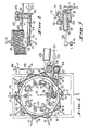
- the mechanism which feeds the strip 15 to the annulus formed by the rollers 2 and 3 comprises a pair of drive rollers 16 and 17 remote from where the join is being made, and a pair of joining rollers 18 and 19 where the strip is pressed together to form a junction between the strip 15 and the first convolution 20 of the pipe 5.
- the feed rollers 16 and 17 at the first position engage both sides of the strip 15 to form driving means for the strip but the joining rollers 18 and 19 are so positioned that the roller 18 engages the strip and the convolutions forming the pipe but the other roller 19 engages the join 21 and extends from this position in the direction of the formed pipe so that roller 18 supports the pipe 5 being formed but the roller 19 presses the join 21 together but extends to drive the first convolution 20 to serve as means for rotating the tube 5 as it is formed.
- roller 18 is driven by a chain 23 from the roller 17.
- the drive for the rollers 16 and 17 and the rollers 18 and 19 is derived from a motor 25 rotating a worm wheel assembly 26 in a gearbox 27, while the roller 17 is driven from the shaft of the roller 16 through a pair of gear rollers 28 and 29, the gearing and size of the rollers ensuring the same peripheral speed of the rollers 16 and 17.
- the roller 18 is driven from the shaft of the roller 17 by the chain 23, and the diameters of the roller 18 and the chain sprockets 30 and 31, which are fixed on ths shafts of the rollers 17 and 18, are so selected that the peripheral speed of the joining roller 18 is slightly higher than the peripheral speed of the feed rollers 16 and 17 so that the part of the strip between the feed rollers 16 and 17 and the joining rollers 18 and 19 is under tension.
- a guide 33 for the strip allows the strip to be fed from a roll to engage the drive rollers 16 and 17 with the strip itself in a horizontal position and by driving this pair of rollers 16 and 17 at a speed different to the second pair of rollers 18 and 19 any required stress can be produced at the joining area by tensioning the strip between the joining rollers 18, 19 and the feed rollers 16, 17, and this stress assists in forming the strip to its helical interlocking configuration so that it is possible to provide the necessary differential stress at the joining area and also control the curvature of the strip into a helical form to move circularly around within the annulus of rollers 2 and 3 which ensure final determination of the diameter of the pipe being formed and give close control.
- the above referred to tension may be maintained by variation in the size of the rollers or the rate of revolution thereof.
- Fig. 2 shows the need to align the strip 15 with the angle of the helix so that the strip guide 33 is at an angle to the axis of the pipe being formed.
- the strip guide 33 pivots about the shaft 34 which carries the roller 18 so that as the roller 18 is adjusted simultaneously with the rollers 2 the correct feed of the strip 15 into the annulus takes place, the guide 33 carrying the rollers 16 and 17 and gearbox 27 and motor 25 being suspended toward its free end by a threaded rod 35 having axial adjustment means 36 engaging a bracket 37 on the main support frame 12 which also supports the rings 1.
- the rings 1 are adjustable about the axes on the support frame 12 by means such as shown in the embodiment shown in Fig. 10.
- the roller 19 rotates on an arm 38 carried by the guide 33, the arm having a loading screw 39 engaging it to allow selection of the pressure the joining roller 19 exerts on the strip as the strip moves forward under the drive exerted by the roller 18.
- rollers 2 and 3 which comprise the roller cage are also driven and rotated about their axes and this form will be described herein with reference to Fig. 4 to 9, as the second embodiment.
- each of these trolleys can comprise a pair of frames so arranged that the position of carry rollers supported by the frames can be varied in relation to the axial position of the pipe being formed so that when the pipe lies on these carry rollers they form a continuation as it were in the same plane as the guide rollers 2 and 3 which are carried by the rings 1.
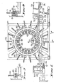
- a pair of rings 45 carry rods 46, in this case, threaded which are axially confined but adjustable by nuts 47 and 48 and carry rollers 49 by means of self-aligning bearings 50, the rings 45 being supported by a frame 51 but adjustable thereon about the pipe axis by means as shown in Fig. 10.
- the strip guide 54 engages the shaft of the roller 49A at the joining roller locality which in this case is similar to the remaining rollers 49 which form the annulus, the free end of the strip guide 54 being supported by a link 55 joining it to the frame 51, this allowing adjustment of the roller 49A simultaneously with the remaining rollers 49 while maintaining correct feed of the strip into the annulus.
- the roller 56 is mounted on an arm 57 pivoted to a bracket 58 connected to 41 a shaft for the roller 49A, and the arm has a loading screw 59.
- roller 49B adjacent to the roller 49A is shortened and its shaft shaped to allow the guide 54 to project past it.
- all rollers 49, 49A and 49B are driven by a belt 62 which encircles the rollers of the annulus and passes around a driving pulley 63 and a take-up drum 64, the drum 64 being rotationally mounted on a support 65 slidably carried on guide rods 66 projecting from the frame 51 and engaged by an axially confined threaded adjustment rod 67 which is rotated by a hand wheel 68, whereby the drum 64 can be positioned to maintain belt tension around the annulus of rollers 49 and the driving pulley 63.
- the pulley 63 is driven from a motor 70 through a gearbox 71 which also drives the two feed rollers 72 and 73 which engage the strip 74 and control the rate of feed to the joining rollers, in this case the roller 49A and the pressure roller 56.
- the pipe is driven by each of the rollers 49, 49A and 49B to give an accurate constant drive, this drive being slightly faster than the feed by the feed rollers 72 and 73 so that the strip is maintained in tension between the feed rollers 72 and 73 and the joining rollers 49A and 56.
- the hand-operated adjustment 67-68 could be replaced by spring or fluid pressure operated means moving the support 65 to automatically maintain the driving tension on the belt 62.
- Fig. 13 of course has the ring 77A located at the join, but as shown in Fig. 7 the rings 77 can be positioned at any part of the strip 74 so long as they engage between a pair of the ribs 79, when the strip is provided with ribs, the rings however being progressively further along the sequentially arranged rollers 49 to cause particularly the first convolution of the strip to follow an accurate helical path to cause the locking projection 81 to correctly engage in the groove in the rib 80 at the end of the first convolution.
- a simultaneous adjustment of all rods 41 can be effected by means similar to Fig. 1 and as detailed in Fig. 6, the embodiment of Fig. 5 can be used in which a sprocket 85 is captively mounted in a split ring 45A and is threaded to engage the screw thread on the rod 41.
- the rods of each embodiment may be plain, thus the rods 6 or 46 or 93 can pass through apertures in the rings 1,45 or 87 and the rings can have clamping means such as cams to lock the rods.
- clamping means such as cams to lock the rods.
- Figs. 10 and 11 show how this can be achieved, the embodiment showing the general assembly of rollers 49 of Fig. 4 and the strip drive of Fig. 1, but the rings 87 are each formed in two parts 87A and 87B, connected together by a hinge 88 and having detent means 89 to lock the rings together.
- the frame 50 has slotted ends 91 through which bolts 92 pass to lock the rings 87 to the frame 90 but allowing adjustment about the pipe axis to slope the rollers to suit the helix of the pipe, depending on the width of the strip and the diameter of the pipe being formed.
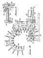
- the threaded rods are designated 93, the feed rollers 94 and 95 being driven from the motor 96, the chain 97 driving the roller 98 at the joining locality while the roller 99 is the pressure roller to press the strip 100 onto the joining roller 98.
- the strip guide 101 is again pivoted on the axis of the shaft 102 of the roller 98 carried by the rod 93A, while the free end of the strip guide 101 is suspended by a rod 103 with adjustment means 104.
- the threaded rods 93 and 93A are controlled axially by nuts 105 captive on the rings 87.
- the roller 99 is carried on a bracket 106 projecting from the strip guide 101 and has loading means in the form of a threaded rod 107.
- the roller of the annulus are designated 108.
- Fig. 14 shows how a joining roller 110 may be used when the strip 111 is inverted to have the ribs 112 inwardly projecting in a pipe, the driven joining roller 113 being plain but the joining roller having a main pressure face 114 and a ring 115 to press the flap 116 into position, the effect being similar to that described with reference to Fig. 13.
- the rollers 2, 3 or 49 can comprise a series of segments 121 which can adjust independently to variation in peripheral speed at selected localities of the helix, and are self-aligning with the direction of the force which is being exerted by the annulus rollers.
- rollers 121 which extend along the line of the original rollers, but these rollers 121 maybe mounted to caster as shown so that they can take the direction of the force exerted.
- the contacting members instead of having to very carfully align the annulus rollers the contacting members now align themselves according to the force at the particular locality.
- a bar 122 carries the rollers 121 by means of forks 123 having spindles 124 engaging the bar 122.
- Fig. 17 is shown one end of a roller 130 supported by a self-aligning bearing 131 on a rod 132, showing how the roller could be driven by flexible drive cables 133 engaging the spindles 134 of the rollers.
- a series of such cables could be synchronously driven from a gearbox with the required drive outlets.
- This assembly can be applied for instance in the form of Fig. 4 as it allows the diameter of the annulus to be varied.
- the rod 132 is plane and is locked in position by a cam 135 on a lever 136 pivoted at 137 to the ring 138 which corresponds to the rings 1, 45 and 87.
- a roller 19, 56 or 99 is shown as the pressure member to press the strip onto the joining roller 18, 49A or 98, this can be replaced by a flat member, this being particularly applicable in Fig. 10 where the pipe is formed over another pipe.
Abstract
Claims (11)
Priority Applications (1)
| Application Number | Priority Date | Filing Date | Title |
|---|---|---|---|
| AT83901567T ATE38481T1 (de) | 1982-05-27 | 1983-05-20 | Schraubenfoermige rohraufwindevorrichtung. |
Applications Claiming Priority (2)
| Application Number | Priority Date | Filing Date | Title |
|---|---|---|---|
| AU4172/82 | 1982-05-27 | ||
| AUPF417282 | 1982-05-27 |
Publications (3)
| Publication Number | Publication Date |
|---|---|
| EP0109413A1 EP0109413A1 (fr) | 1984-05-30 |
| EP0109413A4 EP0109413A4 (fr) | 1985-12-11 |
| EP0109413B1 true EP0109413B1 (fr) | 1988-11-09 |
Family
ID=3769554
Family Applications (1)
| Application Number | Title | Priority Date | Filing Date |
|---|---|---|---|
| EP83901567A Expired EP0109413B1 (fr) | 1982-05-27 | 1983-05-20 | Machine d'enroulement helicoidal de conduites |
Country Status (8)
| Country | Link |
|---|---|
| US (1) | US4616495A (fr) |
| EP (1) | EP0109413B1 (fr) |
| DE (1) | DE3378404D1 (fr) |
| DK (1) | DK159869C (fr) |
| EG (1) | EG16466A (fr) |
| FI (1) | FI85230C (fr) |
| PH (1) | PH21620A (fr) |
| WO (1) | WO1983004196A1 (fr) |
Cited By (3)
| Publication number | Priority date | Publication date | Assignee | Title |
|---|---|---|---|---|
| DE102009043932A1 (de) * | 2009-09-02 | 2011-03-10 | Stükerjürgen, Ferdinand | Wickelrohr mit erhöhter Stabilität |
| DE102013100719A1 (de) * | 2013-01-24 | 2014-07-24 | Stefan Kukutschka | Kunststoff-Verbundrohre mit Verfahren und Vorrichtung zur kontinuierlichen Herstellung |
| RU2571134C2 (ru) * | 2010-09-27 | 2015-12-20 | МББ Фертигуннгстехник ГмбХ | Укладочная машина и способ изготовления изделия из композитного материала |
Families Citing this family (19)
| Publication number | Priority date | Publication date | Assignee | Title |
|---|---|---|---|---|
| IN167882B (fr) * | 1986-03-19 | 1991-01-05 | Rib Loc Aust Pty Ltd | |
| JPH0729368B2 (ja) * | 1986-08-27 | 1995-04-05 | 積水化学工業株式会社 | 製管機 |
| JPH0811419B2 (ja) * | 1986-09-11 | 1996-02-07 | 積水化学工業株式会社 | 製管機 |
| CH671922A5 (fr) * | 1987-04-14 | 1989-10-13 | Ametex Ag | |
| JPH0737064B2 (ja) * | 1987-12-14 | 1995-04-26 | 積水化学工業株式会社 | 製管機 |
| CH677741A5 (fr) * | 1989-01-05 | 1991-06-28 | Ametex Ag | |
| ATE101130T1 (de) * | 1989-04-14 | 1994-02-15 | Ciba Geigy Ag | Sulfenylierte carbaminsaeureester. |
| EP0677341A1 (fr) * | 1994-04-14 | 1995-10-18 | Spiro Machines S.A. | Tête de formage pour la production de tubes par enroulement hélicoidal |
| CA2191748A1 (fr) * | 1994-06-07 | 1995-12-14 | Mark W. Schumacher | Tuyau de beton a gainages plastiques bloques |
| US6675901B2 (en) | 2000-06-01 | 2004-01-13 | Schlumberger Technology Corp. | Use of helically wound tubular structure in the downhole environment |
| BR0211190B1 (pt) * | 2001-05-29 | 2013-04-16 | aparelho para formar objetos tubulares a partir de uma tira de material. | |
| US6679334B2 (en) | 2001-05-30 | 2004-01-20 | Schlumberger Technology Corporation | Use of helically wound tubular structure in the downhole environment |
| DE102004049766B3 (de) * | 2004-10-12 | 2006-06-08 | Fritz Hahn Gmbh & Co Kg | Verfahren und Vorrichtung zum Herstellen eines flexiblen, im Inneren glatten Wellrohres, sowie ein nach dem Verfahren hergestelltes Wellrohr |
| DE102006042079B4 (de) * | 2006-09-05 | 2010-01-07 | Stükerjürgen, Ferdinand | Mittel zum Verbinden zusammenzufügender Enden zweier Kunststoffbänder zur Bildung eines Wickels in einer Wickelvorrichtung |
| US8522587B2 (en) * | 2008-05-22 | 2013-09-03 | Jinwoong Technologies Co., Ltd. | Joint jig of spiral duct manufacturing apparatus |
| US9608431B2 (en) * | 2010-12-02 | 2017-03-28 | Lighthouse Energy Solutions LLC | System and method to interrupt a DC current in a high voltage circuit by use of an AC circuit breaker |
| US8774883B2 (en) * | 2010-12-02 | 2014-07-08 | Lighthouse Energy Solutions LLC | Superconducting direct current transmission system |
| US9452464B2 (en) * | 2011-07-06 | 2016-09-27 | Federal-Mogul Corporation | Method of forming a tubular member |
| WO2013138868A1 (fr) * | 2012-03-22 | 2013-09-26 | Sekisui Rib Loc Australia Pty Ltd | Machine d'enroulement et cage d'enroulement pour tuyau enroulé en hélice |
Family Cites Families (18)
| Publication number | Priority date | Publication date | Assignee | Title |
|---|---|---|---|---|
| US2868265A (en) * | 1953-02-27 | 1959-01-13 | Fed Machine And Welder Company | Alternatively usable rotary and longitudinal material guiding means |
| US2862469A (en) * | 1955-12-20 | 1958-12-02 | Spiro Establishment | Machines for producing tubing from continuous strip metal |
| DE1123641B (de) * | 1956-08-30 | 1962-02-15 | Gustave Grieten | Einrichtung zum Herstellen von Schraubennahtrohren |
| DE1075530B (de) * | 1958-10-08 | 1960-02-18 | Hamburg Alexander Kückens | Vorrichtung zum Herstellen von Rohren mit wendeiförmiger Schweißnaht |
| DE1103272B (de) * | 1959-05-16 | 1961-03-30 | Kocks Gmbh Friedrich | Einrichtung zum Herstellen von Schraubennahtrohren |
| AU412407B1 (en) * | 1966-05-16 | 1971-04-20 | Vulcan Australia Limited | Insulated ducting |
| FI40528B (fr) * | 1966-12-21 | 1968-11-30 | Eino Kalervo Malki | |
| US3566643A (en) * | 1969-04-09 | 1971-03-02 | Lorenz Westerbarkey | Apparatus for the manufacture of helically coiled pipes of thin sheet metal |
| GB1260549A (en) * | 1969-06-27 | 1972-01-19 | Bowater Flexpipe Ltd | Method and apparatus for the production of flexible metal tubing |
| AU467380B2 (en) * | 1971-04-21 | 1975-11-27 | Hesse Blind Roller Co. Pty. Limited | Apparatus for forming helically wound tubes |
| DE2221776C3 (de) * | 1972-05-04 | 1980-01-24 | Hoesch Ag, 4600 Dortmund | Steuereinrichtung zum Verstellen der Bandbiegevorrichtung eines Schraubennah trohrwerkes |
| US3865146A (en) * | 1974-03-22 | 1975-02-11 | Johns Manville | Helically wound tubing and method of forming the same |
| US4058997A (en) * | 1974-11-13 | 1977-11-22 | Emil Siegwart | Apparatus for manufacturing tubes |
| FI62394C (fi) * | 1975-07-04 | 1982-12-10 | Xaver Lipp | Anordning foer tillverkning av ett roer med en stor diameter isynnerhet av silor |
| GB2027373B (en) * | 1978-08-08 | 1982-06-16 | Csepel Muevek Egyedi Gepgyara | Apparatus for producing helical seam pipes |
| AU530251B2 (en) * | 1978-10-06 | 1983-07-07 | Rib Loc International Limited | Forming tubes from strip (helically) |
| US4337564A (en) * | 1978-10-06 | 1982-07-06 | Rib Loc Hong Kong Limited | Machine and method for forming tubes from a strip |
| GB2099539B (en) * | 1981-04-23 | 1985-10-02 | Nippon Steel Corp | Manufacturing pipe |
-
1983
- 1983-05-20 DE DE8383901567T patent/DE3378404D1/de not_active Expired
- 1983-05-20 US US06/807,772 patent/US4616495A/en not_active Expired - Lifetime
- 1983-05-20 WO PCT/AU1983/000065 patent/WO1983004196A1/fr active IP Right Grant
- 1983-05-20 EP EP83901567A patent/EP0109413B1/fr not_active Expired
- 1983-05-25 EG EG315/83A patent/EG16466A/xx active
- 1983-05-26 PH PH28968A patent/PH21620A/en unknown
-
1984
- 1984-01-25 DK DK033884A patent/DK159869C/da not_active IP Right Cessation
- 1984-01-27 FI FI840330A patent/FI85230C/fi not_active IP Right Cessation
Cited By (4)
| Publication number | Priority date | Publication date | Assignee | Title |
|---|---|---|---|---|
| DE102009043932A1 (de) * | 2009-09-02 | 2011-03-10 | Stükerjürgen, Ferdinand | Wickelrohr mit erhöhter Stabilität |
| RU2571134C2 (ru) * | 2010-09-27 | 2015-12-20 | МББ Фертигуннгстехник ГмбХ | Укладочная машина и способ изготовления изделия из композитного материала |
| DE102013100719A1 (de) * | 2013-01-24 | 2014-07-24 | Stefan Kukutschka | Kunststoff-Verbundrohre mit Verfahren und Vorrichtung zur kontinuierlichen Herstellung |
| DE102013100719B4 (de) * | 2013-01-24 | 2021-07-01 | Stefan Kukutschka | Kunststoff-Verbundrohre mit Verfahren und Vorrichtung zur kontinuierlichen Herstellung |
Also Published As
| Publication number | Publication date |
|---|---|
| FI85230C (fi) | 1992-03-25 |
| EP0109413A4 (fr) | 1985-12-11 |
| DK159869C (da) | 1991-05-27 |
| FI840330A0 (fi) | 1984-01-27 |
| DK159869B (da) | 1990-12-24 |
| EP0109413A1 (fr) | 1984-05-30 |
| DE3378404D1 (en) | 1988-12-15 |
| DK33884D0 (da) | 1984-01-25 |
| WO1983004196A1 (fr) | 1983-12-08 |
| PH21620A (en) | 1987-12-11 |
| FI840330A (fi) | 1984-01-27 |
| DK33884A (da) | 1984-01-25 |
| EG16466A (en) | 1990-12-30 |
| US4616495A (en) | 1986-10-14 |
| FI85230B (fi) | 1991-12-13 |
Similar Documents
| Publication | Publication Date | Title |
|---|---|---|
| EP0109413B1 (fr) | Machine d'enroulement helicoidal de conduites | |
| US4597276A (en) | Apparatus for making helically wound interlocked tubular structure | |
| US5799701A (en) | Method of and an apparatus for lining a pipeline | |
| US8347477B2 (en) | Pipe producing apparatus and existing pipe rehabilitating method employing the same | |
| US4362187A (en) | Spirally-formed thermoplastic tube | |
| DE69918318T2 (de) | Verfahren und vorrichtung zum wickeln eines wendelrohres aus seinem inneren | |
| US4575400A (en) | Apparatus for manufacturing corrugated tubes | |
| US2539853A (en) | Method and machine for making flexible tubing | |
| EP0011916B1 (fr) | Procédé et machine pour former des tubes à partir d'une bande | |
| US4438643A (en) | Machine for forming tubes from a strip | |
| US4957586A (en) | Apparatus for producing a wound plastic tube | |
| WO1998034742A1 (fr) | Moyens et procede ameliore pour revetir des canalisations souterraines a l'aide d'une bande de plastique enroulee en spirale | |
| US4058996A (en) | Machine for the manufacture of helically wound metal duct or pipe | |
| JPH0737064B2 (ja) | 製管機 | |
| EP0048074B1 (fr) | Dispositif d'alimentation comprenant un élément sans fin ayant une configuration en forme de double hélice | |
| AU562309B2 (en) | Helically-formed pipe winding machine | |
| NZ204719A (en) | Machine for forming helically wound pipe from plastics strip | |
| US3861984A (en) | Mandrel for the production of reinforced plastic tubing | |
| US2893296A (en) | Apparatus for winding tubes | |
| EP1277562B1 (fr) | Méthode et appareil pour le revêtement intérieur de conduites | |
| US2693779A (en) | Machine for making round flexible metal tubes | |
| US3327596A (en) | Method and apparatus for rotating and axially advancing tubular stock or the like | |
| US3472132A (en) | Helically ribbed tubing and method and apparatus for making the same | |
| CA1159720A (fr) | Outil pour faconner des ondulations annulaires | |
| US2618233A (en) | Machine for making noncircular tubing on continuously rotating arbors |
Legal Events
| Date | Code | Title | Description |
|---|---|---|---|
| PUAI | Public reference made under article 153(3) epc to a published international application that has entered the european phase |
Free format text: ORIGINAL CODE: 0009012 |
|
| 17P | Request for examination filed |
Effective date: 19840216 |
|
| AK | Designated contracting states |
Designated state(s): AT CH DE FR GB LI LU NL SE |
|
| 17Q | First examination report despatched |
Effective date: 19870507 |
|
| RAP1 | Party data changed (applicant data changed or rights of an application transferred) |
Owner name: RIB LOC INTERNATIONAL LIMITED |
|
| GRAA | (expected) grant |
Free format text: ORIGINAL CODE: 0009210 |
|
| AK | Designated contracting states |
Kind code of ref document: B1 Designated state(s): AT CH DE FR GB LI LU NL SE |
|
| REF | Corresponds to: |
Ref document number: 38481 Country of ref document: AT Date of ref document: 19881115 Kind code of ref document: T |
|
| REF | Corresponds to: |
Ref document number: 3378404 Country of ref document: DE Date of ref document: 19881215 |
|
| ET | Fr: translation filed | ||
| PLBI | Opposition filed |
Free format text: ORIGINAL CODE: 0009260 |
|
| 26 | Opposition filed |
Opponent name: AMETEX AG Effective date: 19890807 |
|
| NLR1 | Nl: opposition has been filed with the epo |
Opponent name: AMETEX AG |
|
| PLBM | Termination of opposition procedure: date of legal effect published |
Free format text: ORIGINAL CODE: 0009276 |
|
| STAA | Information on the status of an ep patent application or granted ep patent |
Free format text: STATUS: OPPOSITION PROCEDURE CLOSED |
|
| 27C | Opposition proceedings terminated |
Effective date: 19900930 |
|
| NLR2 | Nl: decision of opposition | ||
| EPTA | Lu: last paid annual fee | ||
| EAL | Se: european patent in force in sweden |
Ref document number: 83901567.4 |
|
| PGFP | Annual fee paid to national office [announced via postgrant information from national office to epo] |
Ref country code: FR Payment date: 19960510 Year of fee payment: 14 |
|
| PGFP | Annual fee paid to national office [announced via postgrant information from national office to epo] |
Ref country code: GB Payment date: 19960513 Year of fee payment: 14 |
|
| PGFP | Annual fee paid to national office [announced via postgrant information from national office to epo] |
Ref country code: AT Payment date: 19960514 Year of fee payment: 14 |
|
| PGFP | Annual fee paid to national office [announced via postgrant information from national office to epo] |
Ref country code: SE Payment date: 19960517 Year of fee payment: 14 |
|
| PGFP | Annual fee paid to national office [announced via postgrant information from national office to epo] |
Ref country code: NL Payment date: 19960529 Year of fee payment: 14 |
|
| PGFP | Annual fee paid to national office [announced via postgrant information from national office to epo] |
Ref country code: LU Payment date: 19960601 Year of fee payment: 14 |
|
| PGFP | Annual fee paid to national office [announced via postgrant information from national office to epo] |
Ref country code: CH Payment date: 19960606 Year of fee payment: 14 |
|
| PG25 | Lapsed in a contracting state [announced via postgrant information from national office to epo] |
Ref country code: LU Free format text: LAPSE BECAUSE OF NON-PAYMENT OF DUE FEES Effective date: 19970520 Ref country code: GB Effective date: 19970520 Ref country code: AT Effective date: 19970520 |
|
| PG25 | Lapsed in a contracting state [announced via postgrant information from national office to epo] |
Ref country code: SE Effective date: 19970521 |
|
| PG25 | Lapsed in a contracting state [announced via postgrant information from national office to epo] |
Ref country code: LI Free format text: LAPSE BECAUSE OF NON-PAYMENT OF DUE FEES Effective date: 19970531 Ref country code: CH Free format text: LAPSE BECAUSE OF NON-PAYMENT OF DUE FEES Effective date: 19970531 |
|
| PG25 | Lapsed in a contracting state [announced via postgrant information from national office to epo] |
Ref country code: NL Effective date: 19971201 |
|
| GBPC | Gb: european patent ceased through non-payment of renewal fee |
Effective date: 19970520 |
|
| REG | Reference to a national code |
Ref country code: CH Ref legal event code: PL |
|
| PG25 | Lapsed in a contracting state [announced via postgrant information from national office to epo] |
Ref country code: FR Free format text: LAPSE BECAUSE OF NON-PAYMENT OF DUE FEES Effective date: 19980130 |
|
| EUG | Se: european patent has lapsed |
Ref document number: 83901567.4 |
|
| NLV4 | Nl: lapsed or anulled due to non-payment of the annual fee |
Effective date: 19971201 |
|
| REG | Reference to a national code |
Ref country code: FR Ref legal event code: ST |
|
| PGFP | Annual fee paid to national office [announced via postgrant information from national office to epo] |
Ref country code: DE Payment date: 20000515 Year of fee payment: 18 |
|
| PG25 | Lapsed in a contracting state [announced via postgrant information from national office to epo] |
Ref country code: DE Free format text: LAPSE BECAUSE OF NON-PAYMENT OF DUE FEES Effective date: 20020301 |