EP0108706B1 - Zylinderbüchse einer Zweitaktbrennkraftmaschine vom Gleichstromtyp - Google Patents
Zylinderbüchse einer Zweitaktbrennkraftmaschine vom Gleichstromtyp Download PDFInfo
- Publication number
- EP0108706B1 EP0108706B1 EP83730100A EP83730100A EP0108706B1 EP 0108706 B1 EP0108706 B1 EP 0108706B1 EP 83730100 A EP83730100 A EP 83730100A EP 83730100 A EP83730100 A EP 83730100A EP 0108706 B1 EP0108706 B1 EP 0108706B1
- Authority
- EP
- European Patent Office
- Prior art keywords
- scavenging
- cylinder liner
- cylinder
- holes
- combustion engine
- Prior art date
- Legal status (The legal status is an assumption and is not a legal conclusion. Google has not performed a legal analysis and makes no representation as to the accuracy of the status listed.)
- Expired
Links
- 238000002485 combustion reaction Methods 0.000 title claims description 26
- 230000002000 scavenging effect Effects 0.000 claims description 134
- 230000002093 peripheral effect Effects 0.000 claims description 37
- 239000007789 gas Substances 0.000 description 9
- 238000010276 construction Methods 0.000 description 5
- 238000010586 diagram Methods 0.000 description 4
- 239000000567 combustion gas Substances 0.000 description 3
- 238000005461 lubrication Methods 0.000 description 3
- 238000000034 method Methods 0.000 description 2
- 230000002411 adverse Effects 0.000 description 1
- 238000005553 drilling Methods 0.000 description 1
- 230000001050 lubricating effect Effects 0.000 description 1
Images


Classifications
-
- F—MECHANICAL ENGINEERING; LIGHTING; HEATING; WEAPONS; BLASTING
- F02—COMBUSTION ENGINES; HOT-GAS OR COMBUSTION-PRODUCT ENGINE PLANTS
- F02B—INTERNAL-COMBUSTION PISTON ENGINES; COMBUSTION ENGINES IN GENERAL
- F02B25/00—Engines characterised by using fresh charge for scavenging cylinders
-
- F—MECHANICAL ENGINEERING; LIGHTING; HEATING; WEAPONS; BLASTING
- F02—COMBUSTION ENGINES; HOT-GAS OR COMBUSTION-PRODUCT ENGINE PLANTS
- F02F—CYLINDERS, PISTONS OR CASINGS, FOR COMBUSTION ENGINES; ARRANGEMENTS OF SEALINGS IN COMBUSTION ENGINES
- F02F1/00—Cylinders; Cylinder heads
- F02F1/18—Other cylinders
- F02F1/22—Other cylinders characterised by having ports in cylinder wall for scavenging or charging
-
- F—MECHANICAL ENGINEERING; LIGHTING; HEATING; WEAPONS; BLASTING
- F02—COMBUSTION ENGINES; HOT-GAS OR COMBUSTION-PRODUCT ENGINE PLANTS
- F02B—INTERNAL-COMBUSTION PISTON ENGINES; COMBUSTION ENGINES IN GENERAL
- F02B75/00—Other engines
- F02B75/02—Engines characterised by their cycles, e.g. six-stroke
- F02B2075/022—Engines characterised by their cycles, e.g. six-stroke having less than six strokes per cycle
- F02B2075/025—Engines characterised by their cycles, e.g. six-stroke having less than six strokes per cycle two
Definitions
- the present invention relates to a cylinder liner for an uniflow type two cycle internal combustion engine and more particularly to improvement of or relating to a cylinder liner of the type including a number of scavenging holes formed thereon in an equally spaced relation in the peripheral direction so as to assure improved scavenging efficiency.
- DE-C-736 326 describes a cylinder liner for an uniflow type two-cycle internal combustion engine comprising a number of scavenging holes having different swirl angles at the upper and lower hole part.
- US-A-27 20 195 indicates that scavenging can be improved not only by drilling the different portions at different angles but also by disposing the overlapping portions of the part obliquely to the cylinder axis.
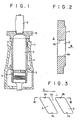
- Figure 1 schematically illustrates a part of an uniflow type two cycle internal combustion engine, wherein reference numeral 1 designates a cylinder liner, reference numeral 2 does a number of scavenging holes, reference 3 does a cylinder, reference numeral 6 does a piston, reference numeral 7 does a cylinder jacket, reference numeral 8 does a cylinder cover and reference numeral 9 does an exhaust valve.
- the conventional uniflow type two cycle internal combustion engine usually has a number of scavenging holes 2 arranged in an equally spaced relation along the cylindrical wall of the cylinder liner 1 at its lower part by way of which fresh air is caused to flow into the interior of the cylinder 3 thereby to expell combustion gas upwardly in the axial direction.
- combustion gas is replaced with fresh air required for next combustion.
- each of the scavenging holes 2 is formed in such a manner that the center line 5 extending on the lower edge surface 2a is directed toward the center 4 of the cylinder and the upper edge surface 2 b is offset from the lower edge surface 2a as illustrated in Figure 3 while the direction of extension of both the upper and lower edge surfaces 2a and 2 b is maintained unchanged.
- the whole air passage extending through the wall of the cylinder liner 1 is inclined in the same direction as that of swirl flow S.
- the upper edge surface 2 b of the scavenging hole extends inwardly in the radial direction with a certain offset from the center 4 of the cylinder equal to a radius R as illustrated in Figure 4. Due to the arrangement of the scavenging holes made in that way fresh air flows into the interior of the cylinder 3 toward the center 4 thereof at the lower part of the scavenging holes 2 but it flows thereinto at the upper part of the latter while it swirls in the horizontal direction.
- the section A occupies the largest space in the cylinder and acts as a significant factor of adversely affecting scavenging efficiency. Further, the A section is an area where comparatively stable gas flow is achieved and the higher pressure difference between both the inside and outside of the cylinder 3 is, the bigger the space occupied by the section A becomes. As far as an internal combustion engine employing high scavenging pressure is concerned, it is an essential requirement that this section is reduced or minimized.
- the present invention has been made with the above-mentioned background in mind and its object resides in providing an improved cylinder linear for an uniflow type two cycle internal combustion engine which assures that improved scavenging efficiency is achieved while ribs between adjacent scavenging holes are configured properly.
- object of the present invention is to provide an improved cylinder liner for an uniflow type two cycle internal combustion engine which assures that ribs have a sufficiently high mechanical strength and scavenging holes have sufficient area in total while the configuration of the ribs on the inner wall of the cylinder is designed so that good lubrication is achieved when a piston passes by the scavenging holes.
- Another object of the present invention is to provide an improved cylinder liner for an uniflow type two cycle internal combustion engine which can be manufactured with reduced working hours.
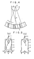
- FIGS 6(a) to (c) schematically illustrate the construction of a cylinder liner in accordance with the first embodiment of the invention.
- the center line Y 1 -Y 1 extending across the outer opening 2 d of the scavenging hole on the outer peripheral surface of the cylinder liner is inclined at an angle of a, relative to the axis line Z-Z of the same.
- the direction of inclination of the angle a is oriented opposite to that of the swirl flow S.
- the center line Y 2 -Y 2 extending across the inner opening 2 e of the scavenging hole on the inner peripheral surface of the cylinder liner is inclined at an angle of a 2 relative to the axis line Z-Z of the same, wherein said inclination angle a 2 is determined less than that of the conventional cylinder liner, as is readily seen from Figure 6(a). It results that the center line Y 1 -Y 1 on the outer opening formed on the outer peripheral surface of the cylinder liner is inclined at angle of ⁇ 1 + ⁇ 2 (>0) relative to the other center line Y 2 -Y 2 on the inner opening formed on the inner peripheral surface of the same.
- Figure 6(b) is a fragmental cross-sectional view of the cylinder liner taken in line A-A in Figure 6(a)
- Figure 6(c) is a fragmental cross-sectional view similar to Figure 6(b) taken in line B-B in Figure 6(a).
- the swirl angle 8 2 at the upper edge surface of the scavenging hole is designed substantially larger than the swirl angle 8 1 at the lower edge surface 2a of the same and the swirl angle ⁇ ' 2 at the central part of the scavenging hole is designed appreciably larger than the swirl angle 8 1 at the lower edge surface 2a of the cylinder liner.
- the scavenging hole extends through the cylinder liner while it is increasingly twisted away from the vertical plane in the above-described manner.
- each of the scavenging hole ribs 2 c has a reduced inclination angle ⁇ 2 on the inner surface of the cylinder liner, it is assured that excellent lubrication is achieved when piston rings pass by the scavenging holes 2.
- FIGS 7(a) to (c) schematically illustrate . the construction of a cylinder liner in accordance with the second embodiment of the invention.
- this embodiment corresponds to the case where the inclination angle ⁇ 2 in the first embodiment as illustrated in Figure 6 liner becomes zero and therefore the center line Y 1 -Y 1 extending across the outer opening of the scavenging hole 2 on the outer peripheral surface of the cylinder liner is inclined at an angle of ⁇ 1 - ⁇ 2 (>0) relative to the center line Y 2 -Y 2 extending across the inner opening on the inner peripheral surface of the same.
- the center line Y 2 -Y 2 is superimposed on the axis line Z-Z of the cylinder.
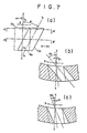
- FIGS 8(a) to (c) schematically illustrate the construction of a cylinder liner in accordance with the third embodiment of the invention.
- the center line Y 2 -Y 2 extending across the inner opening of the scavenging hole 2 on the inner peripheral surface of the cylinder liner is inclined at an angle a 2 relative to the center axis Z-Z of the cylinder in the same direction as the center line Y 1 -Y 1 extending across the outer opening on the outer peripheral surface of the same, the latter being inclined at an angle ⁇ 1 relative to the center axis Z-Z of the cylinder.
- center line Y 1 -Y 1 is inclined at an angle of ⁇ 1 - ⁇ 2 (>0) relative to the center line Y 2 -Y 2 but the cylinder liner in accordance with this embodiment functions in the substantially same manner as in the first embodiment.
- the cylinder liner in accordance with any one of the first to third embodiments is constructed in such a manner that the center line Y 1 -Y 1 extending across the outer opening of the scavenging hole is inclined in the opposite direction to that of the swirl S.
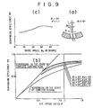
- Figures 9(a) to (c) illustrates improvement in scavenging efficiency which can be achieved by the construction of the scavenging holes on the cylinder liner in accordance with the first to third embodiments of the invention.
- Figures 9(b) and (c) show results of experiments which were conducted under the operating conditions where swirl angle 8 1 at the lower edge surface of the scavenging hole is fixedly determined to 5 degrees and swirl angle 8 2 on the upper edge surface of the same varies in the range of 10 to 40 degrees, as illustrated in Figure 9(a).
- Figure 9(b) illustrates by way of diagrams a relation between air intake ratio p and scavenging efficiency ⁇ s , wherein the angles 8, and 6 2 serve as a parameter
- Figure 9(c) does a relation between swirl angle 8 2 and scavenging efficiency ⁇ s , wherein swirl angle 8, is fixedly determined to 5 degrees and air intake ratio p is fixedly determined to 1.1.
- a cylinder liner for an uniflow type two cycle inner combustion engine in accordance with the first to third embodiments of the invention is constructed such that the center line Y 1 -Y 1 extending across the outer opening of each of the scavenging holes on the outer peripheral surface of the cylinder liner is inclined in the opposite direction to that of the swirl flow S and the upper swirl angle 8 2 is determined larger than the lower swirl angle 8' 2 so that air passage extending through the scavenging holes is twisted away from the vertical plane.
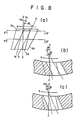
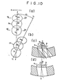
- Figures 10(a) to (d) schematically illustrate a cylinder liner in accordance with the fourth embodiment of the invention, wherein Figures 10(a) and (b) are a fragmental view of a scavenging hole as seen from the position located outwardly of the peripheral surface of the cylinder liner.
- the axis line Y 1 -Y 1 extending across the outer opening 2, of the scavenging hole on the outer peripheral surface of the cylinder liner (linear line extending through both the center O 1 of the lower hole and the center O 3 of the upper hole) is inclined at an angle of ⁇ 1 relative to the axis line Z-Z of the cylinder.
- the axis line Y 1 -Y 1 is inclined in the opposite direction to that of the swirl S as illustrated in Figures 10(c) and (d). Further, the axis line Y 2 -Y 2 extending across the inner opening 2 e of the scavenging hole on the inner peripheral surface of the cylinder liner is superimposed on the axis line Z-Z of the cylinder as is apparent from Figure 10(a). Accordingly, the axis line Y 1 -Y 1 extending across the outer opening on the outer peripheral surface of the cylinder liner is inclined at an angle of ⁇ 1 relative to the axis line Y 2 -Y 2 extending across the inner opening on the inner peripheral surface of the same.
- Figure 10(c) is a fragmental cross-sectional view of the cylinder liner taken in line A-A in Figure 10(a) and Figure 10(d) is a fragmental cross-sectional view of the same taken in line B-B in Figure 10(a).
- the swirl angle 8 3 at the upper hole part of the scavenging hole is determined substantially larger than the swirl angle ⁇ 1 at the lower hole part of the same.
- the swirl angle 8 2 of the central part of the scavenging hole is determined appreciably larger than the swirl angle 8, of the lower part of the same. Accordingly, the following inequality will be established
- the scavenging hole extends through the cylinder liner while it is increasingly twisted away from the vertical plane in the above-described manner.
- the centers (O i , O' i ), (0 2 , 0' 2 ) and (0 3 , 0' 3 ) of both the outer and inner openings of the scavenging hole are located on a plane extending at a right angle relative to the axis line Z-Z of the cylinder respectively.
- the inner opening on the inner peripheral surface of the cylinder liner at each of the upper, central and lower parts of the scavenging hole has the same width B as measured in the peripheral direction.
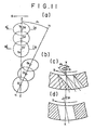
- Figures 11 (a) to (d) schematically illustrate a cylinder liner in accordance with the fifth embodiment of the invention.
- the center O2 of the central part of the scavenging hole is located in alignment with the axis line Y 1 -Y 1 which extends through both the center 0, of the lower part and the center 0 3 of the upper part as is the case with the fourth embodiment illustrated in Figure 10(b).
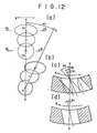
- FIGS 12(a) to (d) schematically illustrate a cylinder liner in accordance with the sixth embodiment of the invention.
- This embodiment is substantially same to the foregoing ones as illustrated in Figures 10 and 11 with exception that each of hole parts constituting the scavenging hole has the same inner diameter.
- each of the hole parts on the inner peripheral surface of the cylinder liner has the same width as measured in the peripheral direction as in case of the foregoing embodiments illustrated in Figures 10 and 11, it results that the inner diameter of each of the hole parts is caused to decrease as each of the swirl angles 8 1 , ⁇ 2 and 8 3 increases.
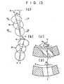
- Figures 13(a) to (d) schematically illustrate a cylinder liner in accordance with the seventh embodiment of the invention.
- the cylinder liner is constructed in the different mannerfrom the fourth embodiment as illustrated in Figure 10 such that the axis line Y 2 -Y 2 extending across the inner opening 2 e on the inner peripheral surface of the cylinder liner is inclined at an angle a 2 relative to the axis line Z-Z of the cylinder in the leftward direction while the axis line Y 1 -Y 1 extending across the outer opening 2 t on the outer peripheral surface of the cylinder liner is inclined at an angle ⁇ 1 relative to the axis line Z-Z of the cylinder in the righthand direction as seen in the drawing.
- the axis line Y 1 -Y 1 on the outer opening of the scavenging hole is inclined by an angle ⁇ 1 + ⁇ 2 (>0) relative to the axis line Y 2 -Y 2 on the inner opening of the same.
- Figures 14(a) to (d) schematically illustrate a cylinder liner in accordance with the eighth embodiment of the invention.
- the axis line Y 2 -Y 2 extending across the inner opening 2 e on the inner peripheral surface of the cylinder liner is inclined at an angle of a 2 relative to the axis line Z-Z of the cylinder in the rightward direction and the axis line Y 1 -Y 1 extending across the outer opening 2 f on the outer peripheral surface of the same is inclined at an angle of ⁇ 1 relative to the axis line Z-Z of the cylinder in the rightward direction as seen in the drawing, that is, in the same direction as that of the axis line Y 2 -Y 2 .
- the axis line Y,-Y is inclined at an angle ⁇ 1 - ⁇ 2 (>0) relative to the axis line Y 2 -Y 2 .
- the cylinder liner in accordance with any one of the fourth to eighth embodiments is constructed such that the axis line Y 1 -Y 1 extending across the outer opening of the scavenging hole is inclined in the opposite direction to that of the swirl flow S as in case of the first to third embodiments.
- the cylinder liner in accordance with the fifth embodiment as illustrated in Figure 11 has no inclination relative to the axis line Z-Z of the cylinder and the cylinder liner in accordance with the fourth and sixth embodiments as illustrated in Figures 10 and 12 has a certain inclination less than that of the ribs on the conventional cylinder liner. Owing to the arrangement made in that way it is assured that excellent lubrication is achieved when piston rings pass by the scavenging holes.
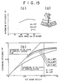
- Figures 15(a) to (c) illustrates improvement in scavenging efficiency which can be achieved by the construction of the scavenging holes on the cylinder liner in accordance with the fourth to eighth embodiments of the invention, wherein Figure 15(a) is a fragmental cross-sectional view of the cylinder liner particularly illustrating how swirl angles 8 1 , 8 2 and 8 3 are determined and Figures 15 (b) and (c) show results of experiments which were conducted under the operating conditions where swirl angle 8 1 at the lower hole part is fixedly determined to 5 degrees, swirl angle 8 2 at the central hole part is fixedly determined to 10 degrees and swirl angle 8 3 at the upper hole part varies at three stages of 20, 30 and 40 degrees.
- Figure 15(b) illustrates by way of diagrams a relation between air intake ratio p and scavenging efficiency ⁇ s with swirl angle 8 3 fixedly determined as a parameter and Figure 15(c) does a relation between swirl angle 8 3 and scavenging efficiency ⁇ s when swirl angle 8 1 is fixedly determined to 5 degrees, swirl angle 8 2 is fixedly determined to 10 degrees and air intake ratio p is fixedly determined to 1.1.
- scavenging efficiency ⁇ s increases as swirl angle 8 3 increases in the range of 20 to 30 degrees and it reaches the highest level when swirl angle 8 3 is determined to 30 degrees or more or less.
- Inclination angles ⁇ 1 and ⁇ 2 of the scavenging holes are determined as function relative to height of scavenging holes, number of the latter and swirl angles. Since each of the scavenging holes on the cylinder liner in accordance with the fourth to eighth embodiments of the invention is constructed by a combination of plural circular holes, it is assured that it has a large swirl angle 8 3 at its upper hole part and a small swirl angle 8 1 at its lower hole part while each of the ribs between the adjacent scavenging holes has a proper configuration with working hours required forforming them being reduced to the minimum, resulting in improved scavenging efficiency guaranteed.
- a cylinder liner for an uniflowtypetwo cycle internal combustion engine in accordance with the fourth to eighth embodiments is constructed so that each of scavenging holes comprises a combination of plural circular holes which are arranged in an end-to-end relation in the substantially axial direction of the cylinder liner in such a manner that the axis line Y 1 -Y 1 extending through the center of the lowermost hole part and the center of the uppermost hole part on the outer opening of the scavenging hole on the outer peripheral surface of the cylinder liner is inclined in the opposite direction to that of the scavenging swirl flow S, wherein the upper swirl angle 8 3 is determined larger than the lower swirl angle 8 1 so that the center line extending through the center of each of the hole parts constituting the scavenging hole is twisted away from the vertical plane.
- each of the scavenging holes is formed with the minimized working hours required while ribs between the adjacent scavenging holes have proper configuration and sufficiently high strength and moreover remarkably improved scavenging efficiency is achieved with excellent lubricating function being maintained when the piston passes by the scavenging holes.
Landscapes
- Engineering & Computer Science (AREA)
- Chemical & Material Sciences (AREA)
- Combustion & Propulsion (AREA)
- Mechanical Engineering (AREA)
- General Engineering & Computer Science (AREA)
- Cylinder Crankcases Of Internal Combustion Engines (AREA)
- Pistons, Piston Rings, And Cylinders (AREA)
Claims (11)
Applications Claiming Priority (4)
| Application Number | Priority Date | Filing Date | Title |
|---|---|---|---|
| JP19250982A JPS5985425A (ja) | 1982-11-04 | 1982-11-04 | ユニフロ−2サイクルエンジンのシリンダライナ |
| JP192509/82 | 1982-11-04 | ||
| JP19596782A JPS5987226A (ja) | 1982-11-10 | 1982-11-10 | ユニフロ−2サイクルエンジンのシリンダライナ |
| JP195967/82 | 1982-11-10 |
Publications (3)
| Publication Number | Publication Date |
|---|---|
| EP0108706A2 EP0108706A2 (de) | 1984-05-16 |
| EP0108706A3 EP0108706A3 (en) | 1985-12-18 |
| EP0108706B1 true EP0108706B1 (de) | 1988-08-24 |
Family
ID=26507358
Family Applications (1)
| Application Number | Title | Priority Date | Filing Date |
|---|---|---|---|
| EP83730100A Expired EP0108706B1 (de) | 1982-11-04 | 1983-10-21 | Zylinderbüchse einer Zweitaktbrennkraftmaschine vom Gleichstromtyp |
Country Status (4)
| Country | Link |
|---|---|
| EP (1) | EP0108706B1 (de) |
| KR (1) | KR840007136A (de) |
| DE (1) | DE3377804D1 (de) |
| DK (1) | DK157701C (de) |
Families Citing this family (5)
| Publication number | Priority date | Publication date | Assignee | Title |
|---|---|---|---|---|
| IT1188374B (it) * | 1985-03-19 | 1988-01-07 | Sulzer Ag | Motore endotermico a stantuffo a due tempi con valvola di scarico montata nella testata |
| EP0198816A3 (de) * | 1985-04-05 | 1987-11-25 | AVL Gesellschaft für Verbrennungskraftmaschinen und Messtechnik mbH.Prof.Dr.Dr.h.c. Hans List | Zweitakt-Brennkraftmaschine |
| FR3020656B1 (fr) * | 2014-05-05 | 2020-08-14 | Renault Sas | "moteur thermique deux temps de vehicule automobile a lumieres d'admission vrillees" |
| EP3175100B1 (de) * | 2014-08-01 | 2020-08-26 | Renault s.a.s. | Zweitaktbrennkraftmaschine eines kraftfahrzeugs mit verdehten einlasskanälen mit seitlichen geraden kanten |
| CN114542316B (zh) * | 2022-03-09 | 2024-08-20 | 广西玉柴机器股份有限公司 | 气缸套结构 |
Family Cites Families (6)
| Publication number | Priority date | Publication date | Assignee | Title |
|---|---|---|---|---|
| US1732856A (en) * | 1926-12-16 | 1929-10-22 | Pawlikowski Rudolf | Cylinder for piston engines |
| CH200570A (de) * | 1936-09-30 | 1938-10-15 | Messerschmitt Boelkow Blohm | Zylinder für Brennkraftmaschinen mit kolbengesteuerten Einlassöffnungen. |
| DE736326C (de) * | 1936-12-20 | 1943-06-11 | Buessing Nag Vereinigte Nutzkr | Zweitaktbrennkraftmaschine mit Gleichstromspuelung |
| DE754166C (de) * | 1939-12-28 | 1952-12-15 | Forschungsanstalt Prof Junkers | Zweitaktbrennkraftmaschine mit Gleichstromspuelung |
| US2720195A (en) * | 1954-04-16 | 1955-10-11 | Gen Motors Corp | Two-cycle engine |
| GB851353A (en) * | 1956-07-04 | 1960-10-12 | North Eastern Marine Engineeri | Improvements in or relating to cylinder liners for use in large internal combustion engines |
-
1983
- 1983-10-19 KR KR1019830004932A patent/KR840007136A/ko not_active Withdrawn
- 1983-10-21 EP EP83730100A patent/EP0108706B1/de not_active Expired
- 1983-10-21 DE DE8383730100T patent/DE3377804D1/de not_active Expired
- 1983-11-03 DK DK503283A patent/DK157701C/da not_active IP Right Cessation
Also Published As
| Publication number | Publication date |
|---|---|
| DK503283D0 (da) | 1983-11-03 |
| KR840007136A (ko) | 1984-12-05 |
| DK157701C (da) | 1990-06-25 |
| DK157701B (da) | 1990-02-05 |
| EP0108706A3 (en) | 1985-12-18 |
| DK503283A (da) | 1984-05-05 |
| DE3377804D1 (en) | 1988-09-29 |
| EP0108706A2 (de) | 1984-05-16 |
Similar Documents
| Publication | Publication Date | Title |
|---|---|---|
| US4329968A (en) | Oil separating system for blowby gas | |
| EP0992660B1 (de) | Schichtspülung für zweitaktmotoren | |
| US7963258B2 (en) | Air intake porting for a two stroke engine | |
| JP6096684B2 (ja) | 一体形オイルセパレータを有するエンジンヘッドカバー組立品 | |
| EP0118772A1 (de) | Kolben für Hubkolbenbrennkraftmaschine | |
| EP0108706B1 (de) | Zylinderbüchse einer Zweitaktbrennkraftmaschine vom Gleichstromtyp | |
| US7096843B2 (en) | Multicylinder four-cycle combustion engine | |
| US7294030B2 (en) | Outboard motor having seal structure for exhaust release pipe | |
| EP1818530A1 (de) | Schmiervorrichtung für zylinderinnenwand in einem zweitakt-verbrennungsmotor | |
| US5611302A (en) | Two cycle internal combustion engine with unidirectional flow scavenging | |
| EP0064457B2 (de) | Zylinderblock für eine Brennkraftmaschine | |
| KR100422513B1 (ko) | 블로바이가스의 오일 분리장치 | |
| JPH0323740B2 (de) | ||
| US4964382A (en) | Piston for two-cycle internal combustion engine | |
| US12044312B2 (en) | Piston for an internal combustion engine | |
| EP0529935A1 (de) | Diesel-Viertaktmotor | |
| JPS6363724B2 (de) | ||
| KR880001725Y1 (ko) | 단류 2사이클엔진의 실린더라이너 | |
| JPS643791Y2 (de) | ||
| JPH08121243A (ja) | 内燃機関用のピストン | |
| JP2004257371A (ja) | 時間差掃気2サイクルエンジン | |
| JPH0610758A (ja) | 2サイクルディーゼル機関の掃気孔 | |
| JPS6258015A (ja) | 2サイクルエンジン | |
| JPH0542659U (ja) | 内燃機関のシリンダライナ |
Legal Events
| Date | Code | Title | Description |
|---|---|---|---|
| PUAI | Public reference made under article 153(3) epc to a published international application that has entered the european phase |
Free format text: ORIGINAL CODE: 0009012 |
|
| AK | Designated contracting states |
Designated state(s): CH DE FR GB LI NL SE |
|
| 17P | Request for examination filed |
Effective date: 19840417 |
|
| PUAL | Search report despatched |
Free format text: ORIGINAL CODE: 0009013 |
|
| AK | Designated contracting states |
Designated state(s): CH DE FR GB LI NL SE |
|
| 17Q | First examination report despatched |
Effective date: 19861007 |
|
| D17Q | First examination report despatched (deleted) | ||
| GRAA | (expected) grant |
Free format text: ORIGINAL CODE: 0009210 |
|
| AK | Designated contracting states |
Kind code of ref document: B1 Designated state(s): CH DE FR GB LI NL SE |
|
| REF | Corresponds to: |
Ref document number: 3377804 Country of ref document: DE Date of ref document: 19880929 |
|
| ET | Fr: translation filed | ||
| PLBE | No opposition filed within time limit |
Free format text: ORIGINAL CODE: 0009261 |
|
| STAA | Information on the status of an ep patent application or granted ep patent |
Free format text: STATUS: NO OPPOSITION FILED WITHIN TIME LIMIT |
|
| 26N | No opposition filed | ||
| REG | Reference to a national code |
Ref country code: GB Ref legal event code: 746 |
|
| REG | Reference to a national code |
Ref country code: FR Ref legal event code: DL |
|
| PGFP | Annual fee paid to national office [announced via postgrant information from national office to epo] |
Ref country code: FR Payment date: 19931011 Year of fee payment: 11 |
|
| PGFP | Annual fee paid to national office [announced via postgrant information from national office to epo] |
Ref country code: SE Payment date: 19931015 Year of fee payment: 11 |
|
| PG25 | Lapsed in a contracting state [announced via postgrant information from national office to epo] |
Ref country code: SE Effective date: 19941022 |
|
| PGFP | Annual fee paid to national office [announced via postgrant information from national office to epo] |
Ref country code: NL Payment date: 19941031 Year of fee payment: 12 |
|
| EAL | Se: european patent in force in sweden |
Ref document number: 83730100.1 |
|
| PG25 | Lapsed in a contracting state [announced via postgrant information from national office to epo] |
Ref country code: FR Effective date: 19950630 |
|
| EUG | Se: european patent has lapsed |
Ref document number: 83730100.1 |
|
| REG | Reference to a national code |
Ref country code: FR Ref legal event code: ST |
|
| PG25 | Lapsed in a contracting state [announced via postgrant information from national office to epo] |
Ref country code: NL Effective date: 19960501 |
|
| NLV4 | Nl: lapsed or anulled due to non-payment of the annual fee |
Effective date: 19960501 |
|
| PGFP | Annual fee paid to national office [announced via postgrant information from national office to epo] |
Ref country code: GB Payment date: 19961014 Year of fee payment: 14 |
|
| PGFP | Annual fee paid to national office [announced via postgrant information from national office to epo] |
Ref country code: CH Payment date: 19961104 Year of fee payment: 14 |
|
| PG25 | Lapsed in a contracting state [announced via postgrant information from national office to epo] |
Ref country code: GB Free format text: LAPSE BECAUSE OF NON-PAYMENT OF DUE FEES Effective date: 19971021 |
|
| PG25 | Lapsed in a contracting state [announced via postgrant information from national office to epo] |
Ref country code: LI Free format text: LAPSE BECAUSE OF NON-PAYMENT OF DUE FEES Effective date: 19971031 Ref country code: CH Free format text: LAPSE BECAUSE OF NON-PAYMENT OF DUE FEES Effective date: 19971031 |
|
| GBPC | Gb: european patent ceased through non-payment of renewal fee |
Effective date: 19971021 |
|
| REG | Reference to a national code |
Ref country code: CH Ref legal event code: PL |
|
| PGFP | Annual fee paid to national office [announced via postgrant information from national office to epo] |
Ref country code: DE Payment date: 19981103 Year of fee payment: 16 |
|
| PG25 | Lapsed in a contracting state [announced via postgrant information from national office to epo] |
Ref country code: DE Free format text: LAPSE BECAUSE OF NON-PAYMENT OF DUE FEES Effective date: 20000801 |