EP0108044A2 - Wasserflussregeleinrichtung zum Kühlen von Bohrlöchern bei der Vergasung von Kohle - Google Patents
Wasserflussregeleinrichtung zum Kühlen von Bohrlöchern bei der Vergasung von Kohle Download PDFInfo
- Publication number
- EP0108044A2 EP0108044A2 EP83870092A EP83870092A EP0108044A2 EP 0108044 A2 EP0108044 A2 EP 0108044A2 EP 83870092 A EP83870092 A EP 83870092A EP 83870092 A EP83870092 A EP 83870092A EP 0108044 A2 EP0108044 A2 EP 0108044A2
- Authority
- EP
- European Patent Office
- Prior art keywords
- water
- chamber
- piston
- water flow
- enclosure
- Prior art date
- Legal status (The legal status is an assumption and is not a legal conclusion. Google has not performed a legal analysis and makes no representation as to the accuracy of the status listed.)
- Granted
Links
Images

Classifications
-
- E—FIXED CONSTRUCTIONS
- E21—EARTH OR ROCK DRILLING; MINING
- E21B—EARTH OR ROCK DRILLING; OBTAINING OIL, GAS, WATER, SOLUBLE OR MELTABLE MATERIALS OR A SLURRY OF MINERALS FROM WELLS
- E21B36/00—Heating, cooling or insulating arrangements for boreholes or wells, e.g. for use in permafrost zones
- E21B36/001—Cooling arrangements
-
- E—FIXED CONSTRUCTIONS
- E21—EARTH OR ROCK DRILLING; MINING
- E21B—EARTH OR ROCK DRILLING; OBTAINING OIL, GAS, WATER, SOLUBLE OR MELTABLE MATERIALS OR A SLURRY OF MINERALS FROM WELLS
- E21B34/00—Valve arrangements for boreholes or wells
- E21B34/06—Valve arrangements for boreholes or wells in wells
-
- G—PHYSICS
- G05—CONTROLLING; REGULATING
- G05D—SYSTEMS FOR CONTROLLING OR REGULATING NON-ELECTRIC VARIABLES
- G05D9/00—Level control, e.g. controlling quantity of material stored in vessel
- G05D9/04—Level control, e.g. controlling quantity of material stored in vessel with auxiliary non-electric power
Definitions
- the present invention relates to a regulator of the water flow rate of a device for cooling a gas discharge pipe, produced by gasification of an underground coal deposit, comprising near its base an enclosure in which the liquid phase of water is in contact with the vapor phase.
- Belgian patent No 847 383 describes the cooling of the gas in a heat exchanger supplied with water from the surface, so as to produce steam which is then mixed with the gas stream. Some authors have proposed spraying water directly into the gas stream.
- a characteristic common to these systems is the difficulty of regulating the flow of water injected.
- a precise adjustment is necessary given that too little water leads to overheating and destruction of the casing, and that too much water causes disturbances in the flow of gas, or even the invasion of the borehole.
- the present invention provides a flow regulator which satisfies the conditions mentioned above.
- a regulator of the water flow of a device for cooling a gas evacuation pipe, produced by gasification of an underground coal deposit comprising near its base an enclosure in which the liquid phase water is in contact with the vapor phase, essentially characterized in that the entry of water into the enclosure of the device for cooling the pipe for discharging the gas produced by gasification of an underground coal deposit is controlled by a piston which can move in a substantially closed chamber; this piston, comprising a water inlet pipe, is subjected on the one hand to the pressure of the water coming from the surface and on the other hand to the force of a spring; this room also has an adjustable orifice, controlled by a needle, allowing the water contained in the room to exit.
- all the side walls of the chamber, the spring and the piston are replaced by an expansion bellows secured to a unit for controlling the entry of water and secured of the adjustable opening allowing the water to exit from the bellows.
- the water inlet control unit consists of an elongated body forming the shutter of the enclosure; this body is shaped externally so as to present alternately conical zones and cylindrical zones and moves axially in a cylindrical space whose walls include narrowing.
- the water inlet conduit passing through the elongated body consists at least partially of a succession of restrictions and widenings.
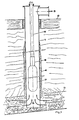
- FIG. 1 shows a borehole 1 connecting the surface 2 to a coal deposit 3.
- the refractory cement 4 surrounds the borehole 1.
- the gas produced is represented by the arrows bearing the reference number 5.
- a water supply pipe 6 comprising at the bottom a heat exchanger 7 provided with a flow regulator 8.
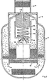
- FIG. 2 shows the cooling device comprising an enclosure 11 in which the liquid phase 9 of the water is in equilibrium with the vapor phase 10.
- a flow regulator comprising a piston 12 whose head acts as a shutter for the orifice 13 located at the foot of the tube 6 bringing the water under high pressure (for example 100 bars) from the surface.
- the bottom of the cylinder 14 is pierced with a small orifice 15 allowing the water contained in the cylinder to escape from it.
- This outlet 15 is controlled by a needle 16 whose position is fixed by the water level in the heat exchanger 7, ensuring the cooling of the gas.
- a float 17 is connected to the needle 16 by a set of levers 18.
- a spring 19 inserted in the cylinder 14 opposes the displacement of the piston 12 downwards. The equilibrium position of the piston is obtained when the resultant of the forces exerted on it is zero.
- This device therefore constitutes a servomechanism amplifying both the displacement and the force of the regulating member 8 by making use of the potential energy available in the water upstream of the regulator.
- the stroke of the piston 12 is of the order of 10 times that of the needle 16 and the force applied to the shutter 13 of the order of 300 times that exerted on the needle 16.
- the movement of the needle 16 is controlled by a float 17 which follows the movement of the water level in the device 7.
- the operation of the entire adjusting device 8 is summarized as follows. Suppose that the water level drops in the exchanger 7; the float 17 accompanies this descent and transmits its displacement to the needle 16 which in turn descends and reduces the resistance offered at 15 to the exhaust of the secondary flow. Consequently, the pressure falls in the chamber 14, the piston 12 descends and the main shutter 21 opens, increasing the main flow until finding a new balance. The process is reversed when the level rises in the exchanger 7.
- the leakage rate around the piston 12 must remain negligible compared to the incoming and outgoing rates. Moreover, if the leakage rate becomes high, it could cause an additional head loss upstream such that the pressure in the chamber 14 can no longer reach a value sufficient to close the shutter 13. According to a form of implementation, one can replace all the side walls of the chamber 14 - piston 12 - spring 19 by an expansion bellows sealingly connecting to the shutter 13. In order to control the temperature in the production probes 1 , it is necessary to modulate the flow of water precisely in a wide range, for example, between 10 to 100% of the nominal flow.
- this invention proposes a shutter with an original geometry.
- this shows an expansion bellows 22 integral with a unit for controlling the entry of water.
- This unit comprises an elongated body 23 and consists of a plurality of conical zones 33 alternating with cylindrical zones 25 and 26.
- This body 23 moves in a cylindrical space whose walls 27 have annular sections 28.
- the parts 29 and 30 guide the body 23.
- the cylindrical parts 25 are opposite the annular sections 28, the sections are the narrowest and allow a minimum flow to pass; a shutter 31 located at the head makes it possible to cancel this flow in the closed position.
- the conical parts 24 appear opposite the parts 28. Given the conicity, a gradual and linear variation is obtained in the narrowed sections (and therefore in the flow rate) as the body descends.
- the number of constrictions is adapted to the pressure drop to be achieved and therefore to the depth of the gasification borehole.
- the moving water column above the regulating member 8 has a large mass and inertia.
- the mass exceeds 1 ton for a pipe 5cm in diameter and 1000m in length.
- a too rapid closing action of the regulator 8 generates powerful pressure surges.
- the speed of movement of the shutter body 21 is limited during the closing phase. Indeed, during this phase, the incoming secondary flow is increased relative to the outgoing flow by an additional flow necessary to inflate the bellows.
- the closing speed of the regulator and therefore the speed of variation of the flow rate can be chosen as desired, so as to reduce the overpressure in the upstream pipe as much as necessary during closing.
- the conduit 20 is equipped with a succession of restrictions 32 and widenings 33. With each restriction, the water acquires kinetic energy which it loses in the next widened zone where the flow is strongly turbulent.
- the number of stages of the labyrinth must be adapted to the importance of the upstream pressure and therefore to the depth of the borehole.
- the components described must be assembled in a cylindrical volume. as narrow as possible, so that it can be easily slid inside the sounding casing.
- the secondary labyrinth 32-33 is placed above the main labyrinth 24-25-26-28.
- direct control of the movement of the needle can be obtained by the temperature of the gases downstream of the exchanger.
- the needle can be fixed to a stirrup supported by rods placed in the gas stream around the enclosure and made of a material with a high coefficient of expansion.
- the needle can also be mounted on a membrane of a manometric capsule, so when the pressure drops, the membrane drops and causes the regulator to open; and vice versa.
Landscapes
- Engineering & Computer Science (AREA)
- Geology (AREA)
- Life Sciences & Earth Sciences (AREA)
- Mining & Mineral Resources (AREA)
- Physics & Mathematics (AREA)
- Environmental & Geological Engineering (AREA)
- Fluid Mechanics (AREA)
- General Life Sciences & Earth Sciences (AREA)
- Geochemistry & Mineralogy (AREA)
- Power Engineering (AREA)
- General Physics & Mathematics (AREA)
- Automation & Control Theory (AREA)
- Flow Control (AREA)
Applications Claiming Priority (2)
| Application Number | Priority Date | Filing Date | Title |
|---|---|---|---|
| LU84383 | 1982-09-20 | ||
| LU84383A LU84383A1 (fr) | 1982-09-20 | 1982-09-20 | Regulateur de debit d'eau de refroidissement pour sondages de gazeification souterraine |
Publications (3)
| Publication Number | Publication Date |
|---|---|
| EP0108044A2 true EP0108044A2 (de) | 1984-05-09 |
| EP0108044A3 EP0108044A3 (en) | 1984-10-17 |
| EP0108044B1 EP0108044B1 (de) | 1988-01-13 |
Family
ID=19729949
Family Applications (1)
| Application Number | Title | Priority Date | Filing Date |
|---|---|---|---|
| EP19830870092 Expired EP0108044B1 (de) | 1982-09-20 | 1983-09-19 | Wasserflussregeleinrichtung zum Kühlen von Bohrlöchern bei der Vergasung von Kohle |
Country Status (4)
| Country | Link |
|---|---|
| EP (1) | EP0108044B1 (de) |
| DE (1) | DE3375311D1 (de) |
| LU (1) | LU84383A1 (de) |
| PL (1) | PL243825A1 (de) |
Family Cites Families (14)
| Publication number | Priority date | Publication date | Assignee | Title |
|---|---|---|---|---|
| US3359997A (en) * | 1965-05-14 | 1967-12-26 | Rolf H Gardey | Flow-control valve |
| US3489165A (en) * | 1968-10-30 | 1970-01-13 | Vapor Corp | Inline pressure regulator |
| FR2109165A5 (de) * | 1970-10-06 | 1972-05-26 | Avco Corp | |
| US3715098A (en) * | 1971-07-06 | 1973-02-06 | H Baumann | Adjustable fluid restrictor method and apparatus |
| US3893475A (en) * | 1973-10-05 | 1975-07-08 | George D Hudson | Float valve |
| DE2611179A1 (de) * | 1976-03-17 | 1977-10-06 | Gulde Regelarmaturen Kg | Verfahren zur kavitationsfreien mehrstufigen entspannung von fluessigkeiten in regelarmaturen |
| FR2356195A1 (fr) * | 1976-06-25 | 1978-01-20 | Commissariat Energie Atomique | Circuit de refroidissement de securite notamment pour reacteurs nucleaires |
| SE400357B (sv) * | 1976-07-06 | 1978-03-20 | Kockums Ab | Tryckmediestyrd ventil |
| BE847383A (fr) * | 1976-10-15 | 1977-01-31 | Procede et appareillage pour le refroidissement desgaz de gazeification souterraine des gisements de combustibles solides ou des gaz proveneant de gisements petroliers exploites par comustiion "in situ". | |
| US4159743A (en) * | 1977-01-03 | 1979-07-03 | World Energy Systems | Process and system for recovering hydrocarbons from underground formations |
| FR2408086A1 (fr) * | 1977-11-02 | 1979-06-01 | Trubert Denis | Dispositif pour la commande automatique de la fermeture du robinet de remplissage d'un appareil sanitaire, en particulier d'une baignoire, lorsque le liquide recueilli atteint un niveau predetermine |
| FR2427999A1 (fr) * | 1978-06-09 | 1980-01-04 | Sam Ste Nle | Dispositif limiteur de remplissage d'un reservoir de stockage |
| NL8100326A (nl) * | 1981-01-23 | 1982-08-16 | Valico Pvba | Op een tank gemonteerd vulmechanisme. |
| US4377205A (en) * | 1981-03-06 | 1983-03-22 | Retallick William B | Low pressure combustor for generating steam downhole |
-
1982
- 1982-09-20 LU LU84383A patent/LU84383A1/fr unknown
-
1983
- 1983-09-19 DE DE8383870092T patent/DE3375311D1/de not_active Expired
- 1983-09-19 EP EP19830870092 patent/EP0108044B1/de not_active Expired
- 1983-09-20 PL PL24382583A patent/PL243825A1/xx unknown
Also Published As
| Publication number | Publication date |
|---|---|
| DE3375311D1 (en) | 1988-02-18 |
| EP0108044A3 (en) | 1984-10-17 |
| PL243825A1 (en) | 1984-04-24 |
| LU84383A1 (fr) | 1984-04-24 |
| EP0108044B1 (de) | 1988-01-13 |
Similar Documents
| Publication | Publication Date | Title |
|---|---|---|
| JP4429561B2 (ja) | パイプライン用圧力制御装置 | |
| EP3040591A1 (de) | Flüssige flusskontrolle für schichtabscheidung | |
| FR2757209A1 (fr) | Dispositif et procede d'obturation pour tubages de puits | |
| EP0435716B1 (de) | Vorrichtung zur Separation eines Gas-Flüssigkeitsgemisches als Zufuhr einer Imbohrlochpumpe | |
| FR2672936A1 (fr) | Procede de controle du debit de production d'un puits petrolier. | |
| EP0108044B1 (de) | Wasserflussregeleinrichtung zum Kühlen von Bohrlöchern bei der Vergasung von Kohle | |
| EP3334898B1 (de) | Unterwasseranlage zur gas-flüssigkeitstrennung | |
| FR2695705A1 (fr) | Vanne automatique de purge pour réservoir sous pression. | |
| EP0106755B1 (de) | Verfahren und Einrichtung zum Herbeiführen einer Vielzahl hydrodynamischer Funktionen in einem Strom, zusammengesetzt aus wenigstens zwei Phasen | |
| FR2569760A1 (fr) | Soupape de surete commandee par niveau de fluide | |
| FR2561571A1 (fr) | Dispositif autonome et automatique de production rapide de mousse polyurethane | |
| EP0091850A1 (de) | Automatischer Flüssigkeitsniveauregulator für superfluides Helium in einem Behälter | |
| EP0131499B1 (de) | Verfahren zur Oxydation von kohlenwasserstoffhaltigen untertägigen sedimentären Lagerstätten | |
| EP0478421B1 (de) | Dichtungsvorrichtung mit eine Flüssigkeitsdichtung | |
| FR2499641A1 (fr) | Dispositif a accumulateur hydraulique pour la limitation des contraintes appliquees a une canalisation d'alimentation en fluide | |
| US337350A (en) | Half to enoch h | |
| FR2504152A1 (fr) | Procede d'injection de charbon pulverise dans les tuyeres d'un haut fourneau et installation pour sa mise en oeuvre | |
| BE1005807A3 (fr) | Procede d'extinction de puits de petrole en feu et dispositif de mise en oeuvre. | |
| BE847383A (fr) | Procede et appareillage pour le refroidissement desgaz de gazeification souterraine des gisements de combustibles solides ou des gaz proveneant de gisements petroliers exploites par comustiion "in situ". | |
| EP0128129A2 (de) | Ventil, insbesondere für Flüssiggas | |
| CA2250101A1 (fr) | Procede de pompage d'un fluide | |
| FR2560340A1 (fr) | Regulateur de pression de gaz et installation pour maintenir une pression de gaz dans une enceinte | |
| US871141A (en) | Apparatus for automatically lighting gas-lamps. | |
| RU2656536C1 (ru) | Клапан-отсекатель | |
| FR2477266A1 (fr) | Ensemble a bruleur a combustible liquide |
Legal Events
| Date | Code | Title | Description |
|---|---|---|---|
| PUAI | Public reference made under article 153(3) epc to a published international application that has entered the european phase |
Free format text: ORIGINAL CODE: 0009012 |
|
| AK | Designated contracting states |
Designated state(s): BE DE FR GB NL |
|
| PUAL | Search report despatched |
Free format text: ORIGINAL CODE: 0009013 |
|
| AK | Designated contracting states |
Designated state(s): BE DE FR GB NL |
|
| 17P | Request for examination filed |
Effective date: 19850406 |
|
| 17Q | First examination report despatched |
Effective date: 19870223 |
|
| 17Q | First examination report despatched |
Effective date: 19870331 |
|
| GRAA | (expected) grant |
Free format text: ORIGINAL CODE: 0009210 |
|
| AK | Designated contracting states |
Kind code of ref document: B1 Designated state(s): BE DE FR GB NL |
|
| REF | Corresponds to: |
Ref document number: 3375311 Country of ref document: DE Date of ref document: 19880218 |
|
| GBT | Gb: translation of ep patent filed (gb section 77(6)(a)/1977) | ||
| PLBE | No opposition filed within time limit |
Free format text: ORIGINAL CODE: 0009261 |
|
| STAA | Information on the status of an ep patent application or granted ep patent |
Free format text: STATUS: NO OPPOSITION FILED WITHIN TIME LIMIT |
|
| 26N | No opposition filed | ||
| PG25 | Lapsed in a contracting state [announced via postgrant information from national office to epo] |
Ref country code: GB Effective date: 19890919 |
|
| PG25 | Lapsed in a contracting state [announced via postgrant information from national office to epo] |
Ref country code: BE Effective date: 19890930 |
|
| BERE | Be: lapsed |
Owner name: UNIVERSITE CATHOLIQUE DE LOUVAIN Effective date: 19890930 |
|
| PG25 | Lapsed in a contracting state [announced via postgrant information from national office to epo] |
Ref country code: NL Effective date: 19900401 |
|
| GBPC | Gb: european patent ceased through non-payment of renewal fee | ||
| NLV4 | Nl: lapsed or anulled due to non-payment of the annual fee | ||
| PG25 | Lapsed in a contracting state [announced via postgrant information from national office to epo] |
Ref country code: FR Effective date: 19900531 |
|
| PG25 | Lapsed in a contracting state [announced via postgrant information from national office to epo] |
Ref country code: DE Effective date: 19900601 |
|
| REG | Reference to a national code |
Ref country code: FR Ref legal event code: ST |