EP0435716B1 - Vorrichtung zur Separation eines Gas-Flüssigkeitsgemisches als Zufuhr einer Imbohrlochpumpe - Google Patents
Vorrichtung zur Separation eines Gas-Flüssigkeitsgemisches als Zufuhr einer Imbohrlochpumpe Download PDFInfo
- Publication number
- EP0435716B1 EP0435716B1 EP90403476A EP90403476A EP0435716B1 EP 0435716 B1 EP0435716 B1 EP 0435716B1 EP 90403476 A EP90403476 A EP 90403476A EP 90403476 A EP90403476 A EP 90403476A EP 0435716 B1 EP0435716 B1 EP 0435716B1
- Authority
- EP
- European Patent Office
- Prior art keywords
- pump
- separation
- intake
- accordance
- fluid
- Prior art date
- Legal status (The legal status is an assumption and is not a legal conclusion. Google has not performed a legal analysis and makes no representation as to the accuracy of the status listed.)
- Expired - Lifetime
Links
- 238000000926 separation method Methods 0.000 title claims description 35
- 239000000203 mixture Substances 0.000 title claims description 10
- 239000012530 fluid Substances 0.000 claims description 33
- 238000004519 manufacturing process Methods 0.000 claims description 15
- 239000007788 liquid Substances 0.000 claims description 14
- 238000005086 pumping Methods 0.000 claims description 10
- 238000009434 installation Methods 0.000 claims description 5
- 239000003381 stabilizer Substances 0.000 claims description 3
- 230000006835 compression Effects 0.000 claims description 2
- 238000007906 compression Methods 0.000 claims description 2
- 230000000717 retained effect Effects 0.000 claims 1
- 239000007789 gas Substances 0.000 description 17
- 230000008901 benefit Effects 0.000 description 4
- 230000000903 blocking effect Effects 0.000 description 3
- 229920001971 elastomer Polymers 0.000 description 3
- 229930195733 hydrocarbon Natural products 0.000 description 3
- 150000002430 hydrocarbons Chemical class 0.000 description 3
- 238000000034 method Methods 0.000 description 3
- 230000009471 action Effects 0.000 description 2
- 238000006073 displacement reaction Methods 0.000 description 2
- 230000000694 effects Effects 0.000 description 2
- 239000000806 elastomer Substances 0.000 description 2
- 238000012423 maintenance Methods 0.000 description 2
- 230000008569 process Effects 0.000 description 2
- 239000013049 sediment Substances 0.000 description 2
- 239000004215 Carbon black (E152) Substances 0.000 description 1
- 241000287127 Passeridae Species 0.000 description 1
- 229910000831 Steel Inorganic materials 0.000 description 1
- 230000001133 acceleration Effects 0.000 description 1
- 238000009825 accumulation Methods 0.000 description 1
- 230000015572 biosynthetic process Effects 0.000 description 1
- 238000007872 degassing Methods 0.000 description 1
- 238000009826 distribution Methods 0.000 description 1
- 238000005553 drilling Methods 0.000 description 1
- 230000009931 harmful effect Effects 0.000 description 1
- 230000006872 improvement Effects 0.000 description 1
- 230000010355 oscillation Effects 0.000 description 1
- 230000001681 protective effect Effects 0.000 description 1
- 230000009467 reduction Effects 0.000 description 1
- 239000002689 soil Substances 0.000 description 1
- 239000010959 steel Substances 0.000 description 1
- 238000003860 storage Methods 0.000 description 1
Images


Classifications
-
- E—FIXED CONSTRUCTIONS
- E21—EARTH DRILLING; MINING
- E21B—EARTH DRILLING, e.g. DEEP DRILLING; OBTAINING OIL, GAS, WATER, SOLUBLE OR MELTABLE MATERIALS OR A SLURRY OF MINERALS FROM WELLS
- E21B43/00—Methods or apparatus for obtaining oil, gas, water, soluble or meltable materials or a slurry of minerals from wells
- E21B43/34—Arrangements for separating materials produced by the well
- E21B43/38—Arrangements for separating materials produced by the well in the well
-
- E—FIXED CONSTRUCTIONS
- E21—EARTH DRILLING; MINING
- E21B—EARTH DRILLING, e.g. DEEP DRILLING; OBTAINING OIL, GAS, WATER, SOLUBLE OR MELTABLE MATERIALS OR A SLURRY OF MINERALS FROM WELLS
- E21B43/00—Methods or apparatus for obtaining oil, gas, water, soluble or meltable materials or a slurry of minerals from wells
- E21B43/12—Methods or apparatus for controlling the flow of the obtained fluid to or in wells
- E21B43/121—Lifting well fluids
Definitions
- the present invention relates to a device for separating a mixture of gas and liquid, this mixture possibly being constituted by hydrocarbons, at the intake of a pump connected to a lower end of a tubular column at the bottom of a drilled well.
- Hydrocarbon production installations use, after the installation of wells drilled towards the reservoir of the geological formation, pumping systems intended to bring the oil up to the surface.
- a tubular column serving as a conduit for producing the hydrocarbons is lowered into the drilled well, at the end of which is a pump.
- the pumps used can be of different types: piston pumps, centrifugal pumps, hydraulic pumps, balance pumps, rotary positive displacement pumps (commercially called “MOINEAU pump”).
- the present invention aims to overcome the aforementioned drawbacks by avoiding in a simple and practical manner the dry operation of the pumps.
- the present invention relates to a device for separating a mixture of free gas and liquid at the intake of a pump connected to a lower end of a tubular column at the bottom of a drilled well, the pump being connected to the tubular column by an intermediate production tube and being introduced into a device fluid inlet with one lower end closed off, said lower end comprising at least one valve and one upper end comprising fluid introduction orifices, said pump being placed inside said intake device, near its lower end.
- the intake device comprises a cylindrical tube and that the device forming at least one valve (21, 22) is placed on the cylindrical walls of said intake device.
- the intake device may comprise an intake duct coaxially surrounding the intermediate production tube and the pump, the intake duct being extended by a separation duct provided circumferentially with orifices and held around said tubular column by a piece of fixation.
- the intermediate production tube and the pump can be kept coaxial with the intake duct by centralizers.
- the device forming at least one valve may comprise a shutter, such as a ball or a valve, constantly urged by elastic means in blocking of an opening for introducing fluid into the intake duct.
- the elastic means may have a compression resistance at a minimum pressure, said minimum pressure corresponding to a level of liquid in the intake duct above the pump.
- the intake duct and the separation duct can be held in the well drilled by stabilizers.
- the length of the fluid intake device may be chosen so as to develop a pressure difference of a few bars between the intake level of the pump and the level of the orifices for introducing the fluid into said device.
- the present invention applies to a pumping installation in a drilled well comprising a separation device, has a low zone whose orientation varies from vertical to a steep inclination.
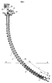
- FIG. 1 represents a drilled well 1 into which is introduced a pump 3 placed in an active position at the bottom of the well by a tubular conduit or column 2.
- the drilled well comprises near its surface a practically vertical zone extended downwards by a part deflected to become, at the bottom, strongly inclined in an area with a high content of withdrawable fluid.
- the present invention applies very particularly in the case of highly deviated wells, but it also retains all of its advantages in the case of vertical wells.
- the pump 3 fixed at the end of the column 2 is introduced from the surface and progresses into the well by the addition of tubular sections.
- a set of drive rods 30 placed end to end whose rotation is controlled by a drive head 23 connected to a motor 24 which may be of a type commonly used in pumping installations.
- the rotation of the rods 30 initiates the pumping device 3 which brings up the fluid circulating at the bottom of the well by the tubular column 2 to be evacuated towards the storage pipes 27.
- Valves 25 regulate the distribution of the pumped fluid on the surface.
- Pump 3 is introduced at the end of the column tubular 2 in a separation device 17 aimed at bringing the free gas suspended in the liquid to the surface, while the latter is sucked towards the bottom of the separation device at the inlet of the pump 3.
- the reference 31 designates a shutter device of the valve type.
- the lower end of the tubular column 2 at the bottom of the well is attached around its circumference to one end of an intermediate production tube 6.
- the other end of this intermediate tube is connected to the outlet of the pumping device.
- a "MOINEAU" type pump is used, but it is understood that the advantages of the present invention would apply equally favorably in the case of a piston pump, a centrifugal pump, or a pendulum pump.
- the "MOINEAU” pump 3 comprises a stator 4 provided with a tubular protective steel casing, covering an elastomer part or active part of the stator internally producing a helical gear.
- a set of rods 30 placed end to end is disposed inside the tubular column 2, passes through the intermediate production tube 6, and supports a rotor 5 so as to transmit to it a rotary movement controlled at the surface.
- This rotor 5 has on its surface a helical gear associated with the stator 4.
- the pump / intermediate production tube assembly is introduced into an intake duct 7, produced in the form of a tubular pipe open at its two ends.
- a first end is extended by a separation conduit 8 consisting of a tubular strainer provided with orifices 9 for introducing the fluid inside the conduit 7.
- the separation duct 8 and the intake duct 7 are connected to each other by a circular ring 15.
- the separation duct 8 is kept fixed around the intermediate production tube by a connecting member 16, this member comprising a threaded interior zone into which the upper end of the separation duct 8 is screwed.
- This member 16 also ensures coaxial maintenance and end-to-end positioning of the tubular column 2 and of the intermediate production tube 6.
- centering devices 10 are placed around these elements. These centering devices are, for example of the blade type, well known in drilling techniques soils. Other types of centralizers can also be used, for example rubber centralizers. These centralizers also have the advantage of limiting the oscillation movement of the pump along a section of the well.
- Stabilizers 11 of the aforementioned type are also placed around the intake duct 7 to place the assembly in the axis of the well.
- the lower end of the intake duct is provided with a closure device 31 comprising a part 20 providing a closure in which a valve is formed.
- This valve consists of a ball 21 constantly urged to block an opening for introducing fluid 23 by elastic means, such as, for example, a helical spring 22.
- the embodiment of Figure 3 avoids this risk.
- the device according to this embodiment comprises one or more valves arranged circumferentially on the lateral or cylindrical walls of the lower end of the intake duct, the requisite being to be below the intake level of the pump.
- the shutter system 32 shown in FIG. 3 comprises two shutter devices 33 and 34 positioned under the pump 3 and oriented in diametrically opposite directions.
- the closure devices 33 and 34 are superimposed relative to the axis of the intake duct 7.
- the operational safety of the obturation device is reinforced, since it suffices that one of the two obturation devices operates to ensure a continuous supply of fluid to the pump.
- the shutter device 33 comprises a shutter 35 having a conical bearing surface 36 which cooperates with a conical seat 37 secured to the intake duct at its lower end.
- the shutter 35 is guided by a cylindrical rod 38 which cooperates with a cylindrical housing 39 also carried by the intake duct 7.
- Return means 40 such as a helical spring surrounding the rod 38, applies the shutter 35 to its seat 37.
- the orientation of the conical surfaces of the shutter 35 and of the seat 37 is such that the shutter device prevents the flow of a fluid coming from inside the intake duct 7 and going towards the annular space 41 defined by the walls of the well and the external surface of the intake duct 7.
- the gas / liquid mixture rises in the well and meets the closure device which keeps the ball in blocking of the opening 23.
- the mixture progresses laterally around the intake duct 7 to the separation duct 8.
- the assembly pumping device has been lowered into the well, so that the dynamic level of the mixture (represented by line A in FIG. 1) is substantially above the separation pipe.
- the orifices regularly arranged around the duct of separation 8 allow the introduction of the fluid into the intake duct.
- a degassing phenomenon occurs at the level of the mixing surface; the gas escaping to the surface through the well and the fluid falling back into the intake duct.
- This pressure difference implies a force against the ball which moves away from its seat and allows the entry of the fluid / gas mixture directly through the lower end of the assembly.
- the pump is therefore constantly supplied with fluid. It then only remains to operate on the operating conduits, or reduce the speed of rotation and therefore the flow rate of the pump to promote an increase in the dynamic level at the height of the separation conduit 8.
- the pressures balance then between the outside and the inside of the intake duct 7, the ball comes to rest on its seat to block the opening and the separation phenomenon can again take place.
- This pressure balancing process is also carried out when the assembly is initially lowered and the intake duct 7 is empty of any fluid. In this state the pump is not yet running and when pressure balancing is completed, the pump is commissioned.
- This pressure difference implies a force against the shutter 35, which moves away from its seat 37 and allows the entry of the fluid / gas mixture directly through the lower end of the assembly.
- the pump is therefore constantly supplied with fluid.
- the intake duct 7 has a length L of practically 60 meters and the intermediate production tube 6 has a length of 45 approximately meters, the pump and a fluid reservoir then having a length 1 of 15 meters.
- the separation conduit 8 has a length of 1 meter.
- the length of the intake duct 7 can be adapted in the case of a different well orientation, so as to constantly achieve a pressure difference of a few bars between the intake level of the pump 3 and the level of the orifices. 9 of the separation duct.
- the present invention is particularly applicable in the case of highly deviated wells which can approach substantially the horizontal. However, it finds the same applications in the case of vertical wells.
Claims (8)
- Vorrichtung zur Trennung eines Gemisches aus freiem Gas und Flüssigkeit zur Beaufschlagung einer Pumpe (3), die mit einem unteren Ende einer röhrenförmigen Kolonne (2) am Boden eines gebohrten Bohrloches verbunden ist, wobei die Pumpe (3) mit der röhrenförmigen Kolonne (2) über ein Produktionszwischenrohr (6) verbunden ist und in eine Fluideinlaßvorrichtung (7, 8) eingeführt ist, von dem ein unteres Ende verschlossen ist, wobei das untere Ende wenigstens ein Ventil und ein oberes Ende Öffnungen (9) zum Einführen von Fluid aufweist, und die Pumpe im Inneren der Einlaßvorrichtung benachbart ihrem unteren Ende angeordnet ist, dadurch gekennzeichnet, daß diese Einlaßvorrichtung ein zylindrisches Rohr umfaßt und daß diese wenigstens ein Ventil (21, 22) bildende Vorrichtung auf den zylindrischen Wandungen dieser Einlaßvorrichtung angeordnet ist.
- Trennvorrichtung nach Anspruch 1, dadurch gekennzeichnet, daß diese Einlaßvorrichtung eine Einlaßleitung (7) umfaßt, welche koaxial das Produktionszwischenrohr (6) und die Pumpe (3) umschließt, wobei die Einlaßleitung verlängert über eine Trennleitung (8) ist, die über den Umfang mit Öffnungen (9) versehen und um diese röhrenförmige Kolonne (2) durch ein Befestigungsstück (16) gehalten ist.
- Trennvorrichtung nach Anspruch 2, dadurch gekennzeichnet, daß das Produktionszwischenrohr (16) und die Pumpe (3) koaxial zur Einlaßleitung über Zentrierstücke (10) gehalten sind.
- Trennvorrichtung nach Anspruch 1, dadurch gekennzeichnet, daß die wenigstens ein Ventil bildende Vorrichtung ein Verschlußglied, beispielsweise eine Kugel oder eine Klappe (21) umfaßt, die konstant durch elastische Mittel (22) zum Blockieren einer Einführungsöffnung (23) von Fluid in die Einlaßleitung beaufschlagt ist.
- Trennvorrichtung nach Anspruch 4, dadurch gekennzeichnet, daß die elastischen Mittel (22) einen Kompressionswiderstand bei Minimumdruck umfassen, wobei der Minimumdruck einem Flüssigkeitsniveau in der Einlaßleitung oberhalb der Pumpe entspricht.
- Trennvorrichtung nach einem der Ansprüche 1 bis 5, dadurch gekennzeichnet, daß die Einlaßleitung (7) und die Trennleitung (8) in dem gebohrten Loch durch Stabilisatoren (11) gehalten sind.
- Trennvorrichtung nach einem der Ansprüche 1 bis 6, dadurch gekennzeichnet, daß die Länge der Einlaßvorrichtung (7, 8) des Fluids derart gewählt wird, daß eine Druckdifferenz von etlichen bar zwischen dem Einlaßniveau der Pumpe (3) und dem Niveau der Einführungsöffnungen (9) des Fluids in diese Vorrichtung entwickelt wird.
- Pumpinstallation in einem Bohrloch mit einer Trennvorrichtung nach einem beliebigen der Ansprüche 1 bis 7, dadurch gekennzeichnet, daß dieses Bohrloch eine untere Zone umfaßt, deren Orientierung von der Vertikalen bis zu einer starken Neigung variiert.
Applications Claiming Priority (2)
| Application Number | Priority Date | Filing Date | Title |
|---|---|---|---|
| FR8917520A FR2656652B1 (fr) | 1989-12-28 | 1989-12-28 | Dispositif de separation d'un melange de gaz libre et de liquide a l'admission d'une pompe au fond d'un puits fore. |
| FR8917520 | 1989-12-28 |
Publications (2)
| Publication Number | Publication Date |
|---|---|
| EP0435716A1 EP0435716A1 (de) | 1991-07-03 |
| EP0435716B1 true EP0435716B1 (de) | 1994-10-05 |
Family
ID=9389198
Family Applications (1)
| Application Number | Title | Priority Date | Filing Date |
|---|---|---|---|
| EP90403476A Expired - Lifetime EP0435716B1 (de) | 1989-12-28 | 1990-12-06 | Vorrichtung zur Separation eines Gas-Flüssigkeitsgemisches als Zufuhr einer Imbohrlochpumpe |
Country Status (6)
| Country | Link |
|---|---|
| US (1) | US5113937A (de) |
| EP (1) | EP0435716B1 (de) |
| CA (1) | CA2033367A1 (de) |
| DK (1) | DK0435716T3 (de) |
| FR (1) | FR2656652B1 (de) |
| NO (1) | NO301848B1 (de) |
Families Citing this family (16)
| Publication number | Priority date | Publication date | Assignee | Title |
|---|---|---|---|---|
| FR2692320B1 (fr) * | 1992-06-12 | 1995-11-24 | Inst Francais Du Petrole | Dispositif et methode de pompage d'un liquide visqueux comportant l'injection d'un produit fluidifiant, application aux puits horizontaux. |
| FR2714120B1 (fr) * | 1993-12-16 | 1996-03-15 | Inst Francais Du Petrole | Systeme de pompage comportant une pompe volumetrique a grand debit |
| CA2120283C (en) * | 1994-03-30 | 2004-05-18 | Bernard Heinrichs | Down-hole gas separator |
| FR2727475B1 (fr) * | 1994-11-25 | 1997-01-24 | Inst Francais Du Petrole | Methode et systeme de pompage comportant une pompe volumetrique entrainee par un tube continu - application aux puits devies |
| FR2741382B1 (fr) * | 1995-11-21 | 1997-12-26 | Inst Francais Du Petrole | Methode et dispositif de production par pompage dans un drain horizontal |
| US6257333B1 (en) * | 1999-12-02 | 2001-07-10 | Camco International, Inc. | Reverse flow gas separator for progressing cavity submergible pumping systems |
| US6715556B2 (en) * | 2001-10-30 | 2004-04-06 | Baker Hughes Incorporated | Gas restrictor for horizontally oriented well pump |
| US6705402B2 (en) | 2002-04-17 | 2004-03-16 | Baker Hughes Incorporated | Gas separating intake for progressing cavity pumps |
| US7628209B2 (en) * | 2006-03-08 | 2009-12-08 | Baker Hughes Incorporated | Tubing driven progressing cavity pump and method of pumping well fluid from a well |
| US7971649B2 (en) | 2007-08-03 | 2011-07-05 | Pine Tree Gas, Llc | Flow control system having an isolation device for preventing gas interference during downhole liquid removal operations |
| CA2717366A1 (en) | 2008-03-13 | 2009-09-17 | Pine Tree Gas, Llc | Improved gas lift system |
| US7798211B2 (en) * | 2008-05-22 | 2010-09-21 | Baker Hughes Incorporated | Passive gas separator for progressing cavity pumps |
| WO2011073203A1 (en) * | 2009-12-14 | 2011-06-23 | Shell Internationale Research Maatschappij B.V. | Separating multiphase effluents of an underwater well |
| US8960273B2 (en) * | 2011-10-27 | 2015-02-24 | Oilfield Equipment Development Center Limited | Artificial lift system for well production |
| CN106150465B (zh) * | 2015-04-28 | 2018-12-11 | 中国石油化工股份有限公司 | 蒸汽驱油井井下注剂注入方法及装置 |
| US10260330B2 (en) | 2015-04-29 | 2019-04-16 | General Electric Company | Fluid intake for an artificial lift system and method of operating such system |
Family Cites Families (10)
| Publication number | Priority date | Publication date | Assignee | Title |
|---|---|---|---|---|
| US1573051A (en) * | 1925-06-17 | 1926-02-16 | Shell Company Of California | Gas anchor for pumping wells |
| US2267459A (en) * | 1939-01-09 | 1941-12-23 | Fmc Corp | Deep well pump |
| US2810352A (en) * | 1956-01-16 | 1957-10-22 | Eugene D Tumlison | Oil and gas separator for wells |
| US2969742A (en) * | 1958-07-18 | 1961-01-31 | Reda Pump Company | Gas separator for submergible motorpump assemblies |
| US3128719A (en) * | 1960-06-13 | 1964-04-14 | Shell Oil Co | Gas anchor |
| US4386654A (en) * | 1981-05-11 | 1983-06-07 | Becker John A | Hydraulically operated downhole oil well pump |
| US4592427A (en) * | 1984-06-19 | 1986-06-03 | Hughes Tool Company | Through tubing progressing cavity pump |
| US4664603A (en) * | 1984-07-31 | 1987-05-12 | Double R Petroleum Recovery, Inc. | Petroleum recovery jet pump pumping system |
| US4762176A (en) * | 1987-03-23 | 1988-08-09 | Miller Orand C | Air-water separator |
| FR2631379A1 (fr) * | 1988-05-11 | 1989-11-17 | Inst Francais Du Petrole | Dispositif de pompage d'un fluide au fond d'un puits fore notamment a zone basse fortement inclinee ou horizontale |
-
1989
- 1989-12-28 FR FR8917520A patent/FR2656652B1/fr not_active Expired - Fee Related
-
1990
- 1990-12-06 DK DK90403476.6T patent/DK0435716T3/da active
- 1990-12-06 EP EP90403476A patent/EP0435716B1/de not_active Expired - Lifetime
- 1990-12-21 NO NO905570A patent/NO301848B1/no not_active IP Right Cessation
- 1990-12-28 US US07/635,249 patent/US5113937A/en not_active Expired - Fee Related
- 1990-12-28 CA CA002033367A patent/CA2033367A1/fr not_active Abandoned
Also Published As
| Publication number | Publication date |
|---|---|
| FR2656652B1 (fr) | 1995-08-25 |
| FR2656652A1 (fr) | 1991-07-05 |
| NO905570D0 (no) | 1990-12-21 |
| EP0435716A1 (de) | 1991-07-03 |
| US5113937A (en) | 1992-05-19 |
| CA2033367A1 (fr) | 1991-06-29 |
| NO301848B1 (no) | 1997-12-15 |
| NO905570L (no) | 1991-07-01 |
| DK0435716T3 (da) | 1995-03-27 |
Similar Documents
| Publication | Publication Date | Title |
|---|---|---|
| EP0435716B1 (de) | Vorrichtung zur Separation eines Gas-Flüssigkeitsgemisches als Zufuhr einer Imbohrlochpumpe | |
| EP0013854A1 (de) | Sicherheitsverfahren und Vorrichtung für die unterirdische Lagerung von einem Fluidum unter Druck | |
| CA2204664C (fr) | Systeme de pompage polyphasique et centrifuge | |
| WO2004001180A1 (fr) | Conduite de guidage telescopique de forage en mer | |
| OA10434A (fr) | Procédé et installation de pompage d'un effluent pétrolier | |
| EP0187599A1 (de) | Druckmittelangetriebene Vorrichtung zum Messen und Ausführen von Arbeiten in einem abgelenkten Bohrloch während der Injektion oder der Förderung | |
| EP3283802B1 (de) | Vorrichtung zur steuerung der befüllung eines rohrs während des verlegens in einem gewässer und zugehörige anordnung und verfahren | |
| FR3018541A1 (fr) | Ancre de couple de blocage en rotation d'une colonne de production d'un puits, systeme de pompage et de blocage en rotation et installation de pompage equipee d'une telle ancre de couple | |
| EP0457879B1 (de) | Vorrichtung und verfahren zur reinigung eines unterirdischen bohrloches | |
| FR2652610A1 (fr) | Procede de pompage de melange liquide gaz dans un puits d'extraction petrolier et dispositif de mise en óoeuvre du procede. | |
| EP0192558A1 (de) | Vorrichtung zum Einordnen eines Werkzeugs oder Instruments in einem Rohr, insbesondere eine selbständige hydraulische Pumpe, die durch ein Steigrohr gewinnt | |
| CA2163711C (fr) | Methode et systeme de pompage comportant une pompe volumetrique entrainee par un tube continu - application aux puits devies | |
| WO2015082838A1 (fr) | Installation de betonnage et procede de betonnage correspondant | |
| FR2759113A1 (fr) | Installation de pompage d'un effluent biphasique liquide/gaz | |
| FR2503823A2 (fr) | Dispositif d'etancheite pour machine rotative a fluide hydraulique | |
| WO1996002732A1 (fr) | Ballon regulateur pour effluents polyphasiques et moyens de prelevements associes | |
| CA2822038C (fr) | Installation de pompage pour puits profond | |
| EP3334898B1 (de) | Unterwasseranlage zur gas-flüssigkeitstrennung | |
| FR2741382A1 (fr) | Methode et dispositif de production par pompage dans un drain horizontal | |
| FR2910049A1 (fr) | Systeme et methode de mesure dans un puits horizontal. | |
| CA2971753C (fr) | Dispositif d'evacuation de liquides accumules dans un puits | |
| EP0478421B1 (de) | Dichtungsvorrichtung mit eine Flüssigkeitsdichtung | |
| FR3017898A1 (fr) | Tete et procede d'aspiration de liquide dans un forage et/ou une cavite souterraine | |
| WO2011004125A1 (fr) | Dispositif de ressort à gaz avec système de lubrification dynamique | |
| EP3217054B1 (de) | Ablasseinrichtung und pumpe mit dieser einrichtung |
Legal Events
| Date | Code | Title | Description |
|---|---|---|---|
| PUAI | Public reference made under article 153(3) epc to a published international application that has entered the european phase |
Free format text: ORIGINAL CODE: 0009012 |
|
| 17P | Request for examination filed |
Effective date: 19901220 |
|
| AK | Designated contracting states |
Kind code of ref document: A1 Designated state(s): DK GB IT |
|
| 17Q | First examination report despatched |
Effective date: 19921208 |
|
| ITF | It: translation for a ep patent filed |
Owner name: MARIETTI E GISLON S.R.L. |
|
| GRAA | (expected) grant |
Free format text: ORIGINAL CODE: 0009210 |
|
| AK | Designated contracting states |
Kind code of ref document: B1 Designated state(s): DK GB IT |
|
| GBT | Gb: translation of ep patent filed (gb section 77(6)(a)/1977) |
Effective date: 19941026 |
|
| REG | Reference to a national code |
Ref country code: DK Ref legal event code: T3 |
|
| PLBE | No opposition filed within time limit |
Free format text: ORIGINAL CODE: 0009261 |
|
| STAA | Information on the status of an ep patent application or granted ep patent |
Free format text: STATUS: NO OPPOSITION FILED WITHIN TIME LIMIT |
|
| 26N | No opposition filed | ||
| PGFP | Annual fee paid to national office [announced via postgrant information from national office to epo] |
Ref country code: GB Payment date: 19991122 Year of fee payment: 10 |
|
| PGFP | Annual fee paid to national office [announced via postgrant information from national office to epo] |
Ref country code: DK Payment date: 19991217 Year of fee payment: 10 |
|
| PG25 | Lapsed in a contracting state [announced via postgrant information from national office to epo] |
Ref country code: DK Free format text: LAPSE BECAUSE OF NON-PAYMENT OF DUE FEES Effective date: 20001206 Ref country code: GB Free format text: LAPSE BECAUSE OF NON-PAYMENT OF DUE FEES Effective date: 20001206 |
|
| GBPC | Gb: european patent ceased through non-payment of renewal fee |
Effective date: 20001206 |
|
| REG | Reference to a national code |
Ref country code: DK Ref legal event code: EBP |
|
| PG25 | Lapsed in a contracting state [announced via postgrant information from national office to epo] |
Ref country code: IT Free format text: LAPSE BECAUSE OF NON-PAYMENT OF DUE FEES;WARNING: LAPSES OF ITALIAN PATENTS WITH EFFECTIVE DATE BEFORE 2007 MAY HAVE OCCURRED AT ANY TIME BEFORE 2007. THE CORRECT EFFECTIVE DATE MAY BE DIFFERENT FROM THE ONE RECORDED. Effective date: 20051206 |