EP0108000A1 - Anti-pivoting arrangement for a motor vehicle's power unit - Google Patents
Anti-pivoting arrangement for a motor vehicle's power unit Download PDFInfo
- Publication number
- EP0108000A1 EP0108000A1 EP83402016A EP83402016A EP0108000A1 EP 0108000 A1 EP0108000 A1 EP 0108000A1 EP 83402016 A EP83402016 A EP 83402016A EP 83402016 A EP83402016 A EP 83402016A EP 0108000 A1 EP0108000 A1 EP 0108000A1
- Authority
- EP
- European Patent Office
- Prior art keywords
- support
- stop
- spring
- fixed
- support element
- Prior art date
- Legal status (The legal status is an assumption and is not a legal conclusion. Google has not performed a legal analysis and makes no representation as to the accuracy of the status listed.)
- Granted
Links
- 230000036316 preload Effects 0.000 claims description 2
- 125000006850 spacer group Chemical group 0.000 claims 1
- 230000005540 biological transmission Effects 0.000 abstract description 2
- 230000008878 coupling Effects 0.000 description 3
- 238000010168 coupling process Methods 0.000 description 3
- 238000005859 coupling reaction Methods 0.000 description 3
- 238000010586 diagram Methods 0.000 description 3
- 239000012530 fluid Substances 0.000 description 3
- 230000001970 hydrokinetic effect Effects 0.000 description 3
- 230000007935 neutral effect Effects 0.000 description 3
- 230000010355 oscillation Effects 0.000 description 3
- 230000003042 antagnostic effect Effects 0.000 description 2
- 238000002485 combustion reaction Methods 0.000 description 2
- 238000006073 displacement reaction Methods 0.000 description 2
- 230000003068 static effect Effects 0.000 description 2
- 239000000725 suspension Substances 0.000 description 2
- 238000013459 approach Methods 0.000 description 1
- 238000006243 chemical reaction Methods 0.000 description 1
- 230000007423 decrease Effects 0.000 description 1
- 238000001914 filtration Methods 0.000 description 1
- 238000005096 rolling process Methods 0.000 description 1
Images

Classifications
-
- B—PERFORMING OPERATIONS; TRANSPORTING
- B60—VEHICLES IN GENERAL
- B60K—ARRANGEMENT OR MOUNTING OF PROPULSION UNITS OR OF TRANSMISSIONS IN VEHICLES; ARRANGEMENT OR MOUNTING OF PLURAL DIVERSE PRIME-MOVERS IN VEHICLES; AUXILIARY DRIVES FOR VEHICLES; INSTRUMENTATION OR DASHBOARDS FOR VEHICLES; ARRANGEMENTS IN CONNECTION WITH COOLING, AIR INTAKE, GAS EXHAUST OR FUEL SUPPLY OF PROPULSION UNITS IN VEHICLES
- B60K5/00—Arrangement or mounting of internal-combustion or jet-propulsion units
- B60K5/12—Arrangement of engine supports
- B60K5/1241—Link-type support
-
- B—PERFORMING OPERATIONS; TRANSPORTING
- B60—VEHICLES IN GENERAL
- B60K—ARRANGEMENT OR MOUNTING OF PROPULSION UNITS OR OF TRANSMISSIONS IN VEHICLES; ARRANGEMENT OR MOUNTING OF PLURAL DIVERSE PRIME-MOVERS IN VEHICLES; AUXILIARY DRIVES FOR VEHICLES; INSTRUMENTATION OR DASHBOARDS FOR VEHICLES; ARRANGEMENTS IN CONNECTION WITH COOLING, AIR INTAKE, GAS EXHAUST OR FUEL SUPPLY OF PROPULSION UNITS IN VEHICLES
- B60K5/00—Arrangement or mounting of internal-combustion or jet-propulsion units
- B60K5/12—Arrangement of engine supports
- B60K5/1291—Supports comprising stoppers
Definitions
- the present invention relates to an anti-tilt device for a motor-propulsion unit of a motor vehicle suspended elastically from the structure of the vehicle.
- this type of device comprises a stop of low flexibility interposed with a small spacing in a direction perpendicular to the axis of rotation of the powertrain, between support elements linked respectively to the group and to the structure .
- the invention applies very particularly to a powertrain comprising a hydrokinetic coupler, a gearbox and an output shaft with an axis parallel to the axis of rotation of the engine.
- the elastic suspension of a powertrain on the structure of a motor vehicle generally comprises, in addition to supports receiving the static load of this group, a device with one or more stops which limits its tilting around a parallel axis to its output tree. This tilting tends to occur in one direction or the other depending on whether the torque exerted by the group on the output shaft is directed in the direction corresponding to the forward or reverse movement of the vehicle. This is why the anti-tilt device comprises at least one forward travel stop and one reverse travel stop.
- the object of the invention is to obtain the same result by simpler means and therefore less expensive, in particular by avoiding the use of. a pressurized fluid.
- the anti-tilt device targeted by the invention comprises reverse and forward stops, of low flexibility, interposed in a direction perpendicular to the axis of rotation of the group, each between two support elements, one of which is linked to a support that is part of the powertrain, and the other to a support that is part of the structure.
- one of the support elements of at least one of the stops is mounted movable relative to its support, and kept spaced from the latter by a determined distance, in a direction perpendicular to the axis of rotation of the group, by means of a pre-stressed elastic member of great flexibility, one end of which is integral with the support with respect to which said support element is movably mounted.
- the pre-stressed elastic member exerts on the stop a force antagonistic to that resulting from the tilting of the powertrain, this opposing force being slightly less than the force supported by the stop, so that the aforementioned distance or play is not caught. Under these conditions, the vibrations of the group are filtered by the elastic member of great flexibility and are therefore not transmitted to the structure of the vehicle.
- one of the stops for example the forward stop, is fixed on a support element integral with a screw passing through the support and which is elastically urged towards the opposite support element of the stop by a pre-stressed spring constituting said elastic member , for example at. blade, one end of which is fixed to the structure and tends to normally maintain the support element separated from the support by a distance equal to the aforementioned distance.
- elastic studs are fixed on the face of the support element of the stopper facing the support, with between these studs and said member the distance or clearance mentioned above, and a nut as well as an elastic piece such as a washer are interposed between the spring and the support, so that the nut remains applied against the washer by the prestressed spring, as long as the tilting force supported by the stop is less than the antagonistic spring preload force.
- the highly flexible prestressed elastic member is a leaf spring folded in the shape of a hairpin, one branch of which is fixed to one of the supports and the other branch of which constitutes an element of support of one of the stops, for example the forward stop, and a bracing member ensures the bringing together of the two branches of the spring in order to create the prestress, said support element being maintained at a predetermined distance from its support.
- the support on which the spring is fixed is the support forming part of the power train.
- a powertrain 1 comprising an internal combustion engine with reciprocating pistons, connected by a delivery device hydrokinetic coupling such as a torque converter, to an automatic gearbox whose output shaft 2 is substantially parallel to the axis 3 of rotation of the engine crankshaft.
- This power unit can in particular be a diesel engine fitted to a front-wheel drive vehicle, this group being mounted transversely to the direction of advance F of the vehicle.
- the wedge 7 rests on the bottom of a support 16 forming part of the structure 5, to which it is fixed by threaded rods and such nuts. as the rod 27 and the nut 28.
- the lower part of the group 1 is connected to the structure 5, in a manner known per se, by a link 8 and two elastic joints 9, 10.
- a stop 11 for the rear market On either side of the support 6, and in a horizontal direction X-X orthogonal to the axis 3, are arranged two anti-tilting stops, namely a stop 11 for the rear market, and a stop 12 for forward travel.
- the reverse stop 11 is fixed in a known manner to a support element 13 secured to a screw 14 allowing its fixing by a nut 15 on the support 16 forming part of the structure 5.
- the stop 11 is arranged at a low distance e l of a support element 17 belonging to the support 6.
- the abutment 12 of forward is attached to a support member 18 secured to a 'v is 19 which passes through the support 16 and a pretensioned elastic element, constituted in this example by a leaf spring 20, on which it is fixed between two nuts 21,22.
- the spring 20 is fixed by its end opposite to the screw 19, on a part 29 of the structure 5, by means of a bolt system 23 - nut 31.
- the spring 20 has great flexibility and is mounted prestressed, so as to press the nut 21 against an elastic washer 24 fixed on the support 16, coaxially with the screw 19.
- elastic studs 25 are fixed on the face of the support element 18 of the stopper 12 facing the support 16, so that between these studs 25 and the support 16. J, measured in the direction XX, as long as the nut 21 remains applied against the washer 24 by the spring 20. Furthermore, a clearance e 2 appears between the stop 12 and a support element 26 belonging to the support 6.
- the support element 18 of the forward travel stop 12 is mounted movable relative to its support 16, and kept spaced therefrom. the predetermined distance J in a direction perpendicular to. the axis of rotation 3 of group 1, by means of the pre-stressed spring 20 of great flexibility.
- the hydraulic coupler When the gearbox is engaged in a forward gear, the hydraulic coupler permanently ensures the coupling, by sliding of fluid, between the engine and the gearbox. Group 1 therefore transmits on the output shaft 2, as long as the vehicle is stopped, a drag torque which tends to move the vehicle forward. By reaction, the group 1 tends to tilt in the opposite direction and the support element 26 comes to bear on the stop 12.
- the prestressing force exerted by the spring 20 being slightly less than the force supported by the stop 12, under the above conditions, the nut 21 is moved away from the washer 24 without however the clearance J being caught up.
- the vibrations of group 1 are then filtered by the spring 20 of great flexibility.
- the elastic studs 25 come to bear on the support 16 because the prestressing force of the spring 20 becomes less than the force transmitted to the stop 12 by the support 6.
- the stop 12 then stops the tilting of the powertrain 1 in the usual way.
- FIG. 3 illustrates this operation, using a numerical example.
- curve A represents the force / displacement law along the X-X axis, the force being on the ordinate and the displacement (in mm) on the abscissa.
- the stiffness is very low; this stiffness is that of the spring 20, that is to say 6 daN / mm.
- the stiffness becomes very strong because it is that of the stop 12 proper.
- the anti-tilt device makes it possible to produce an anti-tilt stop which has great flexibility in the load zone corresponding to the drag torque at idle, without having the disadvantage of a high clearance for this. charge.
- the second embodiment, illustrated in Figures 4 and 5 comprises a support 30 secured to a power unit not shown fixed by a nut 60 on a screw 32 secured to an elastic wedge 33 itself fixed, in the usual way on a support 34 belonging to the structure of the vehicle.
- two anti-tilting stops are arranged, namely a stop 35 for reverse gear and a stop 36 for forward gear.
- the reverse stop 35 is fixed in a known manner to a support element 37 integral with a screw 38 allowing its fixing, by a nut 39, on the support 34.
- An adjustment shim 40 interposed between the element d the support 37 and the support 34 makes it possible to adjust the distance between the stop 35 and a support element 41 belonging to the support 30 to a predetermined value e 1 .
- the forward stop 36 is fixed on a support element 42 integral with a screw 4 allowing its fixing, by a nut 44, on the support 34.
- An adjustment shim 45 interposed between the support element 42 and the support 34, allows d 'adjust to a predetermined value e 2 the distance between the stop 36 of a support element 46.
- the latter consists of a branch of a leaf spring 47 folded in the shape of a hairpin.
- the second branch 48 of this leaf spring is fixed to the support 30 by means of the nut 31.
- the two chambers 46, 48 of the spring 47 are connected by a bracing member 49 which freely crosses the support 30, in a bore 50 ( Figure 4).
- the member 49 shown in detail in FIG. 4 comprises a sleeve 51 fixed to the branch 46 by a rivet 52. This sleeve freely crosses the branch 48, through an orifice 53, and has a stop shoulder 54 held in abutment against this branch 48 by the elasticity of the spring 47. In this position, a clearance J is formed between the branch 46 constituting a support element for the stop 36 and the support 30.
Landscapes
- Engineering & Computer Science (AREA)
- Chemical & Material Sciences (AREA)
- Combustion & Propulsion (AREA)
- Transportation (AREA)
- Mechanical Engineering (AREA)
- Vibration Prevention Devices (AREA)
- Motor Power Transmission Devices (AREA)
- Retarders (AREA)
Abstract
Dispositif anti-basculement pour un groupe motopropulseur (1) de véhicule automobile, suspensu élastiquement à la structure (5) du véhicule, comprenant des butées (11,12) de marche arrière et de marche avant de faible flexibilité, interposées chacune entre deux éléments d'appui dont l'un est lié au support (6) du groupe (1) et l'autre à un support (16) faisant partie de la structure (5). L'un (18) des éléments d'appui d'au moins une (12) des butées est monté mobile par rapport à son support (16) et maintenu écarté de celui-ci d'une distance prédéterminée (J) dans une direction perpendiculaire à l'axe de rotation du groupe (1), au moyen d'un ressort précontraint (20) de grande flexibilité. Cet agencement permet, lorsque la boîte de vitesses est sur un rapport de marche avant et que le véhicule reste arrêté, d'empêcher la transmission à la structure (5) des vibrations du groupe (1) par la butée (12) de marche avant.Anti-tilting device for a motor vehicle powertrain (1), resiliently suspended from the structure (5) of the vehicle, comprising low flexibility reverse and forward stops, each interposed between two elements support one of which is linked to the support (6) of the group (1) and the other to a support (16) forming part of the structure (5). One (18) of the support elements of at least one (12) of the stops is mounted movable relative to its support (16) and kept spaced therefrom by a predetermined distance (J) in a direction perpendicular to the axis of rotation of the group (1), by means of a pre-stressed spring (20) of great flexibility. This arrangement makes it possible, when the gearbox is in a forward gear and the vehicle remains stopped, to prevent the transmission to the structure (5) of the vibrations of the group (1) by the forward stop (12). .
Description
La présente invention a pour objet un dispositif anti-basculement pour un groupe moto-propulseur de véhicule automobile suspendu élastiquement à la structure du véhicule.The present invention relates to an anti-tilt device for a motor-propulsion unit of a motor vehicle suspended elastically from the structure of the vehicle.
Comme on le sait, ce genre de dispositif comprend une butée de faible flexibilité interposée avec un faible espacement suivant une direction perpendiculaire à l'axe de rotation du groupe moto-propulseur, entre des éléments d'appui liés respectivement au groupe et à la structure.As is known, this type of device comprises a stop of low flexibility interposed with a small spacing in a direction perpendicular to the axis of rotation of the powertrain, between support elements linked respectively to the group and to the structure .
L'invention s'applique tout particulièrement à un groupe moto-propulseur comprenant un coupleur hydrocinétique, une boîte de vitesses et un arbre de sortie d'axe parallèle à l'axe de rotation du moteur.The invention applies very particularly to a powertrain comprising a hydrokinetic coupler, a gearbox and an output shaft with an axis parallel to the axis of rotation of the engine.
La suspension élastique d'un groupe moto-propulseur sur la structure d'un véhicule automobile comporte généralement, en plus de supports recevant la charge statique de ce groupe, un dispositif à une ou plusieurs butées qui limite son basculement autour d'un axe parallèle à son arbre de sortie. Ce basculement tend à se produire dans un sens ou dans l'autre selon que le couple exercé par le groupe sur l'arbre de sortie est dirigé dans le sens correspondant à la marche avant ou à la marche arrière du véhicule. C'est pourquoi le dispositif anti-basculement comporte au moins une butée de marche avant et une butée de marche arrière.The elastic suspension of a powertrain on the structure of a motor vehicle generally comprises, in addition to supports receiving the static load of this group, a device with one or more stops which limits its tilting around a parallel axis to its output tree. This tilting tends to occur in one direction or the other depending on whether the torque exerted by the group on the output shaft is directed in the direction corresponding to the forward or reverse movement of the vehicle. This is why the anti-tilt device comprises at least one forward travel stop and one reverse travel stop.
Lorsque l'arbre de sortie est coaxial ou parallèle à l'axe de rotation du moteur, notamment à l'axe du vilebre- quindans le cas d'un moteur à combustion interne à pistons alternatifs, les éventuelles vibrations angulaires du moteur autour de son axe sont susceptibles d'être transmises à la structure du véhicule par ces butées. Pour éviter cet inconvénient, qui en pratique n'est sensible que lorsque le moteur tourne au ralenti, il est habituel d'espacer légèrement chacune de ces butées de l'un des éléments d'appui liés,respectivement, au groupe et à la structure, et entre lesquels elle est interposée. De cette façon, lorsqu'aucun couple n'est transmis par le groupe à l'arbre de sortie, en particulier parce que la boîte de vitesses est en position "neutre" ou "point mort", ou parce qu'un dispositif que comporte le groupe est débrayé, les faibles oscillations angulaires du groupe, dues aux vibrations du moteur,s'effectuent sans intervention des butées, donc sans transmission de vibrations à la structure.When the output shaft is coaxial or parallel to the axis of rotation of the engine, in particular to the axis of the crankshaft, in the case of an internal combustion engine with reciprocating pistons, any angular vibrations of the engine around its axis are likely to be transmitted to the vehicle structure by these stops. To avoid this drawback, which in practice is only noticeable when the engine is idling, it is usual to space each of these stops slightly from one of the elements support linked, respectively, to the group and the structure, and between which it is interposed. In this way, when no torque is transmitted by the group to the output shaft, in particular because the gearbox is in the "neutral" or "neutral" position, or because a device that includes the group is disengaged, the small angular oscillations of the group, due to the vibrations of the motor, are carried out without intervention of the stops, therefore without transmission of vibrations to the structure.
Cependant, lorsque le dispositif d'accouplement est du type hydrocinétique, un certain couple de traînée est transmis en permanence du moteur à la boîte de vitesses. Ainsi, lorsque le véhicule est à l'arrêt, moteur tournant au ralenti, donc susceptible de vibrer, et la boîte de vitesses engagée sur un rapport de marche avant ou arrière, comme c'est le cas fréquemment en circulation urbaine, le couple de traînée tend à faire basculer le groupe dans un sens, provoquant la mise en contact de la butée correspondante. Celle-ci transmet alors à la structure les vibrations du moteur avec un filtrage insuffisant, car elle possède une faible flexibilité pour pouvoir s'opposer efficacement au basculement du groupe lors des fortes charges appliquées au moteur.However, when the coupling device is of the hydrokinetic type, a certain drag torque is continuously transmitted from the engine to the gearbox. Thus, when the vehicle is stationary, the engine idling, therefore likely to vibrate, and the gearbox engaged in a forward or reverse gear, as is frequently the case in urban traffic, the torque of drag tends to tilt the group in one direction, causing the corresponding stop to come into contact. This then transmits the vibrations of the engine to the structure with insufficient filtering, because it has low flexibility to be able to effectively oppose the group tilting during heavy loads applied to the engine.
Dans la demande de brevet français publiée sous le n° 2 487 740, il a déjà été proposé, pour résoudre ce problème, une solution dans laquelle, à la butée normale anti-basculement, est associée une butée auxiliaire de grande flexibilité comprenant une chambre extensible reliée à une source de fluide sous pression, au moins lorsque le moteur est au ralenti avec un rapport de marche engagé dans la boite de vitesses.In the French patent application published under No. 2,487,740, a solution has already been proposed to solve this problem in which, with the normal anti-tilting stop, is associated an auxiliary stop of great flexibility comprising a chamber extensible connected to a source of pressurized fluid, at least when the engine is idling with a gear ratio engaged in the gearbox.
L'invention a pour but d'obtenir le même résultat par des moyens plus simples et par conséquent moins onéreux, en évitant notamment le recours à. un fluide sous pression.The object of the invention is to obtain the same result by simpler means and therefore less expensive, in particular by avoiding the use of. a pressurized fluid.
Le dispositif anti-basculement visé par l'invention comprend des butées de marche arrière et de marche avant, de faible flexibilité, interposées dans une direction perpendiculaire à l'axe de rotation du groupe, chacune entre deux éléments d'appui dont l'un est lié à un support faisant partie du groupe moto-propulseur, et l'autre à un support faisant partie de la structure.The anti-tilt device targeted by the invention comprises reverse and forward stops, of low flexibility, interposed in a direction perpendicular to the axis of rotation of the group, each between two support elements, one of which is linked to a support that is part of the powertrain, and the other to a support that is part of the structure.
Conformément à l'invention, l'un des éléments d'appui d'au moins une des butées est monté mobile par rapport à son support, et maintenu écarté de celui-ci d'une distance déterminée, dans une direction perpendiculaire à l'axe de rotation du groupe, au moyen d'un organe élastique précontraint de grande flexibilité dont une extrémité est solidaire du support par rapport auquel ledit élément d'appui est monté mobile.According to the invention, one of the support elements of at least one of the stops is mounted movable relative to its support, and kept spaced from the latter by a determined distance, in a direction perpendicular to the axis of rotation of the group, by means of a pre-stressed elastic member of great flexibility, one end of which is integral with the support with respect to which said support element is movably mounted.
De ce fait, si l'élément d'appui de la butée de marche avant est mobile par rapport à son support et maintenu écarté de celui-ci par l'organe élastique précontraint, et que la boîte de vitesses est engagée sur un rapport de marche avant, l'organe élastique précontraint exerce sur la butée une force antagoniste à celle résultant du basculement du groupe moto-propulseur, cette force antagoniste étant légèrement inférieure à l'effort supporté par la butée, de telle sorte que la distance ou jeu précité ne soit pas rattrapé. Dans ces conditions, les vibrations du groupe sont filtrées par l'organe élastique de grande flexibilité et ne sont donc pas transmises a la structure du véhicule.Therefore, if the support element of the forward stop is movable relative to its support and kept spaced therefrom by the pre-stressed elastic member, and the gearbox is engaged on a gear ratio forward, the pre-stressed elastic member exerts on the stop a force antagonistic to that resulting from the tilting of the powertrain, this opposing force being slightly less than the force supported by the stop, so that the aforementioned distance or play is not caught. Under these conditions, the vibrations of the group are filtered by the elastic member of great flexibility and are therefore not transmitted to the structure of the vehicle.
Suivant une forme de réalisation de l'invention, dans laquelle le groupe moto-propulseur est suspendu à un support placé en appui sur une cale élastique de grande flexibilité, supportée par la structure, l'une des butées, par exemple la butée de marche avant, est fixée sur un élément d'appui solidaire d'une vis traversant le support et qui est éslastiquement sollicitée vers l'élément d'appui opposé de la butée par un ressort précontraint constituant ledit organe élastique, par exemple à. lame, dont une extrémité est fixée à la structure et tend à maintenir normalement l'élément d'appui écarté du support d'une distance égale à la distance précitée.According to one embodiment of the invention, in which the powertrain is suspended from a support placed in abutment on an elastic block of great flexibility, supported by the structure, one of the stops, for example the forward stop, is fixed on a support element integral with a screw passing through the support and which is elastically urged towards the opposite support element of the stop by a pre-stressed spring constituting said elastic member , for example at. blade, one end of which is fixed to the structure and tends to normally maintain the support element separated from the support by a distance equal to the aforementioned distance.
Ainsi, lorsque la boite de vitesses est sur un rapport de marche avant et que par conséquent le support du groupe moto-propulseur bascule et exerce un effort sur la butée, celle-ci se rapproche de son support faisant partie de la structure, de sorte que le jeu diminue mais n'est pas annulé, tant que le véhicule est arrêté. La lame élastique constituant le ressort précontraint s'oppose en effet à ce que la butée vienne en appui sur son support.Thus, when the gearbox is on a forward gear and consequently the support of the powertrain rocker and exerts a force on the stop, the latter approaches its support forming part of the structure, so the game decreases but is not canceled, as long as the vehicle is stopped. The elastic blade constituting the prestressed spring in fact prevents the stop coming to bear on its support.
Suivant une particularité de l'invention, des plots élastiques sont fixés sur la face de l'élément d'appui de la butée tournée vers le support , avec entre ces plots et ledit organe la distance ou jeu précité, et un écrou ainsi qu'une pièce élastique telle qu'une rondelle sont interposés entre le ressort et le support , de manière que .'l'écrou reste appliqué contre la rondelle par le ressort précontraint,tant que l'effort de basculement supporté par la butée est inférieur à la force de précontrainte antagoniste du ressort.According to a feature of the invention, elastic studs are fixed on the face of the support element of the stopper facing the support, with between these studs and said member the distance or clearance mentioned above, and a nut as well as an elastic piece such as a washer are interposed between the spring and the support, so that the nut remains applied against the washer by the prestressed spring, as long as the tilting force supported by the stop is less than the antagonistic spring preload force.
Lorsque les couples exercés sur la butée par le basculement du groupe moto-propulseur deviennent plus importants, au cours du roulement du véhicule, les plots élastiques viennent alors en appui .sur le support de la butée, qui stoppe le basculement du groupe moto-propulseur de la façon habituelle.When the torques exerted on the stop by the tilting of the powertrain become greater, during the running of the vehicle, the elastic studs then come to bear on the support of the stop, which stops the tilting of the powertrain in the usual way.
Suivant une forme de réalisation avantageuse, l'organe élastique précontraint de grande flexibilité est un ressort à lame repliée en forme d'épingle à cheveux, dont une branche est fixée sur l'un des supports et dont l'autre branche constitue un élément d'appui de l'une des butées, par exemple la butée de marche avant, et un organe d'entretoisement assure le rapprochement des deux branches du ressort afin de créer la précontrainte, ledit élément d'appui étant maintenu à une distance prédéterminée de son support.According to an advantageous embodiment, the highly flexible prestressed elastic member is a leaf spring folded in the shape of a hairpin, one branch of which is fixed to one of the supports and the other branch of which constitutes an element of support of one of the stops, for example the forward stop, and a bracing member ensures the bringing together of the two branches of the spring in order to create the prestress, said support element being maintained at a predetermined distance from its support.
De préférence, le support sur lequel est fixé le ressort est le support faisant partie du groupe moto-propulseur.Preferably, the support on which the spring is fixed is the support forming part of the power train.
D'autres particularités et avantages de l'invention apparaîtront au cours de la description qui va suivre, faite en référence aux dessins annexés qui en illustrent deux exemples de réalisation non limitatifs.
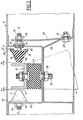
- La Figure 1 estune vue schématique en élévation latérale d'un groupe moto-propulseur équipé d'un dispositif anti-basculement selon l'invention.
- La Figure 2 est me vue mi-coupe mi-élévation à échelle agrandie du dispositif anti-basculement de la Figure 1.
- La Figure 3 est un diagramme illustrant le fonctionnement du dispositif anti-basculement.
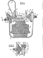
- La Figure 4 est une vue en élévation, avec coupe partielle d'un second mode de réalisation du dispositif selon l'invention.
- La Figure 5 est une section selon la ligne V-V de la Figure 4.
- Figure 1 is a schematic side elevation view of a powertrain equipped with an anti-tilt device according to the invention.
- FIG. 2 is a half-sectional mid-elevation view on an enlarged scale of the anti-tilting device of FIG. 1.
- Figure 3 is a diagram illustrating the operation of the anti-tip device.
- Figure 4 is an elevational view, partially in section, of a second embodiment of the device according to the invention.
- Figure 5 is a section along line VV in Figure 4.
On voit schématiquement à la Figure 1 un groupe moto-propulseur 1 comprenant un moteur à combustion interne à pistons alternatifs, relié par un dispositif d'accouplement hydrocinétique tel qu'un convertisseur de couple, à une boîte de vitesses automatique dont l'arbre de sortie 2 est sensiblement parallèle à l'axe 3 de rotation du vilebrequin du moteur.We see schematically in Figure 1 a
Ce groupe moto-propulseur peut être notamment à moteur diesel équipant un véhicule à traction avant, ce groupe étant monté transversalement par rapport à la direction d'avancement F du véhicule.This power unit can in particular be a diesel engine fitted to a front-wheel drive vehicle, this group being mounted transversely to the direction of advance F of the vehicle.
Une console 4, fixée à la partie supérieure du groupe moto-propulseur 1, transmet la charge statique de ce dernier à la structure 5 du véhicule, par l'intermédiaire d'un support 6 et d'une cale élastique 7 de grande flexibilité suivant une direction horizontale orthogonale à l'axe 3. La cale 7 repose sur le fond d'un support 16 faisant partie de la structure 5, auquel elle est fixée par des tiges filetées et des écrous tels. que la tige 27 et l'écrou 28. La partie inférieure du groupe 1 est reliée à la structure 5, de façon connue en soi, par une biellette 8 et deux articulations élastiques 9,10.A console 4, fixed to the upper part of the
De part et d'autre du support 6, et suivant une direction horizontale X-X orthogonale à l'axe 3, sont disposées deux butées anti-basculement, à savoir une butée 11 pour la marché arrière, et une butée 12 pour la marche avant.On either side of the
La butée 11 de marche arrière est fixée de manière connue sur un élément d'appui 13 solidaire d'une vis 14 permettant sa fixation par un écrou 15 sur le support 16 faisant partie de la structure 5. La butée 11 est disposée à une faible distance el d'un élément d'appui 17 appartenant au support 6.The
La butée 12 de marche avant est fixée sur un élément d'appui 18 solidaire d'une 'vis 19 qui traverse le support 16 ainsi qu'un organe élastique précontraint, constitué dans cet exemple par un ressort à lame 20, sur lequel elle est fixée entre deux écrous 21,22. Le ressort 20 est fixé par son extrémité opposée à la vis 19, sur une partie 29 de la structure 5, au moyen d'un système boulon 23 - écrou 31. Le ressort 20 présente une grande flexibilité et est monté précontraint, de manière à plaquer l'écrou 21 contre une rondelle élastique 24 fixée sur le support 16, coaxialement à la vis 19.The
D'autre part, des plots élastiques 25 sont fixés sur la face de l'élément d'appui 18 de la butée 12 tournée vers le support 16 , de façon qu'entre ces plots- 25 et le support 16 .soit réservé un jeu J, mesuré suivant la direction X-X,tant que l'écrou 21 reste appliqué contre la rondelle 24 par le ressort 20. Par ailleurs, un jeu e2 apparaît entre la butée 12 et un élément d'appui 26 appartenant au support 6.On the other hand,
Ainsi, dans cet exemple de réalisation du dispositif anti-basculement visé par l'invention, l'élément d'appui 18 de la butée de marche avant 12 est monté mobile par rapport à son support 16 , et maintenu écarté de celui-ci de la distance prédéterminée J dans une direction perpendiculaire à. l'axe de rotation 3 du groupe 1, et ce au moyen du ressort précontraint 20 de grande flexibilité.Thus, in this embodiment of the anti-tilt device targeted by the invention, the
Le fonctionnement du dispositif anti-basculement qui vient d'être décrit est le suivant:
- Lorsque la boîte de vitesses est en position "neutre", le groupe moto-
propulseur 1 ne transmet aucun couple sur l'arbre desortie 2. Celui-ci ne tend donc pas à basculer, et les jeux el, e2 lui permettent d'osciller librement, avec une très faible amplitude, sans mise en contact des éléments d'appui 17 ou 26 avec, respectivement, lesbutées 11 ou 12. De cette façon, les vibrations du moteur, convenablement filtrées par la cale porteuse 7, ne sont pas transmises à lastructure 5, notamment au ralenti.
- When the gearbox is in the "neutral" position, the
powertrain 1 does not transmit any torque to theoutput shaft 2. The latter therefore does not tend to tilt, and the games e l , e 2 allow it to oscillate freely, with a very small amplitude, without bringing thesupport elements 17 or 26 into contact with, respectively, thestops support wedge 7, are not transmitted tostructure 5, in particular at idle.
Lorsque la boîte de vitesses est engagée sur un rapport de marche avant, le coupleur hydraulique assure en permanence l'accouplement, par glissement de fluide, entre le moteur et la boîte de vitesses. Le groupe 1 transmet donc sur l'arbre de sortie 2, tant que le véhicule est arrêté, un couple de traînée qui tend à faire avancer le véhicule. Par réaction, le groupe 1 tend à basculer en sens inverse et l'élément d'appui 26 vient porter sur la butée 12.When the gearbox is engaged in a forward gear, the hydraulic coupler permanently ensures the coupling, by sliding of fluid, between the engine and the gearbox.
La force de précontrainte exercée par le ressort 20 étant légèrement inférieure à l'effort supporté par la butée 12, dans les conditions ci-dessus, l'écrou 21 est écarté de la rondelle 24 sans toutefois que le jeu J soit rattrapé. Les vibrations du groupe 1 sont alors filtrées par le ressort 20 de grande flexibilité.The prestressing force exerted by the
Pour des couples plus importants, rencontrés au cours du roulement, les plots élastiques 25 viennent en appui sur le support 16 du fait que la force de précontrainte du ressort 20 devient inférieure à l'effort transmis à la butée 12 par le support 6. La butée 12 stoppe alors le basculement du groupe moto-propulseur 1 de la façon habituelle.For larger torques, encountered during rolling, the
Le diagramme de la Fig.3 permet d'illustrer ce fonctionnement, au moyen d'un exemple numérique.The diagram in Fig. 3 illustrates this operation, using a numerical example.
Sur ce diagramme, la courbe A représente la loi force/déplacement suivant l'axe X-X, la force étant en ordonnées et le déplacement (en mm) en abscisses. Dans sa première partie, correspondant au rattrapage du jeu J, soit 3,4 mm , la raideur est très faible; cette raideur est celle du ressort 20, soit 6 daN/mm. Lorsque le jeu J est rattrapé, la raideur devient très forte du fait que c'est celle de la butée 12 proprement dite.On this diagram, curve A represents the force / displacement law along the X-X axis, the force being on the ordinate and the displacement (in mm) on the abscissa. In its first part, corresponding to the backlash J, ie 3.4 mm, the stiffness is very low; this stiffness is that of the
L'effort de précontrainte du ressort 20 est de 50 daN. Le moteur tournant au ralenti et un rapport de marche avant étant engagé dans la boite de vitesses, l'effort exercé par le groupe moto-propulseur 1 sur la butée 12 est 60 daN. Dans ces conditions, on voit que la déflexion moyenne au droit de la butée 12 est d'environ 1,7 mm. Si l'on voulait, avec une butée élastique classique, avoir la même raideur de 6 daN/mm pour le même effort de 60 daN, on aurait une déflexion de 10 mm (courbe B). Ceci présenterait alors les inconvénients suivants:
- - oscillations longitudinales gênantes lors des inversions de couple;
- - contraintes élevées sur la
cale porteuse 7; - - risques accrus de contact entre groupe moto-propulseur
let structure 5.
- - annoying longitudinal oscillations during torque reversals;
- - high stresses on the supporting
wedge 7; - - increased risks of contact between powertrain and
structure 5.
Par conséquent, le dispositif anti-basculement selon l'invention permet de réaliser une butée anti-basculement qui possède une grande flexibilité dans la zone de charge correspondant au couple de traînée au ralenti, sans présenter l'inconvénient d'un débattement élevé pour cette charge.Consequently, the anti-tilt device according to the invention makes it possible to produce an anti-tilt stop which has great flexibility in the load zone corresponding to the drag torque at idle, without having the disadvantage of a high clearance for this. charge.
Le second mode de réalisation, illustré aux Figures 4 et 5 comporte un support 30 solidaire d'un groupe moto-propulseur non représenté fixé par un écrou 60 sur une vis 32 solidaire d'une cale élastique 33 elle-même fixée, de manière habituelle sur un support 34 appartenant à la structure du véhicule.The second embodiment, illustrated in Figures 4 and 5 comprises a
De part et d'autre du support 20, sont disposées deux butées anti-basculement, à savoir une butée 35 pour la marche arrière et une butée 36 pour la marche avant.On either side of the
La butée 35 de marche arrière est fixée de manière connue sur un élément d'appui 37 solidaire d'une vis 38 permettant sa fixation, par un écrou 39, sur le support 34. Une cale de réglage 40, interposée entre l'élément d'appui 37 et le support 34, permet d'ajuster à une valeur prédéterminée e1 la distance qui sépare la butée 35 d'un élément d'appui 41 appartenant au support 30.The
De la même manière, la butée 36 de marche avant est fixée sur un élément d'appui 42 solidaire d'une vis 4 permettant sa fixation, par un écrou 44, sur le support 34. Une cale de réglage 45, interposée entre l'élément d'appui 42 et le support 34, permet d'ajuster à une valeur prédéterminée e2 la distance qui sépare la butée 36 d'un élément d'appui 46. Ce dernier est constitué par une branche d'un ressort à lame 47 replié en forme d'épingle à cheveux. La deuxième branche 48 de ce ressort à lame est fixée sur le support 30 au moyen de l'écrou 31.Similarly, the
Les deux chambres 46, 48 du ressort 47 sont reliées par un organe d'entretoisement 49 qui traverse librement le support 30, dans un perçage 50 (Figure 4). L'organe 49 représenté en détail sur la Figure 4 comprend un manchon 51 fixé sur la branche 46 par un rivet 52. Ce manchon traverse librement la branche 48, par un orifice 53, et comporte un épaulement 54 d'arrêt maintenu en appui contre cette branche 48 par l'élasticité du ressort 47. Dans cette position, un jeu J est ménagé entre la branche 46 constituant un élément d'appui pour la butée 36 et le support 30.The two
Le dispositif qui vient d'être décrit fonctionne comme le précédent.The device which has just been described works like the previous one.
Il présente l'avantage d'être plus simple, donc moins coûteux et d'être plus facilement adaptable sur différentes configurations de suspensions de groupes moto-propulseurs.It has the advantage of being simpler, therefore less expensive and of being more easily adaptable to different configurations of suspensions of powertrains.
L'invention n'est pas limitée auxmodes de réalisation représentés et peut comporter des variantes d'exécution, notamment les suivantes:
- -
La butée 12 peut être fixée indifféremment sur l'élément d'appui 18 lié à la structure, ou sur l'élément d'appui 26 lié au groupe moto-propulseur. - - L'élément d'appui mobile par rapport à son support, peut être indifféremment, l'élément d'appui 18 lié à la
structure 5, ou l'élément d'appui 26 lié au groupe moteur. Dans ce cas, l'élément d'appui 26 est maintenu écarté d'une distance prédéterminée J dusupport 6 par un ressort précontraint dont une extrémité est fixée surce support 6. - - Il est possible d'adopter pour la butée 11 de marche arrière, le même dispositif que celui décrit ci-dessus pour la butée 12 de marche avant.
- -
Le ressort 20 peut être de toute autre forme que celle représentée, un ressort à lame tel que décrit présentant toutefois l'avantage d'assurer le guidage de l'élément d'appui 18.
- - The
stop 12 can be fixed either on thesupport element 18 linked to the structure, or on thesupport element 26 linked to the powertrain. - - The movable support element relative to its support, can be indifferently, the
support element 18 linked to thestructure 5, or thesupport element 26 linked to the motor unit. In this case, thesupport element 26 is kept spaced by a predetermined distance J from thesupport 6 by a pre-stressed spring, one end of which is fixed to thissupport 6. - - It is possible to adopt for the
stop 11 reverse gear, the same device as that described above for thestop 12 forward gear. - - The
spring 20 may be of any other shape than that shown, a leaf spring as described, however having the advantage of guiding thesupport element 18.
Claims (7)
Applications Claiming Priority (4)
| Application Number | Priority Date | Filing Date | Title |
|---|---|---|---|
| FR8217988A FR2535261A1 (en) | 1982-10-27 | 1982-10-27 | Anti-tilting device for a motor vehicle engine unit |
| FR8217988 | 1982-10-27 | ||
| FR8305455A FR2543494B2 (en) | 1983-04-01 | 1983-04-01 | ANTI-TIPPING DEVICE FOR A MOTOR-PROPELLER GROUP OF A MOTOR VEHICLE |
| FR8305455 | 1983-04-01 |
Publications (2)
| Publication Number | Publication Date |
|---|---|
| EP0108000A1 true EP0108000A1 (en) | 1984-05-09 |
| EP0108000B1 EP0108000B1 (en) | 1986-04-02 |
Family
ID=26223125
Family Applications (1)
| Application Number | Title | Priority Date | Filing Date |
|---|---|---|---|
| EP83402016A Expired EP0108000B1 (en) | 1982-10-27 | 1983-10-17 | Anti-pivoting arrangement for a motor vehicle's power unit |
Country Status (3)
| Country | Link |
|---|---|
| US (1) | US4632211A (en) |
| EP (1) | EP0108000B1 (en) |
| DE (1) | DE3362808D1 (en) |
Cited By (7)
| Publication number | Priority date | Publication date | Assignee | Title |
|---|---|---|---|---|
| DE3721507A1 (en) * | 1987-06-30 | 1989-01-12 | Porsche Ag | STORAGE OF AN INTERNAL COMBUSTION ENGINE |
| FR2640554A1 (en) * | 1988-12-20 | 1990-06-22 | Renault | Anti-rocking device for the motorised propulsion unit of a motor vehicle suspended elastically from the structure of the vehicle |
| FR2736008A1 (en) * | 1995-06-29 | 1997-01-03 | Peugeot | Motor vehicle IC-engine mounting |
| EP0818340A2 (en) * | 1996-07-12 | 1998-01-14 | Dr.Ing.h.c. F. Porsche Aktiengesellschaft | Combustion engine support |
| FR2794828A1 (en) * | 1999-06-11 | 2000-12-15 | Renault | Laminated damping blade fixed to vibrating mechanical piece of vehicle's gearbox is made of elastomer and metallic strips |
| EP1669235A1 (en) * | 2004-12-13 | 2006-06-14 | Hutchinson | Adjustable stop and method for the control of stiffness of the stop |
| EP1935695A1 (en) * | 2005-10-13 | 2008-06-25 | Toyota Jidosha Kabushiki Kaisha | Power output device of hybrid vehicle |
Families Citing this family (3)
| Publication number | Priority date | Publication date | Assignee | Title |
|---|---|---|---|---|
| JPH0741869Y2 (en) * | 1989-12-29 | 1995-09-27 | マツダ株式会社 | Engine and mission fastening structure |
| JP3613088B2 (en) * | 1999-09-10 | 2005-01-26 | 日産自動車株式会社 | Vehicle drive unit support device |
| KR100423293B1 (en) | 2001-05-11 | 2004-03-18 | 현대자동차주식회사 | rear suspention of vehicle |
Citations (14)
| Publication number | Priority date | Publication date | Assignee | Title |
|---|---|---|---|---|
| US1941763A (en) * | 1932-09-29 | 1934-01-02 | Borg Warner | Torque stabilizer spring |
| FR782906A (en) * | 1934-03-09 | 1935-07-05 | Mounting of alternative machines on the supports | |
| US2063063A (en) * | 1933-05-27 | 1936-12-08 | Trott | Eyed c-spring power plant mounting |
| DE741447C (en) * | 1940-10-10 | 1943-11-11 | Kloeckner Humboldt Deutz Ag | Elastic mounting for the engine of vehicles |
| GB617552A (en) * | 1946-10-07 | 1949-02-08 | Erf Ltd | Improvements in or relating to motor vehicle engine suspensions |
| FR979048A (en) * | 1945-06-12 | 1951-04-20 | Metalastik Ltd | Improvements to elastic engine suspension devices |
| US2648510A (en) * | 1948-07-02 | 1953-08-11 | Lord Mfg Co | Resilient mounting |
| GB777226A (en) * | 1952-10-02 | 1957-06-19 | Daimler Benz Ag | Improvements in means for suspending a driving unit on a motor vehicle |
| FR1158530A (en) * | 1956-09-05 | 1958-06-16 | Anciens Etablissements Panhard | Automotive infrastructure |
| US3730509A (en) * | 1970-04-15 | 1973-05-01 | R Jorn | Composite spring element for use as a motor mount |
| FR2322304A1 (en) * | 1975-08-26 | 1977-03-25 | Daimler Benz Ag | DEVICE LIMITING THE AMPLITUDE OF OSCILLATIONS OF AN ELASTIC METAL-RUBBER ELEMENT, IN PARTICULAR FOR THE SUSPENSION OF VEHICLE ENGINES |
| FR2363033A1 (en) * | 1976-08-23 | 1978-03-24 | Metzeler Kautschuk | Motor mounting with elastomeric block between rigid members - has adjustable stops to limit relative vibrational movement of members |
| EP0038547A2 (en) * | 1980-04-21 | 1981-10-28 | Nissan Motor Co., Ltd. | Vibration absorber for an automotive vehicle |
| FR2487740A1 (en) * | 1980-07-30 | 1982-02-05 | Peugeot | Anti-rock guide for transverse vehicle engine - has extensible stop chamber filled with pressurised fluid at idling speeds |
Family Cites Families (4)
| Publication number | Priority date | Publication date | Assignee | Title |
|---|---|---|---|---|
| US1912451A (en) * | 1932-04-20 | 1933-06-06 | Electrical Res Prod Inc | Vibration absorbing mounting |
| CH178298A (en) * | 1934-08-23 | 1935-07-15 | Aubarede Paul Charles Albert M | A method of mounting, on a support, a machine comprising parts moving in a reciprocating motion. |
| US3270998A (en) * | 1964-09-30 | 1966-09-06 | Robinson Technical Products In | Elastomeric isolator |
| DE2843185C2 (en) * | 1978-10-04 | 1984-01-12 | Volkswagenwerk Ag, 3180 Wolfsburg | Vibration-isolating bearing arrangement for a drive unit |
-
1983
- 1983-10-17 DE DE8383402016T patent/DE3362808D1/en not_active Expired
- 1983-10-17 EP EP83402016A patent/EP0108000B1/en not_active Expired
- 1983-10-24 US US06/544,714 patent/US4632211A/en not_active Expired - Fee Related
Patent Citations (14)
| Publication number | Priority date | Publication date | Assignee | Title |
|---|---|---|---|---|
| US1941763A (en) * | 1932-09-29 | 1934-01-02 | Borg Warner | Torque stabilizer spring |
| US2063063A (en) * | 1933-05-27 | 1936-12-08 | Trott | Eyed c-spring power plant mounting |
| FR782906A (en) * | 1934-03-09 | 1935-07-05 | Mounting of alternative machines on the supports | |
| DE741447C (en) * | 1940-10-10 | 1943-11-11 | Kloeckner Humboldt Deutz Ag | Elastic mounting for the engine of vehicles |
| FR979048A (en) * | 1945-06-12 | 1951-04-20 | Metalastik Ltd | Improvements to elastic engine suspension devices |
| GB617552A (en) * | 1946-10-07 | 1949-02-08 | Erf Ltd | Improvements in or relating to motor vehicle engine suspensions |
| US2648510A (en) * | 1948-07-02 | 1953-08-11 | Lord Mfg Co | Resilient mounting |
| GB777226A (en) * | 1952-10-02 | 1957-06-19 | Daimler Benz Ag | Improvements in means for suspending a driving unit on a motor vehicle |
| FR1158530A (en) * | 1956-09-05 | 1958-06-16 | Anciens Etablissements Panhard | Automotive infrastructure |
| US3730509A (en) * | 1970-04-15 | 1973-05-01 | R Jorn | Composite spring element for use as a motor mount |
| FR2322304A1 (en) * | 1975-08-26 | 1977-03-25 | Daimler Benz Ag | DEVICE LIMITING THE AMPLITUDE OF OSCILLATIONS OF AN ELASTIC METAL-RUBBER ELEMENT, IN PARTICULAR FOR THE SUSPENSION OF VEHICLE ENGINES |
| FR2363033A1 (en) * | 1976-08-23 | 1978-03-24 | Metzeler Kautschuk | Motor mounting with elastomeric block between rigid members - has adjustable stops to limit relative vibrational movement of members |
| EP0038547A2 (en) * | 1980-04-21 | 1981-10-28 | Nissan Motor Co., Ltd. | Vibration absorber for an automotive vehicle |
| FR2487740A1 (en) * | 1980-07-30 | 1982-02-05 | Peugeot | Anti-rock guide for transverse vehicle engine - has extensible stop chamber filled with pressurised fluid at idling speeds |
Cited By (13)
| Publication number | Priority date | Publication date | Assignee | Title |
|---|---|---|---|---|
| DE3721507A1 (en) * | 1987-06-30 | 1989-01-12 | Porsche Ag | STORAGE OF AN INTERNAL COMBUSTION ENGINE |
| US4901814A (en) * | 1987-06-30 | 1990-02-20 | Porsche Ag | Mounting of an internal combustion engine |
| FR2640554A1 (en) * | 1988-12-20 | 1990-06-22 | Renault | Anti-rocking device for the motorised propulsion unit of a motor vehicle suspended elastically from the structure of the vehicle |
| FR2736008A1 (en) * | 1995-06-29 | 1997-01-03 | Peugeot | Motor vehicle IC-engine mounting |
| EP0818340A2 (en) * | 1996-07-12 | 1998-01-14 | Dr.Ing.h.c. F. Porsche Aktiengesellschaft | Combustion engine support |
| EP0818340A3 (en) * | 1996-07-12 | 1998-03-04 | Dr.Ing.h.c. F. Porsche Aktiengesellschaft | Combustion engine support |
| US5967251A (en) * | 1996-07-12 | 1999-10-19 | Dr. Ing. H.C.F. Porsche Ag | Bearing arrangement for an internal combustion engine |
| FR2794828A1 (en) * | 1999-06-11 | 2000-12-15 | Renault | Laminated damping blade fixed to vibrating mechanical piece of vehicle's gearbox is made of elastomer and metallic strips |
| EP1669235A1 (en) * | 2004-12-13 | 2006-06-14 | Hutchinson | Adjustable stop and method for the control of stiffness of the stop |
| FR2879274A1 (en) * | 2004-12-13 | 2006-06-16 | Hutchinson Sa | PILOTABLE ACOUSTIC STROKE AND METHOD FOR CONTROLLING THE RIGIDITY OF THE STRAIN |
| EP1935695A1 (en) * | 2005-10-13 | 2008-06-25 | Toyota Jidosha Kabushiki Kaisha | Power output device of hybrid vehicle |
| EP1935695A4 (en) * | 2005-10-13 | 2008-12-10 | Toyota Motor Co Ltd | Power output device of hybrid vehicle |
| US7963353B2 (en) | 2005-10-13 | 2011-06-21 | Toyota Jidosha Kabushiki Kaisha | Power output device of hybrid vehicle |
Also Published As
| Publication number | Publication date |
|---|---|
| US4632211A (en) | 1986-12-30 |
| EP0108000B1 (en) | 1986-04-02 |
| DE3362808D1 (en) | 1986-05-07 |
Similar Documents
| Publication | Publication Date | Title |
|---|---|---|
| FR2561609A1 (en) | UNDERCARRIAGE FOR TRACKED VEHICLE | |
| FR2479930A1 (en) | TRANSMISSION DEVICE FOR VEHICLE HAVING FREEWHEEL COUPLING AND FRICTION COUPLING | |
| EP0108000B1 (en) | Anti-pivoting arrangement for a motor vehicle's power unit | |
| FR2711198A1 (en) | Torque take-up link for a vehicle engine. | |
| FR3019785A1 (en) | VEHICLE BUMPER BEAM, BUMPER ASSEMBLY AND VEHICLE THEREFOR | |
| FR2935672A1 (en) | Rear steering suspension arm for rear axle of motor vehicle, has turning actuator driving steering wheel swivel by gear comprising endless screw, where actuator has toothed sector centered on steering wheel swivel | |
| EP3541689A1 (en) | Running gear for a tracked vehicle, tracked vehicle including such a running gear and method for converting a wheeled vehicle into a tracked vehicle | |
| FR2535261A1 (en) | Anti-tilting device for a motor vehicle engine unit | |
| FR3019603A3 (en) | TORQUE REPLACEMENT ROD FOR INTERNAL COMBUSTION ENGINE OF VEHICLE AND VEHICLE THEREFOR | |
| FR2702012A1 (en) | Hydraulic device for controlling the swinging of a moving body and application to the swing axle assembly of a motor vehicle | |
| FR2559105A1 (en) | Elastic coupling for clutch pedal | |
| FR2894184A1 (en) | DEVICE FORMING A STOP TO RELIEVE A SUSPENSION OF A VEHICLE, IN PARTICULAR A MOTOR VEHICLE | |
| FR3067299A1 (en) | TORQUE REPLACEMENT ROD FOR MOTOR VEHICLE COMPRISING INTEGRATED STOPS IN THE EVENT OF A SHOCK | |
| FR2596010A1 (en) | Rear axle assembly with active micro-steering for motor vehicle | |
| FR2582996A1 (en) | Torsion bar suspension | |
| FR2536019A1 (en) | Stability correction device for a motor vehicle | |
| FR2645819A1 (en) | Safety steering column for a motor vehicle | |
| EP0007820B1 (en) | Improvement in the suspension of a vehicle wheel train | |
| EP0430746B1 (en) | Attachment device, especially for attaching an axle of a rear wheel suspension of a motor vehicle to the body | |
| FR2742705A1 (en) | Fittings for drive shaft and anti-torque elements of suspension | |
| EP1018448B1 (en) | Device for the suspension of a propulsion unit to the vehicle body | |
| EP0034540B1 (en) | Twin-wheel device for tractors and similar engines | |
| FR2492745A1 (en) | TORSION BAR AXLE SUSPENSION DEVICE | |
| FR2601297A1 (en) | REAR TRAIN FOR MOTOR VEHICLE WITH PASSIVE ACTION AND MOTOR VEHICLE OF SUCH A TRAIN. | |
| WO2013110871A2 (en) | Device for securing a propulsion unit to the body shell of a vehicle using an anti-torque connection |
Legal Events
| Date | Code | Title | Description |
|---|---|---|---|
| PUAI | Public reference made under article 153(3) epc to a published international application that has entered the european phase |
Free format text: ORIGINAL CODE: 0009012 |
|
| 17P | Request for examination filed |
Effective date: 19840220 |
|
| AK | Designated contracting states |
Designated state(s): DE GB IT |
|
| ITF | It: translation for a ep patent filed | ||
| GRAA | (expected) grant |
Free format text: ORIGINAL CODE: 0009210 |
|
| AK | Designated contracting states |
Kind code of ref document: B1 Designated state(s): DE GB IT |
|
| REF | Corresponds to: |
Ref document number: 3362808 Country of ref document: DE Date of ref document: 19860507 |
|
| PLBE | No opposition filed within time limit |
Free format text: ORIGINAL CODE: 0009261 |
|
| STAA | Information on the status of an ep patent application or granted ep patent |
Free format text: STATUS: NO OPPOSITION FILED WITHIN TIME LIMIT |
|
| 26N | No opposition filed | ||
| REG | Reference to a national code |
Ref country code: GB Ref legal event code: 746 |
|
| ITPR | It: changes in ownership of a european patent |
Owner name: OFFERTA DI LICENZA AL PUBBLICO |
|
| PGFP | Annual fee paid to national office [announced via postgrant information from national office to epo] |
Ref country code: DE Payment date: 19920819 Year of fee payment: 10 |
|
| PGFP | Annual fee paid to national office [announced via postgrant information from national office to epo] |
Ref country code: GB Payment date: 19921009 Year of fee payment: 10 |
|
| ITTA | It: last paid annual fee | ||
| PG25 | Lapsed in a contracting state [announced via postgrant information from national office to epo] |
Ref country code: GB Effective date: 19931017 |
|
| GBPC | Gb: european patent ceased through non-payment of renewal fee |
Effective date: 19931017 |
|
| PG25 | Lapsed in a contracting state [announced via postgrant information from national office to epo] |
Ref country code: DE Effective date: 19940701 |