EP0108000A1 - Anti-Kippvorrichtung für Antriebsaggregat eines Kraftfahrzeuges - Google Patents
Anti-Kippvorrichtung für Antriebsaggregat eines Kraftfahrzeuges Download PDFInfo
- Publication number
- EP0108000A1 EP0108000A1 EP83402016A EP83402016A EP0108000A1 EP 0108000 A1 EP0108000 A1 EP 0108000A1 EP 83402016 A EP83402016 A EP 83402016A EP 83402016 A EP83402016 A EP 83402016A EP 0108000 A1 EP0108000 A1 EP 0108000A1
- Authority
- EP
- European Patent Office
- Prior art keywords
- support
- stop
- spring
- fixed
- support element
- Prior art date
- Legal status (The legal status is an assumption and is not a legal conclusion. Google has not performed a legal analysis and makes no representation as to the accuracy of the status listed.)
- Granted
Links
Images

Classifications
-
- B—PERFORMING OPERATIONS; TRANSPORTING
- B60—VEHICLES IN GENERAL
- B60K—ARRANGEMENT OR MOUNTING OF PROPULSION UNITS OR OF TRANSMISSIONS IN VEHICLES; ARRANGEMENT OR MOUNTING OF PLURAL DIVERSE PRIME-MOVERS IN VEHICLES; AUXILIARY DRIVES FOR VEHICLES; INSTRUMENTATION OR DASHBOARDS FOR VEHICLES; ARRANGEMENTS IN CONNECTION WITH COOLING, AIR INTAKE, GAS EXHAUST OR FUEL SUPPLY OF PROPULSION UNITS IN VEHICLES
- B60K5/00—Arrangement or mounting of internal-combustion or jet-propulsion units
- B60K5/12—Arrangement of engine supports
- B60K5/1241—Link-type support
-
- B—PERFORMING OPERATIONS; TRANSPORTING
- B60—VEHICLES IN GENERAL
- B60K—ARRANGEMENT OR MOUNTING OF PROPULSION UNITS OR OF TRANSMISSIONS IN VEHICLES; ARRANGEMENT OR MOUNTING OF PLURAL DIVERSE PRIME-MOVERS IN VEHICLES; AUXILIARY DRIVES FOR VEHICLES; INSTRUMENTATION OR DASHBOARDS FOR VEHICLES; ARRANGEMENTS IN CONNECTION WITH COOLING, AIR INTAKE, GAS EXHAUST OR FUEL SUPPLY OF PROPULSION UNITS IN VEHICLES
- B60K5/00—Arrangement or mounting of internal-combustion or jet-propulsion units
- B60K5/12—Arrangement of engine supports
- B60K5/1291—Supports comprising stoppers
Definitions
- the present invention relates to an anti-tilt device for a motor-propulsion unit of a motor vehicle suspended elastically from the structure of the vehicle.
- this type of device comprises a stop of low flexibility interposed with a small spacing in a direction perpendicular to the axis of rotation of the powertrain, between support elements linked respectively to the group and to the structure .
- the invention applies very particularly to a powertrain comprising a hydrokinetic coupler, a gearbox and an output shaft with an axis parallel to the axis of rotation of the engine.
- the elastic suspension of a powertrain on the structure of a motor vehicle generally comprises, in addition to supports receiving the static load of this group, a device with one or more stops which limits its tilting around a parallel axis to its output tree. This tilting tends to occur in one direction or the other depending on whether the torque exerted by the group on the output shaft is directed in the direction corresponding to the forward or reverse movement of the vehicle. This is why the anti-tilt device comprises at least one forward travel stop and one reverse travel stop.
- the object of the invention is to obtain the same result by simpler means and therefore less expensive, in particular by avoiding the use of. a pressurized fluid.
- the anti-tilt device targeted by the invention comprises reverse and forward stops, of low flexibility, interposed in a direction perpendicular to the axis of rotation of the group, each between two support elements, one of which is linked to a support that is part of the powertrain, and the other to a support that is part of the structure.
- one of the support elements of at least one of the stops is mounted movable relative to its support, and kept spaced from the latter by a determined distance, in a direction perpendicular to the axis of rotation of the group, by means of a pre-stressed elastic member of great flexibility, one end of which is integral with the support with respect to which said support element is movably mounted.
- the pre-stressed elastic member exerts on the stop a force antagonistic to that resulting from the tilting of the powertrain, this opposing force being slightly less than the force supported by the stop, so that the aforementioned distance or play is not caught. Under these conditions, the vibrations of the group are filtered by the elastic member of great flexibility and are therefore not transmitted to the structure of the vehicle.
- one of the stops for example the forward stop, is fixed on a support element integral with a screw passing through the support and which is elastically urged towards the opposite support element of the stop by a pre-stressed spring constituting said elastic member , for example at. blade, one end of which is fixed to the structure and tends to normally maintain the support element separated from the support by a distance equal to the aforementioned distance.
- elastic studs are fixed on the face of the support element of the stopper facing the support, with between these studs and said member the distance or clearance mentioned above, and a nut as well as an elastic piece such as a washer are interposed between the spring and the support, so that the nut remains applied against the washer by the prestressed spring, as long as the tilting force supported by the stop is less than the antagonistic spring preload force.
- the highly flexible prestressed elastic member is a leaf spring folded in the shape of a hairpin, one branch of which is fixed to one of the supports and the other branch of which constitutes an element of support of one of the stops, for example the forward stop, and a bracing member ensures the bringing together of the two branches of the spring in order to create the prestress, said support element being maintained at a predetermined distance from its support.
- the support on which the spring is fixed is the support forming part of the power train.
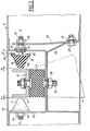
- a powertrain 1 comprising an internal combustion engine with reciprocating pistons, connected by a delivery device hydrokinetic coupling such as a torque converter, to an automatic gearbox whose output shaft 2 is substantially parallel to the axis 3 of rotation of the engine crankshaft.
- This power unit can in particular be a diesel engine fitted to a front-wheel drive vehicle, this group being mounted transversely to the direction of advance F of the vehicle.
- the wedge 7 rests on the bottom of a support 16 forming part of the structure 5, to which it is fixed by threaded rods and such nuts. as the rod 27 and the nut 28.
- the lower part of the group 1 is connected to the structure 5, in a manner known per se, by a link 8 and two elastic joints 9, 10.
- a stop 11 for the rear market On either side of the support 6, and in a horizontal direction X-X orthogonal to the axis 3, are arranged two anti-tilting stops, namely a stop 11 for the rear market, and a stop 12 for forward travel.
- the reverse stop 11 is fixed in a known manner to a support element 13 secured to a screw 14 allowing its fixing by a nut 15 on the support 16 forming part of the structure 5.
- the stop 11 is arranged at a low distance e l of a support element 17 belonging to the support 6.
- the abutment 12 of forward is attached to a support member 18 secured to a 'v is 19 which passes through the support 16 and a pretensioned elastic element, constituted in this example by a leaf spring 20, on which it is fixed between two nuts 21,22.
- the spring 20 is fixed by its end opposite to the screw 19, on a part 29 of the structure 5, by means of a bolt system 23 - nut 31.
- the spring 20 has great flexibility and is mounted prestressed, so as to press the nut 21 against an elastic washer 24 fixed on the support 16, coaxially with the screw 19.
- elastic studs 25 are fixed on the face of the support element 18 of the stopper 12 facing the support 16, so that between these studs 25 and the support 16. J, measured in the direction XX, as long as the nut 21 remains applied against the washer 24 by the spring 20. Furthermore, a clearance e 2 appears between the stop 12 and a support element 26 belonging to the support 6.
- the support element 18 of the forward travel stop 12 is mounted movable relative to its support 16, and kept spaced therefrom. the predetermined distance J in a direction perpendicular to. the axis of rotation 3 of group 1, by means of the pre-stressed spring 20 of great flexibility.
- the hydraulic coupler When the gearbox is engaged in a forward gear, the hydraulic coupler permanently ensures the coupling, by sliding of fluid, between the engine and the gearbox. Group 1 therefore transmits on the output shaft 2, as long as the vehicle is stopped, a drag torque which tends to move the vehicle forward. By reaction, the group 1 tends to tilt in the opposite direction and the support element 26 comes to bear on the stop 12.
- the prestressing force exerted by the spring 20 being slightly less than the force supported by the stop 12, under the above conditions, the nut 21 is moved away from the washer 24 without however the clearance J being caught up.
- the vibrations of group 1 are then filtered by the spring 20 of great flexibility.
- the elastic studs 25 come to bear on the support 16 because the prestressing force of the spring 20 becomes less than the force transmitted to the stop 12 by the support 6.
- the stop 12 then stops the tilting of the powertrain 1 in the usual way.
- FIG. 3 illustrates this operation, using a numerical example.
- curve A represents the force / displacement law along the X-X axis, the force being on the ordinate and the displacement (in mm) on the abscissa.
- the stiffness is very low; this stiffness is that of the spring 20, that is to say 6 daN / mm.
- the stiffness becomes very strong because it is that of the stop 12 proper.
- the anti-tilt device makes it possible to produce an anti-tilt stop which has great flexibility in the load zone corresponding to the drag torque at idle, without having the disadvantage of a high clearance for this. charge.
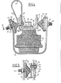
- the second embodiment, illustrated in Figures 4 and 5 comprises a support 30 secured to a power unit not shown fixed by a nut 60 on a screw 32 secured to an elastic wedge 33 itself fixed, in the usual way on a support 34 belonging to the structure of the vehicle.
- two anti-tilting stops are arranged, namely a stop 35 for reverse gear and a stop 36 for forward gear.
- the reverse stop 35 is fixed in a known manner to a support element 37 integral with a screw 38 allowing its fixing, by a nut 39, on the support 34.
- An adjustment shim 40 interposed between the element d the support 37 and the support 34 makes it possible to adjust the distance between the stop 35 and a support element 41 belonging to the support 30 to a predetermined value e 1 .
- the forward stop 36 is fixed on a support element 42 integral with a screw 4 allowing its fixing, by a nut 44, on the support 34.
- An adjustment shim 45 interposed between the support element 42 and the support 34, allows d 'adjust to a predetermined value e 2 the distance between the stop 36 of a support element 46.
- the latter consists of a branch of a leaf spring 47 folded in the shape of a hairpin.
- the second branch 48 of this leaf spring is fixed to the support 30 by means of the nut 31.
- the two chambers 46, 48 of the spring 47 are connected by a bracing member 49 which freely crosses the support 30, in a bore 50 ( Figure 4).
- the member 49 shown in detail in FIG. 4 comprises a sleeve 51 fixed to the branch 46 by a rivet 52. This sleeve freely crosses the branch 48, through an orifice 53, and has a stop shoulder 54 held in abutment against this branch 48 by the elasticity of the spring 47. In this position, a clearance J is formed between the branch 46 constituting a support element for the stop 36 and the support 30.
Landscapes
- Engineering & Computer Science (AREA)
- Chemical & Material Sciences (AREA)
- Combustion & Propulsion (AREA)
- Transportation (AREA)
- Mechanical Engineering (AREA)
- Vibration Prevention Devices (AREA)
- Motor Power Transmission Devices (AREA)
- Retarders (AREA)
Applications Claiming Priority (4)
| Application Number | Priority Date | Filing Date | Title |
|---|---|---|---|
| FR8217988 | 1982-10-27 | ||
| FR8217988A FR2535261A1 (fr) | 1982-10-27 | 1982-10-27 | Dispositif antibasculement pour groupe motopropulseur de vehicule automobile |
| FR8305455 | 1983-04-01 | ||
| FR8305455A FR2543494B2 (fr) | 1983-04-01 | 1983-04-01 | Dispositif anti-basculement pour groupe moto-propulseur de vehicule automobile |
Publications (2)
| Publication Number | Publication Date |
|---|---|
| EP0108000A1 true EP0108000A1 (de) | 1984-05-09 |
| EP0108000B1 EP0108000B1 (de) | 1986-04-02 |
Family
ID=26223125
Family Applications (1)
| Application Number | Title | Priority Date | Filing Date |
|---|---|---|---|
| EP83402016A Expired EP0108000B1 (de) | 1982-10-27 | 1983-10-17 | Anti-Kippvorrichtung für Antriebsaggregat eines Kraftfahrzeuges |
Country Status (3)
| Country | Link |
|---|---|
| US (1) | US4632211A (de) |
| EP (1) | EP0108000B1 (de) |
| DE (1) | DE3362808D1 (de) |
Cited By (7)
| Publication number | Priority date | Publication date | Assignee | Title |
|---|---|---|---|---|
| DE3721507A1 (de) * | 1987-06-30 | 1989-01-12 | Porsche Ag | Lagerung einer brennkraftmaschine |
| FR2640554A1 (fr) * | 1988-12-20 | 1990-06-22 | Renault | Dispositif antibasculement pour groupe motopropulseur de vehicule automobile suspendu elastiquement a la structure du vehicule |
| FR2736008A1 (fr) * | 1995-06-29 | 1997-01-03 | Peugeot | Module de suspension d'un groupe moto-propulseur sur la structure d'un vehicule automobile |
| EP0818340A2 (de) * | 1996-07-12 | 1998-01-14 | Dr.Ing.h.c. F. Porsche Aktiengesellschaft | Lagerung für eine Brennkraftmaschine |
| FR2794828A1 (fr) * | 1999-06-11 | 2000-12-15 | Renault | Dispositif d'amortissement par lame composite d'une piece mecanique |
| EP1669235A1 (de) * | 2004-12-13 | 2006-06-14 | Hutchinson | Einstellbarer Anschlag und Verfahren zur Kontrolle der Steifheit des Anschlags |
| EP1935695A1 (de) * | 2005-10-13 | 2008-06-25 | Toyota Jidosha Kabushiki Kaisha | Leistungsausgabevorrichtung eines hybridfahrzeugs |
Families Citing this family (3)
| Publication number | Priority date | Publication date | Assignee | Title |
|---|---|---|---|---|
| JPH0741869Y2 (ja) * | 1989-12-29 | 1995-09-27 | マツダ株式会社 | エンジンとミッションの締結構造 |
| JP3613088B2 (ja) * | 1999-09-10 | 2005-01-26 | 日産自動車株式会社 | 車両用駆動ユニット支持装置 |
| KR100423293B1 (ko) | 2001-05-11 | 2004-03-18 | 현대자동차주식회사 | 자동차의 리어서스펜션 |
Citations (14)
| Publication number | Priority date | Publication date | Assignee | Title |
|---|---|---|---|---|
| US1941763A (en) * | 1932-09-29 | 1934-01-02 | Borg Warner | Torque stabilizer spring |
| FR782906A (fr) * | 1934-03-09 | 1935-07-05 | Montage des machines alternatives sur les supports | |
| US2063063A (en) * | 1933-05-27 | 1936-12-08 | Trott | Eyed c-spring power plant mounting |
| DE741447C (de) * | 1940-10-10 | 1943-11-11 | Kloeckner Humboldt Deutz Ag | Elastische Lagerung fuer die Antriebsmaschine von Kraftfahrzeugen |
| GB617552A (en) * | 1946-10-07 | 1949-02-08 | Erf Ltd | Improvements in or relating to motor vehicle engine suspensions |
| FR979048A (fr) * | 1945-06-12 | 1951-04-20 | Metalastik Ltd | Perfectionnements aux dispositifs de suspension élastique de moteurs |
| US2648510A (en) * | 1948-07-02 | 1953-08-11 | Lord Mfg Co | Resilient mounting |
| GB777226A (en) * | 1952-10-02 | 1957-06-19 | Daimler Benz Ag | Improvements in means for suspending a driving unit on a motor vehicle |
| FR1158530A (fr) * | 1956-09-05 | 1958-06-16 | Anciens Etablissements Panhard | Infrastructure pour véhicules automobiles |
| US3730509A (en) * | 1970-04-15 | 1973-05-01 | R Jorn | Composite spring element for use as a motor mount |
| FR2322304A1 (fr) * | 1975-08-26 | 1977-03-25 | Daimler Benz Ag | Dispositif limitant l'amplitude des oscillations d'un element elastique metal-caoutchouc, en particulier pour la suspension du moteur des vehicules |
| FR2363033A1 (fr) * | 1976-08-23 | 1978-03-24 | Metzeler Kautschuk | Support elastique de moteur avec butee reglable |
| EP0038547A2 (de) * | 1980-04-21 | 1981-10-28 | Nissan Motor Co., Ltd. | Schwingungsdämpfer für Kraftfahrzeug |
| FR2487740A1 (fr) * | 1980-07-30 | 1982-02-05 | Peugeot | Dispositif anti-basculement pour groupe moto-propulseur de vehicule |
Family Cites Families (4)
| Publication number | Priority date | Publication date | Assignee | Title |
|---|---|---|---|---|
| US1912451A (en) * | 1932-04-20 | 1933-06-06 | Electrical Res Prod Inc | Vibration absorbing mounting |
| CH178298A (fr) * | 1934-08-23 | 1935-07-15 | Aubarede Paul Charles Albert M | Procédé de montage, sur un support, d'une machine comportant des pièces animées d'un mouvement alternatif. |
| US3270998A (en) * | 1964-09-30 | 1966-09-06 | Robinson Technical Products In | Elastomeric isolator |
| DE2843185C2 (de) * | 1978-10-04 | 1984-01-12 | Volkswagenwerk Ag, 3180 Wolfsburg | Schwingungsisolierende Lageranordnung für ein Antriebsaggregat |
-
1983
- 1983-10-17 DE DE8383402016T patent/DE3362808D1/de not_active Expired
- 1983-10-17 EP EP83402016A patent/EP0108000B1/de not_active Expired
- 1983-10-24 US US06/544,714 patent/US4632211A/en not_active Expired - Fee Related
Patent Citations (14)
| Publication number | Priority date | Publication date | Assignee | Title |
|---|---|---|---|---|
| US1941763A (en) * | 1932-09-29 | 1934-01-02 | Borg Warner | Torque stabilizer spring |
| US2063063A (en) * | 1933-05-27 | 1936-12-08 | Trott | Eyed c-spring power plant mounting |
| FR782906A (fr) * | 1934-03-09 | 1935-07-05 | Montage des machines alternatives sur les supports | |
| DE741447C (de) * | 1940-10-10 | 1943-11-11 | Kloeckner Humboldt Deutz Ag | Elastische Lagerung fuer die Antriebsmaschine von Kraftfahrzeugen |
| FR979048A (fr) * | 1945-06-12 | 1951-04-20 | Metalastik Ltd | Perfectionnements aux dispositifs de suspension élastique de moteurs |
| GB617552A (en) * | 1946-10-07 | 1949-02-08 | Erf Ltd | Improvements in or relating to motor vehicle engine suspensions |
| US2648510A (en) * | 1948-07-02 | 1953-08-11 | Lord Mfg Co | Resilient mounting |
| GB777226A (en) * | 1952-10-02 | 1957-06-19 | Daimler Benz Ag | Improvements in means for suspending a driving unit on a motor vehicle |
| FR1158530A (fr) * | 1956-09-05 | 1958-06-16 | Anciens Etablissements Panhard | Infrastructure pour véhicules automobiles |
| US3730509A (en) * | 1970-04-15 | 1973-05-01 | R Jorn | Composite spring element for use as a motor mount |
| FR2322304A1 (fr) * | 1975-08-26 | 1977-03-25 | Daimler Benz Ag | Dispositif limitant l'amplitude des oscillations d'un element elastique metal-caoutchouc, en particulier pour la suspension du moteur des vehicules |
| FR2363033A1 (fr) * | 1976-08-23 | 1978-03-24 | Metzeler Kautschuk | Support elastique de moteur avec butee reglable |
| EP0038547A2 (de) * | 1980-04-21 | 1981-10-28 | Nissan Motor Co., Ltd. | Schwingungsdämpfer für Kraftfahrzeug |
| FR2487740A1 (fr) * | 1980-07-30 | 1982-02-05 | Peugeot | Dispositif anti-basculement pour groupe moto-propulseur de vehicule |
Cited By (13)
| Publication number | Priority date | Publication date | Assignee | Title |
|---|---|---|---|---|
| DE3721507A1 (de) * | 1987-06-30 | 1989-01-12 | Porsche Ag | Lagerung einer brennkraftmaschine |
| US4901814A (en) * | 1987-06-30 | 1990-02-20 | Porsche Ag | Mounting of an internal combustion engine |
| FR2640554A1 (fr) * | 1988-12-20 | 1990-06-22 | Renault | Dispositif antibasculement pour groupe motopropulseur de vehicule automobile suspendu elastiquement a la structure du vehicule |
| FR2736008A1 (fr) * | 1995-06-29 | 1997-01-03 | Peugeot | Module de suspension d'un groupe moto-propulseur sur la structure d'un vehicule automobile |
| EP0818340A2 (de) * | 1996-07-12 | 1998-01-14 | Dr.Ing.h.c. F. Porsche Aktiengesellschaft | Lagerung für eine Brennkraftmaschine |
| EP0818340A3 (de) * | 1996-07-12 | 1998-03-04 | Dr.Ing.h.c. F. Porsche Aktiengesellschaft | Lagerung für eine Brennkraftmaschine |
| US5967251A (en) * | 1996-07-12 | 1999-10-19 | Dr. Ing. H.C.F. Porsche Ag | Bearing arrangement for an internal combustion engine |
| FR2794828A1 (fr) * | 1999-06-11 | 2000-12-15 | Renault | Dispositif d'amortissement par lame composite d'une piece mecanique |
| EP1669235A1 (de) * | 2004-12-13 | 2006-06-14 | Hutchinson | Einstellbarer Anschlag und Verfahren zur Kontrolle der Steifheit des Anschlags |
| FR2879274A1 (fr) * | 2004-12-13 | 2006-06-16 | Hutchinson Sa | Butee acoustique pilotable et procede de controle de la rigidite de la butee |
| EP1935695A1 (de) * | 2005-10-13 | 2008-06-25 | Toyota Jidosha Kabushiki Kaisha | Leistungsausgabevorrichtung eines hybridfahrzeugs |
| EP1935695A4 (de) * | 2005-10-13 | 2008-12-10 | Toyota Motor Co Ltd | Leistungsausgabevorrichtung eines hybridfahrzeugs |
| US7963353B2 (en) | 2005-10-13 | 2011-06-21 | Toyota Jidosha Kabushiki Kaisha | Power output device of hybrid vehicle |
Also Published As
| Publication number | Publication date |
|---|---|
| DE3362808D1 (en) | 1986-05-07 |
| US4632211A (en) | 1986-12-30 |
| EP0108000B1 (de) | 1986-04-02 |
Similar Documents
| Publication | Publication Date | Title |
|---|---|---|
| FR2561609A1 (fr) | Train de roulement pour vehicule a chenilles | |
| FR2479930A1 (fr) | Dispositif de transmission pour vehicule, comportant un accouplement a roue libre et un accouplement a friction | |
| EP0108000B1 (de) | Anti-Kippvorrichtung für Antriebsaggregat eines Kraftfahrzeuges | |
| FR2711198A1 (fr) | Biellette de reprise de couple pour moteur de véhicule . | |
| FR3019785A1 (fr) | Poutre de pare-chocs de vehicule, ensemble pare-chocs et vehicule associes | |
| WO2018091835A1 (fr) | Train de roulement pour vehicule chenille, vehicule chenille incorporant un tel train de roulement et procede de conversion d'un vehicule a roues en vehicule chenille | |
| FR2535261A1 (fr) | Dispositif antibasculement pour groupe motopropulseur de vehicule automobile | |
| FR3019603A3 (fr) | Biellette de reprise de couple pour moteur a combustion interne de vehicule et vehicule correspondant | |
| FR2702012A1 (fr) | Dispositif hydraulique de contrôle des oscillations d'un corps mobile et application au train oscillant d'un véhicule moteur. | |
| FR2559105A1 (fr) | Dispositif d'actionnement d'embrayage | |
| FR2676407A1 (fr) | Agencement d'une partie avant de vehicule automobile deformable en cas de choc frontal du vehicule. | |
| FR2894184A1 (fr) | Dispositif formant butee de detente d'une suspension d'un vehicule notamment automobile | |
| FR2789031A1 (fr) | Dispositif de protection contre un choc frontal applique a la partie avant d'un vehicule automobile | |
| FR2596010A1 (fr) | Train arriere a micro-braquage actif pour vehicule automobile | |
| FR2582996A1 (fr) | Suspension a barre de torsion | |
| FR2536019A1 (fr) | Dispositif de correction d'assiette pour vehicule automobile | |
| FR2645819A1 (fr) | Colonne de direction de securite pour vehicule automobile | |
| EP0007820B1 (de) | Verbesserung der Aufhängung eines Fahrzeugradsatzes | |
| EP0430746B1 (de) | Abstützvorrichtung, insbesondere für die Achse einer Hinterradaufhängung an der Karosserie eines Kraftfahrzeuges | |
| FR2742705A1 (fr) | Agencement d'un arbre de transmission et d'une liaison anti-couple pour groupe moto-propulseur | |
| FR2492745A1 (fr) | Dispositif de suspension d'essieu a barre de torsion | |
| WO2013110871A2 (fr) | Dispositif de fixation d'un groupe motopropulseur a la caisse d'un vehicule a moyen de liaison anti-couple | |
| EP0061944B1 (de) | Radsatz für Fahrzeug | |
| EP1193099B1 (de) | Aufhängungstange einer Antriebseinheit eines Kraftfahrzeuges und Aufhängevorrichtung mit einer solchen Stange | |
| FR2475991A1 (fr) | Dispositif de roues jumelees pour tracteurs et engins analogues |
Legal Events
| Date | Code | Title | Description |
|---|---|---|---|
| PUAI | Public reference made under article 153(3) epc to a published international application that has entered the european phase |
Free format text: ORIGINAL CODE: 0009012 |
|
| 17P | Request for examination filed |
Effective date: 19840220 |
|
| AK | Designated contracting states |
Designated state(s): DE GB IT |
|
| ITF | It: translation for a ep patent filed |
Owner name: BARZANO' E ZANARDO MILANO S.P.A. |
|
| GRAA | (expected) grant |
Free format text: ORIGINAL CODE: 0009210 |
|
| AK | Designated contracting states |
Kind code of ref document: B1 Designated state(s): DE GB IT |
|
| REF | Corresponds to: |
Ref document number: 3362808 Country of ref document: DE Date of ref document: 19860507 |
|
| PLBE | No opposition filed within time limit |
Free format text: ORIGINAL CODE: 0009261 |
|
| STAA | Information on the status of an ep patent application or granted ep patent |
Free format text: STATUS: NO OPPOSITION FILED WITHIN TIME LIMIT |
|
| 26N | No opposition filed | ||
| REG | Reference to a national code |
Ref country code: GB Ref legal event code: 746 |
|
| ITPR | It: changes in ownership of a european patent |
Owner name: OFFERTA DI LICENZA AL PUBBLICO |
|
| PGFP | Annual fee paid to national office [announced via postgrant information from national office to epo] |
Ref country code: DE Payment date: 19920819 Year of fee payment: 10 |
|
| PGFP | Annual fee paid to national office [announced via postgrant information from national office to epo] |
Ref country code: GB Payment date: 19921009 Year of fee payment: 10 |
|
| ITTA | It: last paid annual fee | ||
| PG25 | Lapsed in a contracting state [announced via postgrant information from national office to epo] |
Ref country code: GB Effective date: 19931017 |
|
| GBPC | Gb: european patent ceased through non-payment of renewal fee |
Effective date: 19931017 |
|
| PG25 | Lapsed in a contracting state [announced via postgrant information from national office to epo] |
Ref country code: DE Effective date: 19940701 |