EP0106940B1 - An arrangement for the measurement of the difference between two flows in two separate ducts - Google Patents
An arrangement for the measurement of the difference between two flows in two separate ducts Download PDFInfo
- Publication number
- EP0106940B1 EP0106940B1 EP83106547A EP83106547A EP0106940B1 EP 0106940 B1 EP0106940 B1 EP 0106940B1 EP 83106547 A EP83106547 A EP 83106547A EP 83106547 A EP83106547 A EP 83106547A EP 0106940 B1 EP0106940 B1 EP 0106940B1
- Authority
- EP
- European Patent Office
- Prior art keywords
- ducts
- duct
- measurement
- arrangement
- difference
- Prior art date
- Legal status (The legal status is an assumption and is not a legal conclusion. Google has not performed a legal analysis and makes no representation as to the accuracy of the status listed.)
- Expired
Links
Images
Classifications
-
- G—PHYSICS
- G01—MEASURING; TESTING
- G01F—MEASURING VOLUME, VOLUME FLOW, MASS FLOW OR LIQUID LEVEL; METERING BY VOLUME
- G01F1/00—Measuring the volume flow or mass flow of fluid or fluent solid material wherein the fluid passes through a meter in a continuous flow
- G01F1/56—Measuring the volume flow or mass flow of fluid or fluent solid material wherein the fluid passes through a meter in a continuous flow by using electric or magnetic effects
-
- A—HUMAN NECESSITIES
- A61—MEDICAL OR VETERINARY SCIENCE; HYGIENE
- A61M—DEVICES FOR INTRODUCING MEDIA INTO, OR ONTO, THE BODY; DEVICES FOR TRANSDUCING BODY MEDIA OR FOR TAKING MEDIA FROM THE BODY; DEVICES FOR PRODUCING OR ENDING SLEEP OR STUPOR
- A61M1/00—Suction or pumping devices for medical purposes; Devices for carrying-off, for treatment of, or for carrying-over, body-liquids; Drainage systems
- A61M1/14—Dialysis systems; Artificial kidneys; Blood oxygenators ; Reciprocating systems for treatment of body fluids, e.g. single needle systems for hemofiltration or pheresis
- A61M1/16—Dialysis systems; Artificial kidneys; Blood oxygenators ; Reciprocating systems for treatment of body fluids, e.g. single needle systems for hemofiltration or pheresis with membranes
-
- F—MECHANICAL ENGINEERING; LIGHTING; HEATING; WEAPONS; BLASTING
- F02—COMBUSTION ENGINES; HOT-GAS OR COMBUSTION-PRODUCT ENGINE PLANTS
- F02P—IGNITION, OTHER THAN COMPRESSION IGNITION, FOR INTERNAL-COMBUSTION ENGINES; TESTING OF IGNITION TIMING IN COMPRESSION-IGNITION ENGINES
- F02P5/00—Advancing or retarding ignition; Control therefor
- F02P5/04—Advancing or retarding ignition; Control therefor automatically, as a function of the working conditions of the engine or vehicle or of the atmospheric conditions
- F02P5/145—Advancing or retarding ignition; Control therefor automatically, as a function of the working conditions of the engine or vehicle or of the atmospheric conditions using electrical means
- F02P5/15—Digital data processing
- F02P5/152—Digital data processing dependent on pinking
-
- G—PHYSICS
- G01—MEASURING; TESTING
- G01F—MEASURING VOLUME, VOLUME FLOW, MASS FLOW OR LIQUID LEVEL; METERING BY VOLUME
- G01F1/00—Measuring the volume flow or mass flow of fluid or fluent solid material wherein the fluid passes through a meter in a continuous flow
- G01F1/56—Measuring the volume flow or mass flow of fluid or fluent solid material wherein the fluid passes through a meter in a continuous flow by using electric or magnetic effects
- G01F1/58—Measuring the volume flow or mass flow of fluid or fluent solid material wherein the fluid passes through a meter in a continuous flow by using electric or magnetic effects by electromagnetic flowmeters
-
- G—PHYSICS
- G01—MEASURING; TESTING
- G01F—MEASURING VOLUME, VOLUME FLOW, MASS FLOW OR LIQUID LEVEL; METERING BY VOLUME
- G01F15/00—Details of, or accessories for, apparatus of groups G01F1/00 - G01F13/00 insofar as such details or appliances are not adapted to particular types of such apparatus
-
- G—PHYSICS
- G01—MEASURING; TESTING
- G01F—MEASURING VOLUME, VOLUME FLOW, MASS FLOW OR LIQUID LEVEL; METERING BY VOLUME
- G01F15/00—Details of, or accessories for, apparatus of groups G01F1/00 - G01F13/00 insofar as such details or appliances are not adapted to particular types of such apparatus
- G01F15/18—Supports or connecting means for meters
-
- G—PHYSICS
- G01—MEASURING; TESTING
- G01L—MEASURING FORCE, STRESS, TORQUE, WORK, MECHANICAL POWER, MECHANICAL EFFICIENCY, OR FLUID PRESSURE
- G01L23/00—Devices or apparatus for measuring or indicating or recording rapid changes, such as oscillations, in the pressure of steam, gas, or liquid; Indicators for determining work or energy of steam, internal-combustion, or other fluid-pressure engines from the condition of the working fluid
- G01L23/22—Devices or apparatus for measuring or indicating or recording rapid changes, such as oscillations, in the pressure of steam, gas, or liquid; Indicators for determining work or energy of steam, internal-combustion, or other fluid-pressure engines from the condition of the working fluid for detecting or indicating knocks in internal-combustion engines; Units comprising pressure-sensitive members combined with ignitors for firing internal-combustion engines
- G01L23/221—Devices or apparatus for measuring or indicating or recording rapid changes, such as oscillations, in the pressure of steam, gas, or liquid; Indicators for determining work or energy of steam, internal-combustion, or other fluid-pressure engines from the condition of the working fluid for detecting or indicating knocks in internal-combustion engines; Units comprising pressure-sensitive members combined with ignitors for firing internal-combustion engines for detecting or indicating knocks in internal combustion engines
- G01L23/225—Devices or apparatus for measuring or indicating or recording rapid changes, such as oscillations, in the pressure of steam, gas, or liquid; Indicators for determining work or energy of steam, internal-combustion, or other fluid-pressure engines from the condition of the working fluid for detecting or indicating knocks in internal-combustion engines; Units comprising pressure-sensitive members combined with ignitors for firing internal-combustion engines for detecting or indicating knocks in internal combustion engines circuit arrangements therefor
-
- Y—GENERAL TAGGING OF NEW TECHNOLOGICAL DEVELOPMENTS; GENERAL TAGGING OF CROSS-SECTIONAL TECHNOLOGIES SPANNING OVER SEVERAL SECTIONS OF THE IPC; TECHNICAL SUBJECTS COVERED BY FORMER USPC CROSS-REFERENCE ART COLLECTIONS [XRACs] AND DIGESTS
- Y02—TECHNOLOGIES OR APPLICATIONS FOR MITIGATION OR ADAPTATION AGAINST CLIMATE CHANGE
- Y02T—CLIMATE CHANGE MITIGATION TECHNOLOGIES RELATED TO TRANSPORTATION
- Y02T10/00—Road transport of goods or passengers
- Y02T10/10—Internal combustion engine [ICE] based vehicles
- Y02T10/40—Engine management systems
Definitions
- the present invention relates to an arrangement forthe measurement of the difference between the rates of two mass flows in two separate ducts with one or more monitoring electrodes, arranged in each duct.
- the invention relates first and foremost to the measurement of relatively small differences between two relatively large mass flows.
- the invention may be applied, for example, to the measurement of ultrafiltration in a dialysis system, where the continuing clean dialysis solution flows through the one duct, whilst the same solution, but increased through ultrafiltration in the dialyzer, flows through the other duct.
- the two main mass flows may be of the order of magnitude 500 ml/min whereas the difference, that is to say the ultrafiltration, may be somewhere between 0 and 40 ml/min and exceptionally a little higher.
- Both systems suffer from the disadvantage that the flowing media act upon the two ducts, or the electrodes, in a different manner. If, for example, the designs are used for the measurement of ultrafiltration in dialysis, deposits from the contaminated liquid are obtained on the electrodes and/or on the actual duct walls. Even a deposit in the order of magnitudes of a few um may cause substantial errors in the readings.
- the invention thus relates to an arrangement for the measurement of the difference between the rates of two mass flows in two separate ducts with one or more monitoring electrodes arranged in each duct.
- valve means are provided for the alternate change-over of the mass flows from one duct to the other duct and vice-versa, so that ultimately all electrodes and/or duct walls are acted upon to a substantially equal extent.
- This realization has the advantage that the dialysis or any other continuing treatment can proceed without interruption.
- valve means are provided for the conducting of one and the same mass flow through both ducts, providing a zero difference value to be used as a new zero value for the continued measurement.
- the lastmentioned system is used for the measurement and possible control of the mass flow to and from a dialyzer, the same is appropriately provided with means for the conducting of the clean dialysis solution through both the ducts.
- the invention is used preferably for an arrangement wherein the said electrodes are arranged in a manner known in itself in a magnetic field crossing the two ducts. Signals emitted from the electrodes can then be picked up and used directly for the adjustment in case of large differences in the mass flows, whilstthe difference in signals can be picked up and used for adjustment in case of small differences in the mass flows.
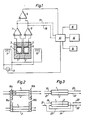
- Fig. 1 two ducts 1 and 2 with four electrodes 3, 4, 5 and 6 which are connected to differential measuring instruments 7 and 8 respectively which in turn are connected to a differential measuring instrument 9. All differential measuring instruments are connected to a microcomputer 10; The mass flows in the two ducts 1 and 2 are subjected to a magnetic field generated with the help of the coils 11 and 12, operated by a source of current 13, which in turn is controlled by the computer 10. It is shown schematically how the computer can be provided with a display 14 and a controller 15. At the same time the microcomputer can be adapted so as to control one or more valves 16. With regards to the theories behind the measurement in accordance with the system shown, reference is made to the aforementioned British publications.
- the broken lines 17 and 18 are intended to indicate that the measured values obtained from the differential measuring instruments 7 and 8 are used directly for the control of the computer 10. This is done in the case of large differences between the flows in the ducts 1 and 2. In the case of small differences the difference obtained from the differential measuring instrument 9 is used instead for the control of the microcomputer 10.
- the system may be provided for this purpose with different types of amplifiers, rectifiers, earth electrodes and other electric components which are normal for anyone versed in the art.
- ducts 1 and 2 are shown in a cross- section transversely to the direction of flow.
- corresponding ducts are shown instead in their longitudinal direction.
- Ducts 1 and 2 are combined with two valve blocks 16a and 16b by means of which the mass flows through ducts 1 and 2, respectively, can be changed over alternately to the opposite duct, so that ultimately all electrodes and/or duct walls are acted upon to a substantially equal extent.
- ducts 1 and 2 are also shown in longitudinal direction.
- the arrow 19 may designate the mass flow from a control unit normally used for dialysis.
- the arrow 20 in this case designates the mass flow to the actual dialyzer and the arrow 21 the mass flow from the dialyzer.
- the arrow 22 in this case designates the mass flow to a drain and/or to a possible regeneration and recirculation.
- the arrow 23 indicates how the clean dialysis solution can be conducted first through the duct 1 and then through the duct 2 to be removed finally to a drain or the like without passing the dialyzer.
- the arrow 24 is meant to indicate how the mass flow from the dialyzer can be conducted, past the two ducts 1 and 2, directly to the drain.
- the system in accordance with Fig. 3 has the advantage over the system in accordance with Fig. 2 that there is no risk of any particles broken loose from a previously contaminated duct being passed to the dialyzer. In accordance with this system any contaminations broken off are passed instead directly to the drain.
- the invention is not limited simply to the preferred embodiment described above, but can be varied within the scope of the following claims.
- the invention is also applicable, for example, to systems with more or fewer electrodes.
- the system can also be adapted to counter-current flow.
- the calibration in accordance with the system shown in Fig. 3 can be repeated more or less frequently at regular intervals.
- the calibration may proceed in such a manner that the mass flow difference is measured 300-400 times in a minute, whereupon a mean value is calculated which is substantially independent of any background noise.
Landscapes
- Engineering & Computer Science (AREA)
- Health & Medical Sciences (AREA)
- Physics & Mathematics (AREA)
- Chemical & Material Sciences (AREA)
- Combustion & Propulsion (AREA)
- General Physics & Mathematics (AREA)
- Fluid Mechanics (AREA)
- Heart & Thoracic Surgery (AREA)
- Urology & Nephrology (AREA)
- Hematology (AREA)
- Signal Processing (AREA)
- Vascular Medicine (AREA)
- Anesthesiology (AREA)
- Biomedical Technology (AREA)
- Electromagnetism (AREA)
- Life Sciences & Earth Sciences (AREA)
- Animal Behavior & Ethology (AREA)
- General Health & Medical Sciences (AREA)
- Public Health (AREA)
- Veterinary Medicine (AREA)
- Emergency Medicine (AREA)
- Mechanical Engineering (AREA)
- General Engineering & Computer Science (AREA)
- External Artificial Organs (AREA)
- Automatic Analysis And Handling Materials Therefor (AREA)
- Measuring Volume Flow (AREA)
- Separation Using Semi-Permeable Membranes (AREA)
- Paper (AREA)
- Joints Allowing Movement (AREA)
- Farming Of Fish And Shellfish (AREA)
Priority Applications (1)
| Application Number | Priority Date | Filing Date | Title |
|---|---|---|---|
| AT83106547T ATE25552T1 (de) | 1982-09-28 | 1983-07-05 | Anordnung zum messen der differenz zwischen zwei stroemungen in zwei verschiedenen leitungen. |
Applications Claiming Priority (2)
| Application Number | Priority Date | Filing Date | Title |
|---|---|---|---|
| SE8205529 | 1982-09-28 | ||
| SE8205529A SE434192B (sv) | 1982-09-28 | 1982-09-28 | Anordning for metning av skillnaden mellan tva floden i tva skilda kanaler |
Publications (3)
| Publication Number | Publication Date |
|---|---|
| EP0106940A2 EP0106940A2 (en) | 1984-05-02 |
| EP0106940A3 EP0106940A3 (en) | 1984-07-18 |
| EP0106940B1 true EP0106940B1 (en) | 1987-02-25 |
Family
ID=20348004
Family Applications (1)
| Application Number | Title | Priority Date | Filing Date |
|---|---|---|---|
| EP83106547A Expired EP0106940B1 (en) | 1982-09-28 | 1983-07-05 | An arrangement for the measurement of the difference between two flows in two separate ducts |
Country Status (6)
| Country | Link |
|---|---|
| US (1) | US4585552A (it) |
| EP (1) | EP0106940B1 (it) |
| JP (1) | JPH0752114B2 (it) |
| AT (1) | ATE25552T1 (it) |
| DE (1) | DE3369882D1 (it) |
| SE (2) | SE434192B (it) |
Families Citing this family (17)
| Publication number | Priority date | Publication date | Assignee | Title |
|---|---|---|---|---|
| SE447963B (sv) * | 1985-06-04 | 1987-01-12 | Gambro Ab | System for styrning av dialys |
| US4827430A (en) * | 1987-05-11 | 1989-05-02 | Baxter International Inc. | Flow measurement system |
| SE500491C2 (sv) * | 1991-02-04 | 1994-07-04 | Gambro Ab | Mätanordning innefattande minst en mätelektrod samt sätt att rengöra en mätelektrod |
| JPH05329205A (ja) * | 1991-10-01 | 1993-12-14 | Fumio Watanabe | 人工透析装置 |
| SE513524C2 (sv) * | 1994-02-18 | 2000-09-25 | Gambro Med Tech Ab | System jämte förfarande för beräkning och/eller övervakning av ett vätskeflöde i en dialysapparat |
| SE510286C2 (sv) * | 1997-09-22 | 1999-05-10 | Gambro Med Tech Ab | Förfarande och anordning för övervakning av infusionspump i en hemo- eller hemodiafiltreringsmaskin |
| US6331252B1 (en) | 1998-07-31 | 2001-12-18 | Baxter International Inc. | Methods for priming a blood compartment of a hemodialyzer |
| GB9821159D0 (en) * | 1998-09-29 | 1998-11-25 | Scient Generics Ltd | Metering device |
| US20090235602A1 (en) * | 2008-03-21 | 2009-09-24 | Ceccofiglio David H | Strengthened shutter system |
| DE202008012801U1 (de) * | 2008-09-26 | 2010-03-04 | Gebr. Kemper Gmbh + Co. Kg | Messarmatur |
| DE102010003642A1 (de) * | 2010-03-15 | 2011-09-15 | Fresenius Medical Care Deutschland Gmbh | Kassette mit einem Sensor zur Bestimmung der Differenz eines ersten und eines zweiten Flüssigkeitsstroms |
| DE102011114506A1 (de) * | 2011-09-22 | 2013-03-28 | Technische Universität Ilmenau | Verfahren und Vorrichtung zur berührungslosen Messung eines Massen- oder Volumenstromes eines elektrisch leitfähigen Fluids |
| EP3021887B1 (en) | 2013-07-15 | 2019-03-27 | Gambro Lundia AB | Individual pump calibration for ultrafiltration control in a dialysis apparatus |
| CN104470554B (zh) | 2013-07-15 | 2017-03-08 | 甘布罗伦迪亚股份公司 | 用于透析装置中的超滤控制的相对泵校准 |
| DE102014009444A1 (de) | 2014-06-25 | 2015-12-31 | Fresenius Medical Care Deutschland Gmbh | Flussmesser und Kassettenmodul für einen Flussmesser |
| JP6395568B2 (ja) * | 2014-11-13 | 2018-09-26 | 愛知時計電機株式会社 | 流量計測器及び電磁流量計 |
| DE102015001406B3 (de) * | 2015-02-04 | 2016-07-14 | Fresenius Medical Care Deutschland Gmbh | Kassettenmodul für einen Differenzflussmesser und Differenzflussmesser |
Family Cites Families (14)
| Publication number | Priority date | Publication date | Assignee | Title |
|---|---|---|---|---|
| DE614566C (de) * | 1933-10-31 | 1935-06-17 | Askania Werke Akt Ges Vormals | Verfahren und Vorrichtung zur Regelung von Gemischen |
| DE623889C (de) * | 1934-11-11 | 1936-01-08 | Siemens & Halske Akt Ges | Gemischregler |
| US3002379A (en) * | 1958-12-19 | 1961-10-03 | Phillips Petroleum Co | Process and apparatus for magnetic flow measurement |
| GB1126954A (en) * | 1966-02-25 | 1968-09-11 | Distillers Co Yeast Ltd | Flow rate measuring device |
| DE1573007A1 (de) * | 1966-06-18 | 1970-06-18 | Krohne Fa Ludwig | Messanordnung mit Mengenmessung des Zulaufs und des Ruecklaufs |
| BE757310A (fr) * | 1969-10-11 | 1971-04-09 | Siemens Ag | Procede pour la determination de la difference volumetrique de deux courants de matiere par la mesure inductive du debit |
| DE2214735A1 (de) * | 1972-03-25 | 1973-09-27 | Appelt Otto Heinrich Dipl Ing | Elektronischer durchflussmesser fuer fluessigkeiten |
| US3990973A (en) * | 1974-11-04 | 1976-11-09 | Cobe Laboratories, Inc. | Apparatus for measuring ultrafiltration rate |
| JPS525585A (en) * | 1975-07-03 | 1977-01-17 | Toshiba Corp | Pressure difference |
| GB2003274B (en) * | 1977-07-12 | 1982-02-24 | Repgreen Ltd | Measurement method and apparatus |
| GB2056691B (en) * | 1979-08-17 | 1984-05-16 | Sanderson M | Differential electromagneic flowmeters |
| DE3020756A1 (de) * | 1980-05-31 | 1981-12-10 | Salvia Regel- Und Medizintechnik Gmbh, 6231 Schwalbach | Messung des fluessigkeitsentzuges an einem dialysesystem |
| CA1188998A (en) * | 1980-11-12 | 1985-06-18 | Stephen R. Ash | System and method for controlling and monitoring blood or biologic fluid flow |
| US4486303A (en) * | 1981-10-06 | 1984-12-04 | Brous Donald W | Ultrafiltration in hemodialysis |
-
1982
- 1982-09-28 SE SE8205529A patent/SE434192B/sv not_active IP Right Cessation
-
1983
- 1983-07-05 AT AT83106547T patent/ATE25552T1/de not_active IP Right Cessation
- 1983-07-05 DE DE8383106547T patent/DE3369882D1/de not_active Expired
- 1983-07-05 EP EP83106547A patent/EP0106940B1/en not_active Expired
- 1983-09-12 US US06/531,277 patent/US4585552A/en not_active Expired - Lifetime
- 1983-09-15 SE SE8304964A patent/SE434886B/sv not_active IP Right Cessation
- 1983-09-26 JP JP58176536A patent/JPH0752114B2/ja not_active Expired - Lifetime
Also Published As
| Publication number | Publication date |
|---|---|
| JPH0752114B2 (ja) | 1995-06-05 |
| SE8304964L (it) | 1984-08-20 |
| SE434886B (sv) | 1984-08-20 |
| JPS5979810A (ja) | 1984-05-09 |
| SE8304964D0 (sv) | 1983-09-15 |
| SE8205529L (sv) | 1984-03-29 |
| SE8205529D0 (sv) | 1982-09-28 |
| ATE25552T1 (de) | 1987-03-15 |
| DE3369882D1 (en) | 1987-04-02 |
| US4585552A (en) | 1986-04-29 |
| SE434192B (sv) | 1984-07-09 |
| EP0106940A3 (en) | 1984-07-18 |
| EP0106940A2 (en) | 1984-05-02 |
Similar Documents
| Publication | Publication Date | Title |
|---|---|---|
| EP0106940A2 (en) | An arrangement for the measurement of the difference between two flows in two separate ducts | |
| Ohlsen et al. | Techniques for measurement of spin-12 and spin-1 polarization analyzing tensors | |
| EP0159157B1 (en) | Filter cleaning system for opacity monitor | |
| FR2709012A1 (fr) | Disque d'enregistrement magnétique, système de suivi de piste pour ce disque et procédé correspondant. | |
| EP3564685B1 (en) | System and method for sensor diagnostics during functional operation | |
| EP0514027B1 (en) | Magnetic noise reducing device for a squid magnetometer | |
| DE102015001406B3 (de) | Kassettenmodul für einen Differenzflussmesser und Differenzflussmesser | |
| EP0096416A2 (en) | Optical fiber gyro | |
| EP3161426A1 (de) | Flussmesser und kassettenmodul für einen flussmesser | |
| US5786895A (en) | Means and method for active dispersion equalization of a multioscillator ring laser gyroscope | |
| EP0675339A1 (en) | Geomagnetic direction sensor | |
| EP1189037A1 (de) | Coriolisdurchflussmesser mit digitalem Steuerungssystem | |
| JPS5775318A (en) | Measuring device for traveling locus shift of selftraveling car | |
| ES2117578A1 (es) | Sistema para medir el potencial zeta de suspensiones de particulas. | |
| DE102004056370A1 (de) | Mess- und Betriebsschaltung für Coriolismassedurchflussaufnehmer | |
| JPH04319623A (ja) | 測定装置及びこの装置の測定電極の清浄化法 | |
| JPH028209Y2 (it) | ||
| SU1691821A1 (ru) | Система управлени транспортным средством | |
| SU1357920A1 (ru) | Устройство дл определени местоположени транспортного средства | |
| SU1534322A1 (ru) | Электромагнитный расходомер | |
| SU1412472A1 (ru) | Комплексный измеритель азимута и дальности | |
| JPS6327203Y2 (it) | ||
| JP2026065241A (ja) | 磁気検出システム及び磁気検出方法 | |
| SU917146A1 (ru) | Устройство дл определени амплитудных распределений скачков Баркгаузена | |
| SU1553932A1 (ru) | Устройство дл контрол ферромагнитных колец |
Legal Events
| Date | Code | Title | Description |
|---|---|---|---|
| PUAI | Public reference made under article 153(3) epc to a published international application that has entered the european phase |
Free format text: ORIGINAL CODE: 0009012 |
|
| AK | Designated contracting states |
Designated state(s): AT BE CH DE FR GB IT LI LU NL |
|
| PUAL | Search report despatched |
Free format text: ORIGINAL CODE: 0009013 |
|
| AK | Designated contracting states |
Designated state(s): AT BE CH DE FR GB IT LI LU NL |
|
| 17P | Request for examination filed |
Effective date: 19840820 |
|
| ITF | It: translation for a ep patent filed | ||
| GRAA | (expected) grant |
Free format text: ORIGINAL CODE: 0009210 |
|
| AK | Designated contracting states |
Kind code of ref document: B1 Designated state(s): AT BE CH DE FR GB IT LI LU NL |
|
| PG25 | Lapsed in a contracting state [announced via postgrant information from national office to epo] |
Ref country code: AT Effective date: 19870225 |
|
| REF | Corresponds to: |
Ref document number: 25552 Country of ref document: AT Date of ref document: 19870315 Kind code of ref document: T |
|
| REF | Corresponds to: |
Ref document number: 3369882 Country of ref document: DE Date of ref document: 19870402 |
|
| ET | Fr: translation filed | ||
| PG25 | Lapsed in a contracting state [announced via postgrant information from national office to epo] |
Ref country code: LU Free format text: LAPSE BECAUSE OF NON-PAYMENT OF DUE FEES Effective date: 19870731 |
|
| PLBE | No opposition filed within time limit |
Free format text: ORIGINAL CODE: 0009261 |
|
| STAA | Information on the status of an ep patent application or granted ep patent |
Free format text: STATUS: NO OPPOSITION FILED WITHIN TIME LIMIT |
|
| 26N | No opposition filed | ||
| ITTA | It: last paid annual fee | ||
| REG | Reference to a national code |
Ref country code: GB Ref legal event code: IF02 |
|
| PGFP | Annual fee paid to national office [announced via postgrant information from national office to epo] |
Ref country code: FR Payment date: 20020516 Year of fee payment: 20 |
|
| PGFP | Annual fee paid to national office [announced via postgrant information from national office to epo] |
Ref country code: GB Payment date: 20020621 Year of fee payment: 20 |
|
| PGFP | Annual fee paid to national office [announced via postgrant information from national office to epo] |
Ref country code: CH Payment date: 20020701 Year of fee payment: 20 |
|
| PGFP | Annual fee paid to national office [announced via postgrant information from national office to epo] |
Ref country code: NL Payment date: 20020731 Year of fee payment: 20 |
|
| PGFP | Annual fee paid to national office [announced via postgrant information from national office to epo] |
Ref country code: BE Payment date: 20020806 Year of fee payment: 20 |
|
| PGFP | Annual fee paid to national office [announced via postgrant information from national office to epo] |
Ref country code: DE Payment date: 20020925 Year of fee payment: 20 |
|
| PG25 | Lapsed in a contracting state [announced via postgrant information from national office to epo] |
Ref country code: LI Free format text: LAPSE BECAUSE OF EXPIRATION OF PROTECTION Effective date: 20030704 Ref country code: GB Free format text: LAPSE BECAUSE OF EXPIRATION OF PROTECTION Effective date: 20030704 Ref country code: CH Free format text: LAPSE BECAUSE OF EXPIRATION OF PROTECTION Effective date: 20030704 |
|
| PG25 | Lapsed in a contracting state [announced via postgrant information from national office to epo] |
Ref country code: NL Free format text: LAPSE BECAUSE OF EXPIRATION OF PROTECTION Effective date: 20030705 |
|
| REG | Reference to a national code |
Ref country code: GB Ref legal event code: PE20 |
|
| REG | Reference to a national code |
Ref country code: CH Ref legal event code: PL |
|
| NLV7 | Nl: ceased due to reaching the maximum lifetime of a patent |
Effective date: 20030705 |