EP0106820A2 - Vorrichtung zur Steuerung der Abgasrückführung bei aufgeladener Brennkraftmaschine - Google Patents
Vorrichtung zur Steuerung der Abgasrückführung bei aufgeladener Brennkraftmaschine Download PDFInfo
- Publication number
- EP0106820A2 EP0106820A2 EP83850263A EP83850263A EP0106820A2 EP 0106820 A2 EP0106820 A2 EP 0106820A2 EP 83850263 A EP83850263 A EP 83850263A EP 83850263 A EP83850263 A EP 83850263A EP 0106820 A2 EP0106820 A2 EP 0106820A2
- Authority
- EP
- European Patent Office
- Prior art keywords
- conduit
- intake
- valve
- throttle valve
- outer chamber
- Prior art date
- Legal status (The legal status is an assumption and is not a legal conclusion. Google has not performed a legal analysis and makes no representation as to the accuracy of the status listed.)
- Granted
Links
Images
Classifications
-
- F—MECHANICAL ENGINEERING; LIGHTING; HEATING; WEAPONS; BLASTING
- F02—COMBUSTION ENGINES; HOT-GAS OR COMBUSTION-PRODUCT ENGINE PLANTS
- F02D—CONTROLLING COMBUSTION ENGINES
- F02D21/00—Controlling engines characterised by their being supplied with non-airborne oxygen or other non-fuel gas
- F02D21/06—Controlling engines characterised by their being supplied with non-airborne oxygen or other non-fuel gas peculiar to engines having other non-fuel gas added to combustion air
- F02D21/08—Controlling engines characterised by their being supplied with non-airborne oxygen or other non-fuel gas peculiar to engines having other non-fuel gas added to combustion air the other gas being the exhaust gas of engine
-
- F—MECHANICAL ENGINEERING; LIGHTING; HEATING; WEAPONS; BLASTING
- F02—COMBUSTION ENGINES; HOT-GAS OR COMBUSTION-PRODUCT ENGINE PLANTS
- F02M—SUPPLYING COMBUSTION ENGINES IN GENERAL WITH COMBUSTIBLE MIXTURES OR CONSTITUENTS THEREOF
- F02M26/00—Engine-pertinent apparatus for adding exhaust gases to combustion-air, main fuel or fuel-air mixture, e.g. by exhaust gas recirculation [EGR] systems
- F02M26/02—EGR systems specially adapted for supercharged engines
- F02M26/04—EGR systems specially adapted for supercharged engines with a single turbocharger
- F02M26/05—High pressure loops, i.e. wherein recirculated exhaust gas is taken out from the exhaust system upstream of the turbine and reintroduced into the intake system downstream of the compressor
-
- F—MECHANICAL ENGINEERING; LIGHTING; HEATING; WEAPONS; BLASTING
- F02—COMBUSTION ENGINES; HOT-GAS OR COMBUSTION-PRODUCT ENGINE PLANTS
- F02M—SUPPLYING COMBUSTION ENGINES IN GENERAL WITH COMBUSTIBLE MIXTURES OR CONSTITUENTS THEREOF
- F02M26/00—Engine-pertinent apparatus for adding exhaust gases to combustion-air, main fuel or fuel-air mixture, e.g. by exhaust gas recirculation [EGR] systems
- F02M26/52—Systems for actuating EGR valves
- F02M26/55—Systems for actuating EGR valves using vacuum actuators
-
- F—MECHANICAL ENGINEERING; LIGHTING; HEATING; WEAPONS; BLASTING
- F02—COMBUSTION ENGINES; HOT-GAS OR COMBUSTION-PRODUCT ENGINE PLANTS
- F02B—INTERNAL-COMBUSTION PISTON ENGINES; COMBUSTION ENGINES IN GENERAL
- F02B1/00—Engines characterised by fuel-air mixture compression
- F02B1/02—Engines characterised by fuel-air mixture compression with positive ignition
- F02B1/04—Engines characterised by fuel-air mixture compression with positive ignition with fuel-air mixture admission into cylinder
Definitions
- the present invention relates to an arrangement for controlling exhaust gas recirculation (EGR) in a supercharged internal combustion engine equipped with an intake system and an exhaust system and between said systems a conduit arranged for recirculating exhaust gases to an intake conduit in the engine intake system, the exhaust recirculation being controlled by a valve under the influence of the engine intake pressure and at least one spring arranged in the control means.
- EGR exhaust gas recirculation
- a spring arranged in the outer chamber is then able to push the membrane separating the chambers and a valve means connected thereto to a closed valve position in which the recirculation of exhaust gases ceases.
- the subatmospheric pressure in the intake system overcomes the spring force and opens the valve to.recirculate exhaust gases to the intake system.
- An EGR valve of double membrane type is arranged to control the EGR amount in response to the pressure in two pressure outlets disposed in the intake system as described above.
- the present invention relates to an arrangement which in a simple manner makes it possible to control the exhaust gas-recirculation (EGR) in a supercharged internal combustion engine of the type described in the introduction to the description.
- the exhaust gas recirculation is controlled by a valve comprising a slidably mounted valve spindle which cooperates with a membrane in a control means.
- the membrane separates an outer chamber and an inner chamber and is arranged to become axially displaced by the engine intake pressure and at least one spring or the like arranged in the control means, the outer chamber in the control means being connected by a conduit to the intake conduit immediately upstream of the idle position for a throttle valve pivotably mounted in the intake conduit.
- the invention is characterized in that the inner chamber is connected via a conduit to the intake conduit upstream of the conduit connection from the outer chamber but downstream of a compressor included in the intake system whereby, when there is a certain overpressure in the inner chamber relative to the outer chamber, the force exerted on the membrane by the spring can be overcome and thereby cause the valve spindle to open the conduit.
- the inventive arrangement makes it possible to modify an EGR valve known from suction engines to include a second sealed chamber which is connected to the intake system in the above-stated manner.
- the valve will thus control the EGR amount only in response to the pressure differential between the connections in the intake conduit. If both - chambers are supplied with overpressure, this will make no difference for the functioning of the EGR valve.
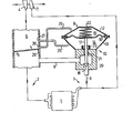
- the figure shows schematically an Otto engine 1 which is designed to be supplied with a fuel-air mixture via an intake system 2 and from which engine exhaust gases are led off via an exhaust system 3.
- the intake system 2 comprises a centrifugal compressor 4 which under operating conditions can produce an overpressure in an intake conduit 6 located downstream thereof.
- a throttle valve 5 operable by the driver, whereby the driver can regualte the fuel-air mixture supplied to the engine 1.
- the fuel can be supplied to the intake system 2 either via carburettors or via injection nozzles (not shown).
- the exhaust system 3 comprises an exhaust turbine 7 driven by the exhaust.gases. This turbine drives in turn the compressor 4 via a shaft common to both the turbine 7 and the compressor 4. A certain amount of exhaust gases. can be recirculated to the intake conduit 6 via a conduit 9 which is arranged to cooperate with a control valve 10, hereinafter called the EGR valve.
- a control valve 10 hereinafter called the EGR valve.
- Said EGR valve 10 comprises a control means 8 and a valve housing 20 securely joined to each other.
- the control means 8 consists of two housing halves 12,13 between which a membrane 16 is held along the periphery thereof, thus separating an inner chamber 14 and an outer chamber 15.
- a valve member in the form of a valve spindle 11 is fixed at one end to the central portion of the membrane 16, and the free end thereof is in the form of a valve disc 18 which - cooperates with an inner valve seat in the valve housing 20 at a position corresponding to one connection of the conduit 9 to the valve housing 20.
- the valve spindle 11 is mounted in the valve housing 20 by means of a bushing 21.
- a sealing bellows 23 is arranged to prevent exhaust gases from penetrating into the inner chamber 14 of the control means 8 via the mounting of the valve spindle 17 in the bushing 21.
- this pressure is obtained when the throttle valve 5 edge facing the connections 27,28 has a distance to the connection 28 in the idle position of about 3.5 mm from center to center.
- the throttle valve 5 can be rotated from the idle position about 10 degrees before its edge 29 assumes a position directly in front of the connection 28.
- connection 27 is placed relative to the connection 28 so that, at an engine load corresponding to an absolute pressure of about 1.4 bar (0.14 MPa) to 1.5 bar (0.15 MPa) in the intake conduit 6 downstream of the throttle valve 5, the two connections 27,28 transmit essentially the same pressure level to the chambers 14,15.
- this is achieved when the connection 27 transmits essentially the same pressure to the inner chamber 14 as the pressure prevailing upsream of the throttle valve 5.
- Such a transmission occurs when the throttle valve 5 has been turned at least about 40-50 degrees from the connection 28.
- Upon further rotation of the throttle valve 5 there will be a higher intake pressure than about 1.4-1.5 bar (0.14-0.15 MPa), and the connections 27,28 will be at the same pressure level, thus holding the EGR valve 10 closed.
- the invention is not restricted to the embodiment described here but can be modified within the scope of the following patent claims in a number of embodiments for the purpose of achieving exhaust gas recirculation in an internal combustion engine equipped with a supercharger regardless of whether there is subatmospheric pressure or overpressure in the intake system.
- the connection between the intake conduit 6 and the inner chamber 14 of the control means 8 enables the EGR valve 10 to be kept open as long as there is a pressure drop over the throttle vralve 5, even if the pressure in the intake conduit 6 rises above atmospheric pressure. At full load without a pressure drop over the throttle valve 6, the EGR valve 10 is closed with the aid of the spring 22 in the control means 8.
- the arrangement according to the invention makes exhaust gas recirculation possible within a relatively broad load range, and this is especially desirable in recently developed fuel-saving engines with relatively rapid combustion.
- Increased mixing-in of exhaust gases in the fuel-air mixture supplied to such an engine not only reduces the content of nitrogen oxides in the engine exhaust but also contributes to an increased thermal efficiency, i.e. lower fuel consumption as long as the mixing-in of exhaust does not exceed a certain highest level. More even and therefore quieter combustion is also obtained in the engine combustion chambers.
Landscapes
- Engineering & Computer Science (AREA)
- Chemical & Material Sciences (AREA)
- Combustion & Propulsion (AREA)
- Mechanical Engineering (AREA)
- General Engineering & Computer Science (AREA)
- Exhaust-Gas Circulating Devices (AREA)
- Output Control And Ontrol Of Special Type Engine (AREA)
Applications Claiming Priority (2)
| Application Number | Priority Date | Filing Date | Title |
|---|---|---|---|
| SE8205854A SE430091B (sv) | 1982-10-15 | 1982-10-15 | Arrangemang for styrning av avgasrecirkulation vid en overladdad forbrenningsmotor |
| SE8205854 | 1982-10-15 |
Publications (3)
| Publication Number | Publication Date |
|---|---|
| EP0106820A2 true EP0106820A2 (de) | 1984-04-25 |
| EP0106820A3 EP0106820A3 (en) | 1984-05-23 |
| EP0106820B1 EP0106820B1 (de) | 1986-03-26 |
Family
ID=20348211
Family Applications (1)
| Application Number | Title | Priority Date | Filing Date |
|---|---|---|---|
| EP83850263A Expired EP0106820B1 (de) | 1982-10-15 | 1983-10-05 | Vorrichtung zur Steuerung der Abgasrückführung bei aufgeladener Brennkraftmaschine |
Country Status (5)
| Country | Link |
|---|---|
| US (1) | US4484445A (de) |
| EP (1) | EP0106820B1 (de) |
| JP (1) | JPS5990755A (de) |
| DE (1) | DE3362704D1 (de) |
| SE (1) | SE430091B (de) |
Families Citing this family (10)
| Publication number | Priority date | Publication date | Assignee | Title |
|---|---|---|---|---|
| JPS61152955A (ja) * | 1984-12-25 | 1986-07-11 | Fuji Heavy Ind Ltd | 排気ガス還流量制御装置 |
| JPH078836Y2 (ja) * | 1987-01-31 | 1995-03-06 | スズキ株式会社 | ターボ車のegr装置 |
| US5163295A (en) * | 1991-09-09 | 1992-11-17 | Eaton Corporation | Controlling exhaust gas recirculation in a pressure boosted internal combustion engine |
| US5333456A (en) * | 1992-10-01 | 1994-08-02 | Carter Automotive Company, Inc. | Engine exhaust gas recirculation control mechanism |
| SE509454C2 (sv) * | 1993-04-01 | 1999-01-25 | Volvo Ab | Överladdad förbränningsmotor med avgasåtercirkulation |
| DE19801395B4 (de) * | 1998-01-16 | 2005-12-22 | Daimlerchrysler Ag | Vorrichtung zur Ladedruckregelung und Abgasrückführungsregelung bei einer Brennkraftmaschine, insbesondere einem Dieselmotor |
| US6321536B1 (en) | 2000-12-07 | 2001-11-27 | Cummins Engine Company, Inc. | Pneumatically controlled exhaust throttle for delivering EGR on turbocharged engines |
| EP1491754A1 (de) * | 2003-06-25 | 2004-12-29 | BorgWarner, Inc. | Steuerdose |
| DE102005046126B4 (de) * | 2005-09-27 | 2016-05-25 | Volkswagen Ag | Aktuator für ein Stellelement |
| US20160201616A1 (en) * | 2016-03-18 | 2016-07-14 | Caterpillar Inc. | Exhaust gas recirculation system for machine |
Family Cites Families (16)
| Publication number | Priority date | Publication date | Assignee | Title |
|---|---|---|---|---|
| GB630936A (en) * | 1947-07-11 | 1949-10-24 | Richard William Bailey | Improvements in or relating to control apparatus for combustion-product power plant |
| US3925989A (en) * | 1974-04-15 | 1975-12-16 | Case Co J I | Turbocharger exhaust gas recirculation system |
| JPS5130996A (en) * | 1974-09-10 | 1976-03-16 | Matsushita Electric Industrial Co Ltd | Teikotai |
| JPS52102929A (en) * | 1976-02-24 | 1977-08-29 | Toyota Motor Corp | Exhaust-gas-circulation control valve system for automobile |
| US4083188A (en) * | 1977-02-10 | 1978-04-11 | The Garrett Corporation | Engine turbocharger system |
| US4214562A (en) * | 1977-07-08 | 1980-07-29 | Lucas Industries Limited | Valve control arrangements |
| US4142494A (en) * | 1977-10-03 | 1979-03-06 | General Motors Corporation | Turbocharged engine with vacuum bleed valve |
| US4249382A (en) * | 1978-05-22 | 1981-02-10 | Caterpillar Tractor Co. | Exhaust gas recirculation system for turbo charged engines |
| US4246752A (en) * | 1978-11-03 | 1981-01-27 | General Motors Corporation | Turbocharged engine control |
| JPS5593950A (en) * | 1979-01-05 | 1980-07-16 | Toyota Motor Corp | Control method of recirculation of exhaust gas in internal combustion engine |
| JPS55116863U (de) * | 1979-02-09 | 1980-08-18 | ||
| US4336688A (en) * | 1979-11-05 | 1982-06-29 | Windblown Systems, Inc. | Turbocharger control system |
| JPS56129747A (en) * | 1980-03-14 | 1981-10-12 | Toyota Motor Corp | Exhaust gas recirculating system for turbosupercharged diesel engine |
| US4349004A (en) * | 1980-10-22 | 1982-09-14 | Nissan Diesel Kogyo Kabushiki Kaisha | Exhaust gas recirculation apparatus for diesel engine |
| FR2495223B1 (fr) * | 1980-11-28 | 1985-08-30 | Renault | Dispositif anticliquetis pour moteur a combustion interne |
| JPS57148027A (en) * | 1981-03-09 | 1982-09-13 | Mazda Motor Corp | Protective device of engine with supercharger |
-
1982
- 1982-10-15 SE SE8205854A patent/SE430091B/sv not_active IP Right Cessation
-
1983
- 1983-10-05 EP EP83850263A patent/EP0106820B1/de not_active Expired
- 1983-10-05 DE DE8383850263T patent/DE3362704D1/de not_active Expired
- 1983-10-13 US US06/541,660 patent/US4484445A/en not_active Expired - Lifetime
- 1983-10-14 JP JP58193320A patent/JPS5990755A/ja active Pending
Also Published As
| Publication number | Publication date |
|---|---|
| DE3362704D1 (en) | 1986-04-30 |
| SE8205854D0 (sv) | 1982-10-15 |
| JPS5990755A (ja) | 1984-05-25 |
| EP0106820B1 (de) | 1986-03-26 |
| US4484445A (en) | 1984-11-27 |
| EP0106820A3 (en) | 1984-05-23 |
| SE430091B (sv) | 1983-10-17 |
Similar Documents
| Publication | Publication Date | Title |
|---|---|---|
| US4248047A (en) | Exhaust bypass valve assembly for an exhaust gas turbo-supercharger | |
| US4031871A (en) | Exhaust gas recirculation system of a motor vehicle | |
| US5279273A (en) | EGR apparatus for an internal combustion engine | |
| US4484445A (en) | Arrangement for controlling exhaust gas recirculation in a supercharged internal combustion engine | |
| US4318273A (en) | Internal combustion engine equipped with a turbocharger | |
| US4373335A (en) | Supercharge system of an internal combustion engine | |
| JPS5926789B2 (ja) | エンジンの点火装置 | |
| US4111172A (en) | System to feed exhaust gas into the induction passage of an internal combustion engine | |
| US4551977A (en) | Turbocharged internal combustion engine | |
| US4446940A (en) | Speed control system for motor vehicle equipped with turbocharger | |
| US5003957A (en) | Internal combustion engine with a mechanical super-charger | |
| US4658798A (en) | Turbocharger control system | |
| US4497288A (en) | Intake device for an engine | |
| GB1483355A (en) | Internal combustion engine having an exhaust gas recirculating system | |
| US3972312A (en) | Exhaust gas recirculation control by high port actuated diaphragm | |
| US4454718A (en) | Safety control system for a turbocharged engine | |
| US4558680A (en) | System for controlling the air-fuel ratio supplied to a supercharged engine | |
| US4517801A (en) | Supercharging pressure control device for turbocharged internal combustion engines | |
| US4548038A (en) | System for controlling the supercharging pressure of a turbocharged internal combustion engine | |
| JPH02305324A (ja) | 過給圧制御弁装置 | |
| US5291871A (en) | Supercharged diesel engine | |
| US4191147A (en) | EGR/ignition timing control system for an internal combustion engine | |
| JPS6148629B2 (de) | ||
| JPH0329569Y2 (de) | ||
| JPH0511305Y2 (de) |
Legal Events
| Date | Code | Title | Description |
|---|---|---|---|
| PUAI | Public reference made under article 153(3) epc to a published international application that has entered the european phase |
Free format text: ORIGINAL CODE: 0009012 |
|
| PUAL | Search report despatched |
Free format text: ORIGINAL CODE: 0009013 |
|
| AK | Designated contracting states |
Designated state(s): DE FR GB IT |
|
| AK | Designated contracting states |
Designated state(s): DE FR GB IT |
|
| ITCL | It: translation for ep claims filed |
Representative=s name: STUDIO TORTA SOCIETA' SEMPLICE |
|
| EL | Fr: translation of claims filed | ||
| 17P | Request for examination filed |
Effective date: 19841002 |
|
| GRAA | (expected) grant |
Free format text: ORIGINAL CODE: 0009210 |
|
| AK | Designated contracting states |
Kind code of ref document: B1 Designated state(s): DE FR GB IT |
|
| ET | Fr: translation filed | ||
| REF | Corresponds to: |
Ref document number: 3362704 Country of ref document: DE Date of ref document: 19860430 |
|
| ITF | It: translation for a ep patent filed | ||
| PLBE | No opposition filed within time limit |
Free format text: ORIGINAL CODE: 0009261 |
|
| STAA | Information on the status of an ep patent application or granted ep patent |
Free format text: STATUS: NO OPPOSITION FILED WITHIN TIME LIMIT |
|
| 26N | No opposition filed | ||
| PGFP | Annual fee paid to national office [announced via postgrant information from national office to epo] |
Ref country code: GB Payment date: 19910924 Year of fee payment: 9 |
|
| PGFP | Annual fee paid to national office [announced via postgrant information from national office to epo] |
Ref country code: FR Payment date: 19911007 Year of fee payment: 9 |
|
| ITTA | It: last paid annual fee | ||
| PG25 | Lapsed in a contracting state [announced via postgrant information from national office to epo] |
Ref country code: GB Effective date: 19921005 |
|
| PGFP | Annual fee paid to national office [announced via postgrant information from national office to epo] |
Ref country code: DE Payment date: 19921021 Year of fee payment: 10 |
|
| GBPC | Gb: european patent ceased through non-payment of renewal fee |
Effective date: 19921005 |
|
| PG25 | Lapsed in a contracting state [announced via postgrant information from national office to epo] |
Ref country code: FR Effective date: 19930630 |
|
| REG | Reference to a national code |
Ref country code: FR Ref legal event code: ST |
|
| PG25 | Lapsed in a contracting state [announced via postgrant information from national office to epo] |
Ref country code: DE Effective date: 19940701 |