EP0106490A2 - Befestigungsanordnung für einen Kamerasucher - Google Patents
Befestigungsanordnung für einen Kamerasucher Download PDFInfo
- Publication number
- EP0106490A2 EP0106490A2 EP83305159A EP83305159A EP0106490A2 EP 0106490 A2 EP0106490 A2 EP 0106490A2 EP 83305159 A EP83305159 A EP 83305159A EP 83305159 A EP83305159 A EP 83305159A EP 0106490 A2 EP0106490 A2 EP 0106490A2
- Authority
- EP
- European Patent Office
- Prior art keywords
- mounting arrangement
- viewfinder
- rocker
- camera
- pair
- Prior art date
- Legal status (The legal status is an assumption and is not a legal conclusion. Google has not performed a legal analysis and makes no representation as to the accuracy of the status listed.)
- Withdrawn
Links
- 230000014759 maintenance of location Effects 0.000 claims description 4
- 230000000717 retained effect Effects 0.000 claims description 2
- 230000001105 regulatory effect Effects 0.000 claims 1
- 230000000452 restraining effect Effects 0.000 claims 1
- 230000008901 benefit Effects 0.000 description 4
- 238000007792 addition Methods 0.000 description 3
- 238000006073 displacement reaction Methods 0.000 description 3
- 238000005096 rolling process Methods 0.000 description 3
- 238000000926 separation method Methods 0.000 description 3
- 229910003460 diamond Inorganic materials 0.000 description 2
- 239000010432 diamond Substances 0.000 description 2
- 230000000694 effects Effects 0.000 description 2
- 230000005484 gravity Effects 0.000 description 2
- 230000009286 beneficial effect Effects 0.000 description 1
- 230000000116 mitigating effect Effects 0.000 description 1
- 230000004048 modification Effects 0.000 description 1
- 238000012986 modification Methods 0.000 description 1
Images
Classifications
-
- F—MECHANICAL ENGINEERING; LIGHTING; HEATING; WEAPONS; BLASTING
- F16—ENGINEERING ELEMENTS AND UNITS; GENERAL MEASURES FOR PRODUCING AND MAINTAINING EFFECTIVE FUNCTIONING OF MACHINES OR INSTALLATIONS; THERMAL INSULATION IN GENERAL
- F16M—FRAMES, CASINGS OR BEDS OF ENGINES, MACHINES OR APPARATUS, NOT SPECIFIC TO ENGINES, MACHINES OR APPARATUS PROVIDED FOR ELSEWHERE; STANDS; SUPPORTS
- F16M11/00—Stands or trestles as supports for apparatus or articles placed thereon ; Stands for scientific apparatus such as gravitational force meters
- F16M11/20—Undercarriages with or without wheels
- F16M11/24—Undercarriages with or without wheels changeable in height or length of legs, also for transport only, e.g. by means of tubes screwed into each other
- F16M11/38—Undercarriages with or without wheels changeable in height or length of legs, also for transport only, e.g. by means of tubes screwed into each other by folding, e.g. pivoting or scissors tong mechanisms
-
- F—MECHANICAL ENGINEERING; LIGHTING; HEATING; WEAPONS; BLASTING
- F16—ENGINEERING ELEMENTS AND UNITS; GENERAL MEASURES FOR PRODUCING AND MAINTAINING EFFECTIVE FUNCTIONING OF MACHINES OR INSTALLATIONS; THERMAL INSULATION IN GENERAL
- F16M—FRAMES, CASINGS OR BEDS OF ENGINES, MACHINES OR APPARATUS, NOT SPECIFIC TO ENGINES, MACHINES OR APPARATUS PROVIDED FOR ELSEWHERE; STANDS; SUPPORTS
- F16M11/00—Stands or trestles as supports for apparatus or articles placed thereon ; Stands for scientific apparatus such as gravitational force meters
- F16M11/02—Heads
- F16M11/04—Means for attachment of apparatus; Means allowing adjustment of the apparatus relatively to the stand
- F16M11/043—Allowing translations
- F16M11/046—Allowing translations adapted to upward-downward translation movement
-
- F—MECHANICAL ENGINEERING; LIGHTING; HEATING; WEAPONS; BLASTING
- F16—ENGINEERING ELEMENTS AND UNITS; GENERAL MEASURES FOR PRODUCING AND MAINTAINING EFFECTIVE FUNCTIONING OF MACHINES OR INSTALLATIONS; THERMAL INSULATION IN GENERAL
- F16M—FRAMES, CASINGS OR BEDS OF ENGINES, MACHINES OR APPARATUS, NOT SPECIFIC TO ENGINES, MACHINES OR APPARATUS PROVIDED FOR ELSEWHERE; STANDS; SUPPORTS
- F16M11/00—Stands or trestles as supports for apparatus or articles placed thereon ; Stands for scientific apparatus such as gravitational force meters
- F16M11/02—Heads
- F16M11/04—Means for attachment of apparatus; Means allowing adjustment of the apparatus relatively to the stand
- F16M11/06—Means for attachment of apparatus; Means allowing adjustment of the apparatus relatively to the stand allowing pivoting
- F16M11/10—Means for attachment of apparatus; Means allowing adjustment of the apparatus relatively to the stand allowing pivoting around a horizontal axis
-
- F—MECHANICAL ENGINEERING; LIGHTING; HEATING; WEAPONS; BLASTING
- F16—ENGINEERING ELEMENTS AND UNITS; GENERAL MEASURES FOR PRODUCING AND MAINTAINING EFFECTIVE FUNCTIONING OF MACHINES OR INSTALLATIONS; THERMAL INSULATION IN GENERAL
- F16M—FRAMES, CASINGS OR BEDS OF ENGINES, MACHINES OR APPARATUS, NOT SPECIFIC TO ENGINES, MACHINES OR APPARATUS PROVIDED FOR ELSEWHERE; STANDS; SUPPORTS
- F16M11/00—Stands or trestles as supports for apparatus or articles placed thereon ; Stands for scientific apparatus such as gravitational force meters
- F16M11/20—Undercarriages with or without wheels
- F16M11/2007—Undercarriages with or without wheels comprising means allowing pivoting adjustment
- F16M11/2021—Undercarriages with or without wheels comprising means allowing pivoting adjustment around a horizontal axis
-
- G—PHYSICS
- G03—PHOTOGRAPHY; CINEMATOGRAPHY; ANALOGOUS TECHNIQUES USING WAVES OTHER THAN OPTICAL WAVES; ELECTROGRAPHY; HOLOGRAPHY
- G03B—APPARATUS OR ARRANGEMENTS FOR TAKING PHOTOGRAPHS OR FOR PROJECTING OR VIEWING THEM; APPARATUS OR ARRANGEMENTS EMPLOYING ANALOGOUS TECHNIQUES USING WAVES OTHER THAN OPTICAL WAVES; ACCESSORIES THEREFOR
- G03B13/00—Viewfinders; Focusing aids for cameras; Means for focusing for cameras; Autofocus systems for cameras
-
- H—ELECTRICITY
- H04—ELECTRIC COMMUNICATION TECHNIQUE
- H04N—PICTORIAL COMMUNICATION, e.g. TELEVISION
- H04N23/00—Cameras or camera modules comprising electronic image sensors; Control thereof
- H04N23/50—Constructional details
- H04N23/53—Constructional details of electronic viewfinders, e.g. rotatable or detachable
- H04N23/531—Constructional details of electronic viewfinders, e.g. rotatable or detachable being rotatable or detachable
-
- F—MECHANICAL ENGINEERING; LIGHTING; HEATING; WEAPONS; BLASTING
- F16—ENGINEERING ELEMENTS AND UNITS; GENERAL MEASURES FOR PRODUCING AND MAINTAINING EFFECTIVE FUNCTIONING OF MACHINES OR INSTALLATIONS; THERMAL INSULATION IN GENERAL
- F16M—FRAMES, CASINGS OR BEDS OF ENGINES, MACHINES OR APPARATUS, NOT SPECIFIC TO ENGINES, MACHINES OR APPARATUS PROVIDED FOR ELSEWHERE; STANDS; SUPPORTS
- F16M2200/00—Details of stands or supports
- F16M2200/04—Balancing means
- F16M2200/041—Balancing means for balancing rotational movement of the head
Definitions
- the present invention relates to a mounting arrangement for a camera viewfinder and is particularly applicable to the mounting of a view- finder of a television broadcast camera.
- the camera In many filming conditions it is necessary for the camera to be capable of a wide range of movements. It is a common requirement for a camera, such as a television broadcast camera, to be . adjustable in hight from near ground level upto 12 feet from the-ground and to be capable of plus or minus- 60% of inclination. Such requirements present difficulties in providing a viewfinder which can be positioned by the camera operator so as to enable a reasonable working stance, especially when the camera nears the extremes of its movements. It will be appreciated that the viewfinder has a viewing screen onto which the image seen by the camera is projected independently of the permitted relative movement between the view finder and the camera.
- the mounting arrangment for the viewfinder has consisted of simple linkages interconnecting the viewfinder and the camera. These linkages have held the viewfinder at a relatively large separation from the point of attachment to the camera,thus enabling movement of the viewfinder along a relatively large arc. Pivotal connection is provided between the linkages and the viewfinder so that the viewfinder can be suitably positioned even when the camera is inclined at large angles.
- the conventional mounting arrangements are ungainly.
- the large degree of permissable movement and the often large separation of the viewfinder from the camera result in drastic variations in the position of the centre of gravity of the combined camera and viewfinder and serious problems in balancing the camera result
- the known mounting arrangements distance the viewfinder from the camera to such an extent that it is often necessary to provide special positions and locking arrangements to prevent damage to the mounting during transport of the camera.
- the present invention provides a mounting arrangement for adjustably attaching a viewfinder to a camera, comprising at least one rocker, the rocker having a curved surface which permits a rocking motion between the viewfinder and the camera.
- the mounting arrangement includes attachment means, for attaching the rocker to the surface over which it is capable of moving, in the form of a flexible elongate member which is secured adjacent one end of the rocker and also secured adjacent the opposite end of the surface over which the rocker is .capable of moving.
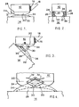
- FIG. 1 A simplified vertical section of the viewfinder 10, mounting arrangement 12 and part of the camera 14 is shown in figure 1.
- the viewfinder 10 has a viewing screen 16 partially surrounded by a hood 18 and onto which the image seen by the camera is projected. Projection of the camera image to the viewfinder viewing screen 16 is independent of angular displacements between the viewfinder 10 and the camera 14.
- the viewfinder 10 is attached to the camera 14 by the mounting arrangement 12.
- the mounting arrangement 12 comprises a pair of parallel spaced apart rockers 20 which are attached to the underneath of the viewder 10.
- Attachment means in the form of cables 24 prevent separation of the rockers 20 from the rocker support 22.
- the cables 24 are secured at respective ends of the rockers 20 and pass along the operational surface thereof so as to contact the corresponding rocker support 22.
- the cables 24 then pass in their respective directions along the rockers support 22 and are secured adjacently ends thereof.
- Each cable 24 is secured at one end of a rocker 20 and-the other end -of each cable is secured at the end of the corresponding rocker support 22 opposite the end of the rocker 20 at which the cable is secured.
- the cables 24 are tensioned by means of respective tension drums (not shown) at one or both ends of the cables.
- the rocker supports 22 have an arcuate longitudinal profile which act as tensioners and thereby reduce the tension required within the cables 24 themselves in order to retain the viewfinder 10 on the camera 14 with sufficent security.
- the rockers 20 each have a curved surface 26 which permits a rocking motion between the viewfinder 10 and the camera 14.
- the cables 24 pass along the surfaces 26 between the rockers 20 and rockers support 22. Due to the arcuate curve 26 of the rockers 20 and the arcuate profile of the rockers supports 22, the cables 24 cross each other along the length of the mounting arrangement 12 and in effect form a rolling pivot between the rockers 20 and the corresponding rockers supports 22. As the viewfinder 10 is tilted with respect to the camera 14 the rolling pivots formed by the cables 24 move along the length of the mounting arrangement 12.
- the curved surfaces 26 of the rockers 20 follow the perimeter of an ellipse and this configuration is found to be particularly beneficial for rocking of the viewfinder 10 with respect to the camera 14 and also for more extreme displacements between the viewfinder 10 and camera 14, as will be described.
- Figure 2 shows the viewfinder 10 and mounting arrangement 12 as seen from the front of the camera 14.
- Figure 2 shows that the rockers 20 are restrained between a pair of longitudinal guides 28 secured to the camera 14.
- the rocker supports 22 abut a respective guide 28 and are located between the guides 28.
- the guides 28 prevent lateral displacement of the viewfinder 10 relative to the camera 14 but have a hight which avoids fouling with the base of the viewfinder 10 throughout the entire range of possible movement as the viewfinder 10.
- FIG 3 The relative positions of the viewfinder 10 and camera 14 when the camera is inclined at a relatively large positive angle is illustrated by figure 3.
- the viewfinder 10 is substantially horizontal and this would be consistant with the camera being positioned five to six feet above the ground and in which the screen 16 is horizontally alinged with the operaters normal head hight.
- the angle of tilt between the viewfinder 10 and camera 14 becomes very large.
- the lateral restraint provided by the guides 28 is significantly reduced. More importantly retention of the viewfinder 10 at such a large tilt to the camera 14 would be very unstable.
- the mounting arrangement 12 includes a pair of pivotally connected struts 30 each strut of each pair also being pivotally retained on a respective side of the rocking motion.
- One-pivotal- connection is made to the viewfinder 10 and a further pivotal connection is made on the guide 28.
- the pivotal connections to the viewfinder 10 and/or to the guides 28 are provided with respective friction discs (not shown). The friction discs enable the ease with which the viewfinder 10 can be tilted to be adjusted and such. adjustment also effects the stability of the viewfinder when at large angles of tilt with respect of the camera 14.
- Figure 4 shows the mounting arrangement 12 on an enlarged scale as compared with figures 1 to 3.
- This addition consists of springs 32 connected between the viewfinder 10 and a respective pair of struts 30. The ends of the springs 32 are attached on opposite sides of the pivotal connection of the struts to the viewfinder 10.
- the additions of the spings 32 provides increased stability for the viewfinder 10 when at large angles of tilt to the camera 14.
- the springs 32 are of particular benefit when the weight of the viewfinder 10 is relatively high.
- a major advantage of the mounting arrangement of this invention is that the centre of gravity of the camera 14 and viewfinder 10 is less drastically effected by movment of the viewfinder 10 than is the case with conventional mounting arrangements. This advantage is very significant in practice.
- the necessity of separate operating and carring positions for the viewfinder 10 is obviated. Tilting movement of the viewfinder 10 is found to be particularly smooth and avoids flatspots which are often encountered throughout the movement of conventionally mounted vi ewfi nders.
Landscapes
- Engineering & Computer Science (AREA)
- General Engineering & Computer Science (AREA)
- Mechanical Engineering (AREA)
- Multimedia (AREA)
- Signal Processing (AREA)
- Physics & Mathematics (AREA)
- General Physics & Mathematics (AREA)
- Viewfinders (AREA)
- Accessories Of Cameras (AREA)
Applications Claiming Priority (2)
| Application Number | Priority Date | Filing Date | Title |
|---|---|---|---|
| GB8225699 | 1982-09-09 | ||
| GB08225699A GB2126823B (en) | 1982-09-09 | 1982-09-09 | Mounting arrangement for a camera viewfinder |
Publications (2)
| Publication Number | Publication Date |
|---|---|
| EP0106490A2 true EP0106490A2 (de) | 1984-04-25 |
| EP0106490A3 EP0106490A3 (de) | 1985-08-07 |
Family
ID=10532788
Family Applications (1)
| Application Number | Title | Priority Date | Filing Date |
|---|---|---|---|
| EP83305159A Withdrawn EP0106490A3 (de) | 1982-09-09 | 1983-09-06 | Befestigungsanordnung für einen Kamerasucher |
Country Status (4)
| Country | Link |
|---|---|
| US (1) | US4605296A (de) |
| EP (1) | EP0106490A3 (de) |
| JP (1) | JPS5989078A (de) |
| GB (1) | GB2126823B (de) |
Families Citing this family (6)
| Publication number | Priority date | Publication date | Assignee | Title |
|---|---|---|---|---|
| US4560129A (en) * | 1984-04-27 | 1985-12-24 | Rca Corporation | Tilting apparatus for a viewfinder of a camera |
| DE3520457A1 (de) * | 1985-06-07 | 1986-12-11 | Robert Bosch Gmbh, 7000 Stuttgart | Fernsehkamera mit einem elektronischen sucher |
| US5619302A (en) * | 1996-04-17 | 1997-04-08 | Xerox Corporation | Apparatus and method for scanning a bound document using a wedge shaped platen |
| TWI239425B (en) * | 2004-07-21 | 2005-09-11 | Benq Corp | Image capturing device |
| EP1638316A1 (de) * | 2004-09-15 | 2006-03-22 | Thomson Licensing | Kamera mit beweglichem Sucher |
| JP4174736B2 (ja) * | 2006-08-24 | 2008-11-05 | ソニー株式会社 | 撮像装置およびロック機構 |
Family Cites Families (12)
| Publication number | Priority date | Publication date | Assignee | Title |
|---|---|---|---|---|
| US1800225A (en) * | 1928-11-13 | 1931-04-14 | Mitchell Camera Corp | View-finder mounting for cameras |
| US2285456A (en) * | 1939-02-25 | 1942-06-09 | Roger L Nowland | Camera and finder |
| DE1917671C3 (de) * | 1969-04-05 | 1973-01-04 | Robert Bosch Fernsehanlagen Gmbh, 6100 Darmstadt | Fernsehkamera mit einem schwenkbar gelagerten elektronischen Sucher |
| GB1330491A (en) * | 1971-04-19 | 1973-09-19 | Vinten Ltd | Tiltable mounting |
| DE2216681B1 (de) * | 1972-04-07 | 1973-10-11 | Robert Bosch Fernsehanlagen Gmbh, 6100 Darmstadt | Tragbare Fernsehkamera |
| JPS4940907U (de) * | 1972-07-14 | 1974-04-10 | ||
| US3945053A (en) * | 1973-03-05 | 1976-03-23 | Purdue Research Foundation | Rolling contact prosthetic knee joint |
| JPS5737025Y2 (de) * | 1977-07-27 | 1982-08-16 | ||
| JPS56147436U (de) * | 1980-04-05 | 1981-11-06 | ||
| JPS56161620U (de) * | 1980-04-30 | 1981-12-01 | ||
| US4375653A (en) * | 1981-04-10 | 1983-03-01 | Ampex Corporation | Camera mount |
| US4408860A (en) * | 1982-04-02 | 1983-10-11 | Ampex Corporation | Apparatus for a camera mount |
-
1982
- 1982-09-09 GB GB08225699A patent/GB2126823B/en not_active Expired
-
1983
- 1983-09-06 EP EP83305159A patent/EP0106490A3/de not_active Withdrawn
- 1983-09-09 JP JP58167386A patent/JPS5989078A/ja active Pending
- 1983-09-09 US US06/530,988 patent/US4605296A/en not_active Expired - Fee Related
Also Published As
| Publication number | Publication date |
|---|---|
| GB2126823A (en) | 1984-03-28 |
| JPS5989078A (ja) | 1984-05-23 |
| US4605296A (en) | 1986-08-12 |
| GB2126823B (en) | 1986-05-14 |
| EP0106490A3 (de) | 1985-08-07 |
Similar Documents
| Publication | Publication Date | Title |
|---|---|---|
| US5435515A (en) | Adustable, iso-elastic support apparatus | |
| US4156512A (en) | Equipment support system | |
| US5908181A (en) | Support for cameras | |
| US20030201371A1 (en) | Support for hand held video camera | |
| USRE32213E (en) | Equipment for use with hand held motion picture cameras | |
| US4241894A (en) | Seat suspension apparatus | |
| EP0106490A2 (de) | Befestigungsanordnung für einen Kamerasucher | |
| US3273484A (en) | Camera supports | |
| US7137747B2 (en) | Shock and vibration isolator for a camera | |
| EP1887274A1 (de) | Filmkamerakopf | |
| JPH0515529A (ja) | 超音波診断装置のモニタ部保持装置 | |
| US5469793A (en) | Tiltable load supporting platforms | |
| US4365866A (en) | Light masking device | |
| US5218876A (en) | Control device for a tiltable mounting head | |
| GB1589062A (en) | Support structure | |
| KR102126327B1 (ko) | 배전케이블 스페이스 유지장치 | |
| GB1581990A (en) | Suspension for vehicles | |
| CN108528744A (zh) | 一种航拍摄像头减震机构 | |
| JPH04503240A (ja) | 傾斜可能な取付ヘッドのための制御装置 | |
| US3908953A (en) | Support apparatus for a seat | |
| US4606628A (en) | Video projector lens angulation mechanism | |
| KR20180055421A (ko) | 카메라 레벨링 장치 | |
| JPH10141588A (ja) | 小型カメラ用クレーン | |
| JP5005410B2 (ja) | カメラ用支持装置 | |
| FI59056C (fi) | Foer uppbaerande av ett fordonssaete avsedd anordning som innefattar ett stativ och ett av detta fjaedrande uppburet baerorgan foer ett saetes sits och ryggstoed |
Legal Events
| Date | Code | Title | Description |
|---|---|---|---|
| PUAI | Public reference made under article 153(3) epc to a published international application that has entered the european phase |
Free format text: ORIGINAL CODE: 0009012 |
|
| AK | Designated contracting states |
Designated state(s): AT BE CH DE FR GB IT LI LU NL SE |
|
| PUAL | Search report despatched |
Free format text: ORIGINAL CODE: 0009013 |
|
| AK | Designated contracting states |
Designated state(s): AT BE CH DE FR GB IT LI LU NL SE |
|
| 17P | Request for examination filed |
Effective date: 19850913 |
|
| 17Q | First examination report despatched |
Effective date: 19861028 |
|
| STAA | Information on the status of an ep patent application or granted ep patent |
Free format text: STATUS: THE APPLICATION IS DEEMED TO BE WITHDRAWN |
|
| 18D | Application deemed to be withdrawn |
Effective date: 19880331 |
|
| RIN1 | Information on inventor provided before grant (corrected) |
Inventor name: MUNNION, DEREK |