EP0105424B1 - Type wheel selection device for a printing system - Google Patents
Type wheel selection device for a printing system Download PDFInfo
- Publication number
- EP0105424B1 EP0105424B1 EP83109467A EP83109467A EP0105424B1 EP 0105424 B1 EP0105424 B1 EP 0105424B1 EP 83109467 A EP83109467 A EP 83109467A EP 83109467 A EP83109467 A EP 83109467A EP 0105424 B1 EP0105424 B1 EP 0105424B1
- Authority
- EP
- European Patent Office
- Prior art keywords
- franking
- adjusting
- push rod
- adjusting push
- setting mechanism
- Prior art date
- Legal status (The legal status is an assumption and is not a legal conclusion. Google has not performed a legal analysis and makes no representation as to the accuracy of the status listed.)
- Expired - Lifetime
Links
Images


Classifications
-
- G—PHYSICS
- G07—CHECKING-DEVICES
- G07B—TICKET-ISSUING APPARATUS; FARE-REGISTERING APPARATUS; FRANKING APPARATUS
- G07B17/00—Franking apparatus
- G07B17/00459—Details relating to mailpieces in a franking system
- G07B17/00508—Printing or attaching on mailpieces
-
- B—PERFORMING OPERATIONS; TRANSPORTING
- B41—PRINTING; LINING MACHINES; TYPEWRITERS; STAMPS
- B41J—TYPEWRITERS; SELECTIVE PRINTING MECHANISMS, i.e. MECHANISMS PRINTING OTHERWISE THAN FROM A FORME; CORRECTION OF TYPOGRAPHICAL ERRORS
- B41J7/00—Type-selecting or type-actuating mechanisms
- B41J7/48—Type carrier arrested in selected position by electromagnetic means
-
- G—PHYSICS
- G07—CHECKING-DEVICES
- G07B—TICKET-ISSUING APPARATUS; FARE-REGISTERING APPARATUS; FRANKING APPARATUS
- G07B17/00—Franking apparatus
- G07B17/00185—Details internally of apparatus in a franking system, e.g. franking machine at customer or apparatus at post office
- G07B17/00314—Communication within apparatus, personal computer [PC] system, or server, e.g. between printhead and central unit in a franking machine
- G07B2017/00354—Setting of date
-
- G—PHYSICS
- G07—CHECKING-DEVICES
- G07B—TICKET-ISSUING APPARATUS; FARE-REGISTERING APPARATUS; FRANKING APPARATUS
- G07B17/00—Franking apparatus
- G07B17/00459—Details relating to mailpieces in a franking system
- G07B17/00508—Printing or attaching on mailpieces
- G07B2017/00516—Details of printing apparatus
- G07B2017/00524—Printheads
- G07B2017/00548—Mechanical printhead
Definitions
- the invention relates to an adjusting device for type wheels with the features of the preamble of claim 1 and a franking machine with at least one adjusting device according to claim 1.
- the franking machines currently in use e.g. B. with the type designation "FRAMA Mod. 100 electronic" of the applicant have an adjustment device for each type wheel, which is composed of numerous and complex to manufacture and assemble individual parts.
- Each setting device has a toothed rack which extends in the longitudinal direction through the drive shaft of the franking head and which engages on the one hand with the gearwheel of the type wheel and on the other hand with a gearwheel gear of an adjusting disk rotating with the shaft.
- a manually operated adjusting lever is brought into engagement with the adjusting disc and swiveled by an angle corresponding to the numerical value.
- This pivoting movement causes a displacement of the rack and thus a rotation of the type wheel into the desired setting position via the gearwheel gear arranged in the adjusting disc.
- the setting position in the adjusting disc is secured by locking means.
- the adjusting disc is provided with mechanical means which mechanically actuate a mechanical counter each time the franking head and thus also the steep disc is rotated, which counts the value units used during franking. Details of the mechanics used are e.g. B. the spare parts catalog belonging to the above machine type.
- a setting device for type wheels of a printing device with the features of the preamble of claim 1 is known from US-A-3 822 640. From this document it is known to rotate the respective type wheel for a printing device with stationary, rotatably mounted type wheels by means of two ratchet levers mounted on a swivel plate into the desired printing position. These ratchet levers are held in constant engagement with the driving ratchet wheel by spring force. Their pushing adjusting movement results from the back and forth swiveling movement of this swivel plate, which is coupled to two electromagnets arranged opposite to each other.
- the invention has for its object to find an adjusting device for type wheels of a printing device, the type wheels can perform a circular movement during printing, so that they can be provided on the circumference of a rotating printing roller or the franking head of a franking machine.
- the setting device should be compared with z. B. by LU-A-83 626 or US-A-4 050 374 known adjusting devices are easier to manufacture and assemble by mechanically simpler structure. This object is achieved according to the invention on the basis of the features of patent claim 1.
- a preferred combination of the setting device according to the invention with a franking machine is the subject of patent claim 5.
- a housing part of the franking machine is indicated by dashed lines 2, which is located on the side of a main housing, not shown, and includes the franking head 4.
- the general structure of a franking machine is assumed to be known. An example shows the commonly used machine of the applicant with the designation "FRAMA Mod. 100 electronic".
- the franking head is located above a franking table 6, over which envelopes are moved in the direction of the arrow 7 for printing with the franking value and the date.
- the franking head 4 rotates in accordance with the working cycle of the franking machine, triggered by a contact 9 arranged in the franking table and actuated by feeding an envelope, so that the cliché 8 for the franking value and the cliché 10 for the date roll on the envelope, not shown .
- the pressure is generated by the automatic stroke movement of the pressure roller 12 indicated by a dashed line.
- the stroke movement results from a lever movement of a drive transmission, not shown, which is caused by the rolling of a control roller 13 indicated by dashed lines in FIG. 5 on a control curve 15 of the control wheel 17 ( Fig. 12) is triggered.
- Dye is transferred to plates 8 and 10 by a rolling movement through an ink storage roller, not shown.
- a corresponding device is the subject of EP-A 0 064 125.
- a first example of use of the setting device according to the invention on a franking machine, shown in FIGS. 1 to 4, relates to the adjustment of the type wheels of the date plate 10 by the setting devices 14, 14 'acting from the circumference of the franking head.
- the setting device for the type wheels 18 to 21 of the date plate 10, which are shown enlarged in FIG. 4, has an input device 24 which has a plurality of switching buttons 25 which are used at the same time for setting the numbers of an electronic date display 26.
- An actuation of a switch button 25 triggers an electrical pulse, which is supplied via lines 28, 29 to both the date display 26 and the electromechanical actuation device 14 for the type wheels 18 to 21, as is shown schematically in FIG. 1 by a circuit.
- the adjusting device 14, 14 ' has an adjusting plunger 30, 32, or 30', 32 'for each type wheel to be adjusted. As shown in FIGS. 2 and 3, an adjusting device 14, 14 'can be provided on both sides of the date plate 10 or the franking head 4. Since these setting devices 14, 14 'can be designed identically, only the actuating device 14 is described below.
- the adjusting device has a z. B. vertically directed mounting plate 34, the z. B. is rigidly attached by means of screws 35 to an inner wall 39 of the franking machine located next to the franking head.
- This mounting plate 34 carries at least two and, in the present example, three electromagnets 36 to 38.
- the electromagnets 36, 37 serve to actuate the adjusting plungers 32, 30 and are fastened in parallel to one another directly on the mounting plate.
- the third electromagnet 38 is fastened to a bend 40 bent out perpendicularly from the mounting plate and thus directed perpendicular to the other electromagnets 36, 37.
- This third electromagnet 38 serves to pivot a guide plate 42, on which the adjusting slides 30, 32 slide, into a position in which the adjusting plungers 30, 32 engage with a gear 44, 45 for adjusting a type wheel 20 or 18 can reach.
- This guide plate 42 has a rectangular shape in side view (FIG. 2), with its shorter leg 43 running parallel to the mounting plate 34 and carrying a tension spring 47 at its free end, the other end of which is attached to the bend 40 of the mounting plate 34.
- the tension spring 47 thus holds the guide plate 42 in the waiting position shown in FIG. 2, in which the adjusting plungers 30, 32 are held at a distance from the franking head 4, so that the franking head 4 can rotate freely for franking.
- the third electromagnet 38 is provided, which pulls the longer leg 46 or its fork leg 49 (FIG. 3) downward against the tensile force of the return spring 47, so that with the guide plate 42, the adjusting plungers 30, 32 move into a pivoting position in which they can turn the adjusting wheel 44, 45 of a type wheel after longitudinal displacement by means of the electromagnets 36, 37.
- the electromagnets 36, 37 have an armature shaft 54, 55 which extends through the magnet winding and at one end of which the angled leg 58 of the associated adjusting plunger 30 and 32 is articulated.
- the armature shaft 54, 55 moves against the force of a tension spring 56, 57 fastened at one end thereof and thus pushes the adjusting plunger 30 or 32 forward in the direction of the rotary movement of the gear wheel 44 or 45.
- the articulated connection 60 between the anchor shaft 54 or 55 and the angled leg 58 of the adjustment plunger enables the pivoting movement of the adjustment plunger 30, 32 together with the guide plate 42.
- the adjustment plungers 30, 32 For the lateral guidance of the adjustment plungers 30, 32 on the guide plate 42, the latter is provided with an obliquely upwardly bent front end 62 and in its central region with a vertically upwardly bent plate part 64, in each of which there is a slot 65 to 68, which includes the adjusting plunger 30 or 32 stamped from a sheet metal part.
- the part 64 bent upwards at right angles from the guide plate 42 also serves as a stop for the longitudinal stroke movement of the adjusting plungers, in that they have a stop bolt 70, 71.
- a sliding cam 72 is formed on the underside of the adjusting plungers 30, 32, with which the adjusting plungers 30, 32 slide on the upper side of the guide plate 42.
- a small cover plate 74 is fastened at this point by means of a bolt 75 at a distance from the guide plate.
- the electromagnets 38 and 36 must be excited.
- the excitation current is triggered by depressing one of the switching buttons 25 (FIG. 1).
- the unit consisting of the guide plate 42 and the adjustment plunger 30, 32 first pivots downward and thus also the tip 78 of the adjustment plunger 30, 32 intended for engagement in the gearwheel 44 until the latter reaches a plane which corresponds to the pitch circle of the gearwheel 44 or 45 affects.
- the adjustment plunger 32 moves forward, so that the adjustment tip 78 engages in a tooth of the gearwheel and the gearwheel 44 rotates further by a certain angle with the type wheel 20 firmly connected to it.
- the type wheels 18 to 21 are coupled to an adjustment gear, to which an adjustment plunger is assigned, while the type wheel 80 has no adjustment gear for the setting of the 10s, since the adjustment to be carried out every 10 years
- Gear wheel is expediently carried out by hand using a pointed tool after a closing flap is opened in the housing of the franking machine and is located in the region of the franking head.
- an automatic triggering can also be carried out by means of a battery-operated clock with a date display.
- the adjusting device is preferably fastened in an adjustable manner in the circumferential direction relative to the franking head.
- the position of the adjusting plungers 30, 32 can be exactly aligned again with the adjusting gearwheels 44, 45 after the plate 10 has been exchanged for a different type of plate.
- the use of various clichés, e.g. B. on a franking machine, is otherwise the same construction of the franking machine is required to make an adjustment to changing needs, z. B. if the franking machine has to be adjusted at a different location or in a different country with different wishes or regulations when franking. It is possible for the group of date type wheels on the franking head to assume a different position in the circumferential direction.
- the adjustment of the adjusting device 14, 14 ' can be achieved in a simple manner by the screws 35, which attach the mounting plate 34 to the inner wall 39 of the franking machine, extending through an elongated opening 81 which either extends into the inner wall of the franking machine or are in the mounting plate, so that the screw can assume 81 different clamping positions in this opening.
- an actuating mechanism for the adjustment of the setting device 14, 14 'relative to the franking head in the circumferential direction, an actuating mechanism, not shown, which is actuated by hand or by a drive and can be provided with an electronic control, can also be used.
- Such an actuating mechanism makes it possible to adjust the actuating device in the circumferential direction relative to the franking head in such a wide range that the same adjusting device can be used by a plurality of clichés 8, 10 for the actuation of the type wheels or their gear wheels by appropriate movement in the circumferential direction . 1, such an adjusting mechanism can move the adjusting device 14 from the position shown in FIG. 1 over the plate 10 to a position in which it is above the plate 8.
- the guidance of this circumferential movement of the adjusting device can in a slot concentric with the circumference of the franking head, by guide rails, and the like. The like.
- the second cliché is the type wheels corresponding to the franking value has, so special measures are to be taken so that it is prevented that these type wheels, z. B. can be set from outside using an instrument in an unauthorized manner.
- mechanical rotation of the franking head when the franking machine was not switched on electrically would enable a value to be withdrawn or franked without the franking value being counted in the electronic memory provided for such a machine for the value units used.
- each adjusting device has a device part which is identical to one of the adjusting devices 14, 14 'described in the foregoing, corresponding to the illustrations in FIGS. 1 to 3, however, in contrast to an adjusting device 14, each adjusting device additionally has a rack-and-pinion slide valve 83 to 86 , which is arranged mechanically between the adjusting gear 88 of a type wheel and an adjusting plunger 89 or 90.
- the adjustment plungers 89, 90 correspond to the adjustment plungers 30, 32 and 30 ', 32' of the previously described setting devices 14, 14 'and are therefore only partially shown in FIG. 5.
- the adjusting slides 83 to 86 are guided in the shaft 16 of the franking machine. For this purpose, this has outwardly open guide slots 92 to 95, as can best be seen in FIG. 9.
- the numerical value is not entered in the display 26 directly by the electrical pulse triggered when the switch button 25 is depressed, but rather by the pulse of a photocell 98 which can be swiveled in the swivel range of about an axis 100
- Latches 101, 102 is arranged. There is a latch 101, 102, or 101 ', 102' for each of the adjusting slides 83 to 86, as the illustration in FIG. 5 shows. These overlap in the view according to FIG. 9, so that only a pair 101, 102 can be seen there.
- FIG. 9 shows the latches 101, 102, in the locked position, in that the area 103 is locked in the tooth space of the adjusting slide 84 and the area 104 of the locking lever 102 is locked in the tooth gap 105 of the adjusting slide 85.
- the adjustment plunger 89 pushes the associated adjustment slide further by one tooth, the pawl region 103 or 104 sliding over the sawtooth-shaped tooth 97, so that the latching lever 101, 102 executes a pivoting movement which leads to a temporary blocking the photocell 98 leads.
- This causes electronic feedback to the display register, which corresponds to register 26 in FIG. 1, which adds one digit to the previous numerical value.
- the photocell pair 98, 99 can thus electronically determine each position of the two latches 101, 101 'and 102, 102' arranged one above the other according to FIG. 9, so that the mechanical movement carried out is electronically confirmed.
- the secure latching of the latching levers is ensured by a tension spring 111, which connects the legs of the latching pawls 101, 102 to one another.
- the axes 100 of the latches 101, 102, 101 ', 102' are attached to the steering wheel 17, so that the latches rotate together with the steering wheel and the machine shaft 16 when franking.
- the side view of the steering wheel 17 shown on a smaller scale in FIG. 10 shows fastening holes 112 for fastening these axles 100.
- the area of the latches 101, 102 facing the machine shaft 16 is adapted outside the area of the adjusting slide to the shape of the shaft and engages in a circumferential groove 113 of the shaft, as shown in FIG. 9, so that the latches in this groove 113 are supported against lateral deflection in the direction of the shaft.
- the shaft 16 of the franking machine always takes exactly the same rotational position for the setting of the type wheels must, so that the arranged above and below the shaft and not rotating adjusting plunger 89, 90 can always be brought exactly into engagement with the teeth 97 of the associated adjusting slide 83 to 86.
- the shaft 16 and thus the franking head 4 are driven by the engagement of a drive pinion (not shown) in the ring gear 115 on the circumference of the control wheel 17.
- This pinion is driven by an electric motor (not shown) until the control wheel has made a 360 ° revolution.
- the shading of the electric motor driving the pinion is carried out in the usual way by a contact switch of a second control wheel, not shown, on the right end of the shaft 16.
- the pressure lever 120 of the control roller 17 is secured in the locking position shown in FIG. 10 by a pawl 122 by pulling it into the locking position by a spring 123. However, if there is a connection between the franking machine and the voltage source, an electromagnet 124 pulls the pawl into a release position.
- the control wheel 17 is driven again, so that the control roller 117 moves past the highest point 125 of the control curve 116 following the indentation 118 and the pressure lever 120 counteracts the force of the tension spring 119 about the axis 126 swings back.
- an anti-rebound pawl 128, indicated by broken lines in FIG. 12, is present, which extends over a ratchet tooth 129 moved and clicks behind it into the position shown.
- the direction of rotation of the steering wheel is indicated by an arrow 130 in FIGS. 10 and 12.
- the franking machine also has a device for mechanically locking the franking value, which has been set by moving the adjusting slides 83 to 86.
- This locking device comes into effect as soon as the shaft 16 has rotated through a small angle and is only released again when the set franking value is to be deleted again.
- two pawls 135, 136 are provided, which are provided for engaging the tooth spaces 137 of a rectangular toothing 138 of the adjusting slides 83 to 86 and are in engagement with a tooth space 137 in the representations corresponding to FIGS. 5 and 13.
- This rectangular toothing 138 is arranged in the longitudinal direction of the adjusting slide behind the row of adjusting teeth 97 and the tooth-free area 109, as also shown in FIGS. 6 and 7.
- Each pawl 135, 136 is used to block a similarly shaped adjusting slide 83, 85 or 84, 86, in that the pawl 135 for engaging in the rectangular toothing 138 of the adjusting slide 83, 85 and the pawl 136 for engaging in the rectangular toothing of the blocking slide 84, 86 is provided.
- 6 and 7 the toothings of which extend in opposite directions from the shaft axis in the sliding assembly 140, 141 extending through the shaft 16, since they are used for the adjustment by adjusting plungers arranged on opposite sides of the shaft 16 89, 90 are provided, as is also true for the latches 101, 102 according to FIG. 9.
- the pawls 135, 136 do not rotate with the control disk 17, but are pivotably mounted about a common fixed axis 142 in a wall of the machine housing.
- Each pawl 135, 136 has a control pin 143, 144, which are guided in a control groove 137, which is shown in FIG. 5 on the left side of the steering wheel 17 and is shown with its course in FIG. 12.
- the control disk rotates, the control pins 143, 144 and thus the pawls 135, 136, based on the machine shaft 16, are pulled radially inward into the respective tooth gap 137 corresponding to the setting position of the adjusting slide, and into an annular groove 150 of the shaft 16.
- the engagement edge 151, 152 of the pawls is designed in the shape of a circular arc. This engagement of the pawls in the groove 150 supports them against bending in the direction of the shaft 16. In the engaged position, the pawls 135, 136 are locked by a locking lever 154.
- This locking lever 154 is pivoted about a fixed axis 156 into engagement position with the pawls by a tension spring 155, in which two extensions 157, 158 of the pawls are held in a recess 160 of the locking lever 154.
- pawls 135, 136 remain in the locking position shown in FIGS. 5 and 13, so that the franking value set remains secured for several frankings with the same value. Only after initiation of the deletion process for the set franking value does the locking lever 154 release the pawls 135, 136 again by an electromagnet 161 pivoting the locking lever 144 back against the force of the spring 155. In the setting position of the shaft 16, the pawls 135, 136 can then move apart again by the tension of the springs 148, 149 in order to enable a new setting of the type wheels or franking values.
- the latches 101, 102, 101 ', 102' are also to be moved out of engagement with the teeth 97 of the advance slides 83 to 86, for which purpose a release lever 163 is provided, which is actuated by means of an electromagnet 164 against each lever arm 165 , 166 of the pawls 101, 102 presses, so that the pawls pivot against the force of the tension spring 111 about their axis 100 outwards.
- the tension springs 106 provided on each of these slides pull the adjustment slides back into their starting position, i.e. 5 to the right until they reach the position shown there.
- the edge 168 on the head part 169 of the adjusting slide comes into abutment with the end face 170 of the machine shaft 16.
- the latches 101, 102 are optically read by means of the photocells 98, 99 in order to determine whether all the racks are in the starting or zero position. If this is not the case, the deletion process is initiated, i.e. solenoids 161 and 164 are actuated to release pawls 135, 136 and pawls 101, 102.
- FIG. 5 shows one of two bearings 172 which is connected to an inner housing wall 173 of the franking machine by means of screws 174.
- the pawls 135, 136 and the Versteibtösset 89, 90 all parts shown in FIG. 5 perform the rotary movement together with the shaft 16 when franking.
- the photocells 98, 99 shown in FIG. 9 are also arranged in a fixed manner, since the optical reading of the position of the latches 101, 102 takes place only in the setting position of the shaft 16.
- setting devices 14, 14 'of the same design are used in a plurality on one franking machine, so that the production in series production is considerably simplified.
- an adjusting device 14, 14 ' each with two adjusting rams 30, 32; are for setting the date or for setting the cliché 10 on both sides of the franking head.
Abstract
Description
Die Erfindung betrifft eine Einstellvorrichtung für Typenräder mit den Merkmalen des Oberbegriffs des Patentanspruchs 1 sowie eine Frankiermaschine mit mindestens einer Einstellvorrichtung nach Patentanspruch 1.The invention relates to an adjusting device for type wheels with the features of the preamble of
Die zur Zeit gebräuchlichen Frankiermaschinen, z. B. mit der Typenbezeichnung "FRAMA Mod. 100 electronic" der Anmelderin haben für jedes Typenrad eine Einstellvorrichtung, die aus zahlreichen und aufwendig herzustellenden sowie zu montierenden Einzelteilen zusammengesetzt ist. Jede Einstellvorrichtung hat eine sich durch die Antriebswelle des Frankierkopfes in Längsrichtung erstreckende Zahnstange, die einerseits mit dem Zahnrad des Typenrades und andererseits mit einem Zahnradgetriebe einer sich mit der Welle drehenden Stellscheibe in Eingriff steht. Beim Einstellen des Typenrades wird ein von Hand zu betätigender Einstellhebel in Eingriff mit der Stellscheibe gebracht und um einen dem Zahlenwert entsprechenden Winkel geschwenkt. Diese Schwenkbewegung bewirkt über das in der Stellscheibe angeordnete Zahnradgetriebe eine Verschiebung der Zahnstange und damit eine Verdrehung des Typenrades in die gewünschte Einstellposition. Nach Lösen des Eingriffs zwischen der Stellscheibe und dem Einstellhebel wird die Einstellposition in der Stellscheibe durch Rastmittel gesichert. Weiterhin ist die Stellscheibe mit mechanischen Mitteln versehen, die auf mechanische Weise bei jeder Umdrehung des Frankierkopfes und damit auch der Steilscheibe ein mechanisches Zählwerk betätigen, das die beim Frankieren verbrauchten Werteinheiten zählt. Einzelheiten über die verwendete Mechanik sind z. B. dem zu obengenanntem Maschinentyp gehörigen Ersatzteilkatalog zu entnehmen.The franking machines currently in use, e.g. B. with the type designation "FRAMA Mod. 100 electronic" of the applicant have an adjustment device for each type wheel, which is composed of numerous and complex to manufacture and assemble individual parts. Each setting device has a toothed rack which extends in the longitudinal direction through the drive shaft of the franking head and which engages on the one hand with the gearwheel of the type wheel and on the other hand with a gearwheel gear of an adjusting disk rotating with the shaft. When setting the type wheel, a manually operated adjusting lever is brought into engagement with the adjusting disc and swiveled by an angle corresponding to the numerical value. This pivoting movement causes a displacement of the rack and thus a rotation of the type wheel into the desired setting position via the gearwheel gear arranged in the adjusting disc. After loosening the engagement between the adjusting disc and the adjusting lever, the setting position in the adjusting disc is secured by locking means. Furthermore, the adjusting disc is provided with mechanical means which mechanically actuate a mechanical counter each time the franking head and thus also the steep disc is rotated, which counts the value units used during franking. Details of the mechanics used are e.g. B. the spare parts catalog belonging to the above machine type.
Durch die LU-A-83 626 oder die US-A-4 050 374 wurde bereits vorgeschlagen, die mechanische Stellbewegung elektromotorisch vorzunehmen, jedoch hat dies durch die Verwendung von Stellmotoren zu einer noch aufwendigeren und voluminöseren Mechanik geführt. Die Verwendung elektrischer Antriebe hat jedoch den Vorteil, dass die Eingabe der Stellwerte elektronisch erfolgen kann, z. B. auch in Abhängigkeit vom elektrischen Signal einer Wiegeeinrichtung, da der einzustellende Frankierwert auch vom Gewicht des zu frankierenden Briefes o. dgl. abhängig ist. Die elektronische Eingabe der Stellpositionen für die Typenräder hat auch den Vorteil, dass die Anzahl der durch das Frankieren verbrauchten Werteinheiten anstatt in einem mechanischem Zählwerk in einem elektronischen Zählwerk mit geringerem Aufwand gespeichert werden kann.It has already been proposed by LU-A-83 626 or US-A-4 050 374 to carry out the mechanical actuating movement by means of an electric motor, but this has led to an even more complex and voluminous mechanism through the use of servomotors. However, the use of electric drives has the advantage that the input of the control values can take place electronically, e.g. B. also in dependence on the electrical signal of a weighing device, since the franking value to be set also depends on the weight of the letter to be franked or the like. The electronic input of the positioning positions for the type wheels also has the advantage that the number of value units consumed by franking can be stored in an electronic counter with less effort instead of in a mechanical counter.
Durch die bekannten, rein mechanischen Einstellvorrichtungen für Typenräder an einer Frankiermaschine ist es mit vertretbarem Aufwand nur möglich, Typenräder nur eines Druckklischees einzustellen. Das am Umfang des Frankierkopfes üblicherweise vorgesehene zweite Druckklischee für das Datum muß jedoch nach Öffnen einer Gehäuseklappe von Hand mittels eines Werkzeuges verstellt werden.Due to the known, purely mechanical setting devices for type wheels on a franking machine, it is only possible with reasonable effort to set type wheels of only one printing plate. However, the second printing cliché for the date usually provided on the circumference of the franking head must be adjusted by hand after opening a housing flap using a tool.
Eine Einstellvorrichtung für Typenräder einer Druckeinrichtung mit den Merkmalen des Oberbegriffs des Patentanspruchs 1 ist aus der US-A-3 822 640 bekannt geworden. Aus dieser Druckschrift ist es bekannt, für eine Druckeinrichtung mit stationär drehbar gelagerten Typenrädern das jeweilige Typenrad durch zwei an einer Schwenkplatte gelagerte Klinkenhebel in die gewünschte Druckposition zu drehen. Diese Klinkenhebel werden durch Federkraft in ständigem Eingriff mit dem antreibenden Klinkenrad gehalten. Ihre schiebende Stellbewegung ergibt sich durch die hin- und herschwenkende Bewegung dieser Schwenkplatte, die mit zwei zueinander entgegengesetzt angeordneten Elektromagneten gekoppelt ist. Eine vergleichbare Druckeinrichtung, bei der der Klinkenhebel anstatt über eine Schwenkplatte über einen von nur einem Elektromagneten bewegten Zwischenhebel in Antriebsrichtung deschoben wird, ist durch die US-A 3 916 785 bekannt. Solche Druckeinrichtungen sind durch den ständigen Eingriff ihrer Klinkenhebel nicht für die Anordnung an einer rotierenden Druckwalze oder an dem Frankierkopf einer Frankiermaschine geeignet.A setting device for type wheels of a printing device with the features of the preamble of
Der Erfindung liegt die Aufgabe zugrunde, eine Einstellvorrichtung für Typenräder einer Druckeinrichtung zu finden, deren Typenräder beim Drucken eine Kreisbewegung ausführen können, so dass sie am Umfang einer rotierenden Druckwalze oder des Frankierkopfes einer Frankiermaschine vorgesehen sein können. Dabei soll die Einstellvorrichtung im Vergleich mit z. B. durch die LU-A- 83 626 oder die US-A-4 050 374 bekannten Einstellvorrichtungen durch mechanisch einfacheren Aufbau leichter herzustellen und zu montieren sein. Die Lösung dieser Aufgabe erfolgt erfindungsgemäß aufgrund der Merkmale des Patentanspruchs 1. Eine bevorzugte Kombination der erfindungsgemäßen Einstellvorrichtung mit einer Frankiermaschine ist Gegenstand des Patentanspruchs 5.The invention has for its object to find an adjusting device for type wheels of a printing device, the type wheels can perform a circular movement during printing, so that they can be provided on the circumference of a rotating printing roller or the franking head of a franking machine. The setting device should be compared with z. B. by LU-A-83 626 or US-A-4 050 374 known adjusting devices are easier to manufacture and assemble by mechanically simpler structure. This object is achieved according to the invention on the basis of the features of
Im folgenden wird die Erfindung anhand von in den Zeichnungen dargestellten Ausführungsbeispielen näher erläutert. Es zeigen:
- Fig. 1 eine Seitenansicht einer Frankiermaschine im Bereich des Frankierkopfes mit einer stirnseitigen Ansicht einer Einstellvorrichtung für zwei Typenräder in schematischer Darstellung,
- Fig. 2 eine Seitenansicht der Einstellvorrichtung und eines Teiles des teilweise geschnitten dargestellten Frankierkopfes,
- Fig. 3 eine Aufsicht auf die Einstellvorrichtung nach Fig. 2, den Frankierkopf,
- Fig. 4 eine vergrößerte Darstellung einer Gruppe von Typenrädern mit ihren Zahnrädern, mit teilweise dargestellten Verstellstösseln von zwei Einstellvorrichtungen,
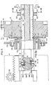
- Fig. 5 einen Teilschnitt durch eine Frankiermaschine entlang der Maschinenwelle im Bereich des Steuerrades und des Frankierkopfes mit eingezeichneter Querschnittsdarstellung der Welle entsprechend Fig. 5a,
- Fig. 6 und Fig. 7 zwei der Verstellschieber für die Einstellung der Frankierwerte der Frankiermaschine nach Figur 5,
- Fig. 8 eine Stirnansicht der in Figur 5 gezeigten Welle sowie von Verstellschiebern nach
Figur 6 und 7, - Fig. 9 einen Querschnitt durch die Frankiermaschinenwelle an der Stelle IX - IX der Figur 5 mit einem Rastklinkenpaar, jedoch in eingerasteter Position,
- Fig. 10 eine rechte Seitenansicht des Steuerrades nach Figur 5 mit eingerastetem Nullstellrasthebel,
- Fig. 11 einen Axialschnitt durch das Steuerrad nach
Figur 10, - Fig. 12 eine linke Seitenansicht des Steuerrades nach Figur 11 und
- Fig. 13 einen Querschnitt entlang der Linie XIII - Xlll der Figur 5 mit einem Sperrklinkenpaar.
- 1 is a side view of a franking machine in the area of the franking head with a front view of an adjusting device for two type wheels in a schematic representation,
- 2 is a side view of the setting device and a part of the franking head shown partially in section,
- 3 shows a top view of the setting device according to FIG. 2, the franking head,
- 4 is an enlarged view of a group of type wheels with their gear wheels, with adjusting rams of two adjusting devices, partially shown,
- Fig. 5 shows a partial section through a franking machine machine along the machine shaft in the area of the steering wheel and the franking head with the cross-sectional representation of the shaft shown in FIG. 5a,
- 6 and FIG. 7 two of the adjusting slides for setting the franking values of the franking machine according to FIG. 5,
- 8 shows an end view of the shaft shown in FIG. 5 and of adjusting slides according to FIGS. 6 and 7,
- 9 shows a cross section through the franking machine shaft at point IX-IX of FIG. 5 with a pair of latches, but in the engaged position,
- 10 shows a right side view of the steering wheel according to FIG. 5 with the zero-setting latch lever engaged,
- 11 shows an axial section through the steering wheel according to FIG. 10,
- Fig. 12 is a left side view of the steering wheel of Figure 11 and
- 13 shows a cross section along the line XIII-XII of FIG. 5 with a pair of pawls.
In Fig. 1 ist ein Gehäuseteil der Frankiermaschine durch Strichlinien 2 angedeutet, der sich seitlich von einem nicht dargestellten Hauptgehäuse befindet und den Frankierkopf 4 einschliesst. Der allgemeine Aufbau einer Frankiermaschine wird als bekannt vorausgesetzt. Ein Beispiel zeigt die vielfach verwendete Maschine der Anmelderin mit der Bezeichnung "FRAMA Mod. 100 electronic". Der Frankierkopf befindet sich oberhalb eines Frankiertisches 6, über den in Richtung des Pfeiles 7 Briefumschläge zum Bedrucken mit dem Frankierwert und dem Datum bewegt werden. Dabei dreht sich der Frankierkopf 4 entsprechend dem Arbeitszyklus der Frankiermaschine, ausgelöst durch einen im Frankiertisch angeordneten und durch die Zuführung eines Briefumschlages betätigten Kontaktschafters 9, so dass sich das Klischee 8 für den Frankierwert und das Klischee 10 für das Datum auf dem nicht dargestellten Briefumschlag abwälzen. Der Andruck erfolgt dabei durch die automatische Hubbewegung der durch eine Strichlinie angedeuteten Andruckwalze 12. Die Hubbewegung ergibt sich durch eine Hebelbewegung einer nicht dargestellten Antriebsübertragung, die durch die Abwälzung einer in Fig. 5 durch Strichlinien angedeuteten Steuerrolle 13 auf einer Steuerkurve 15 des Steuerrades 17 (Fig. 12) ausgelöst wird. Durch eine nicht dargestellte Farbspeicherwalze wird Farbstoff durch eine Abwälzbewegung auf die Klischees 8 und 10 übertragen. Eine entsprechende Einrichtung ist Gegenstand der EP-A 0 064 125.In Fig. 1, a housing part of the franking machine is indicated by dashed lines 2, which is located on the side of a main housing, not shown, and includes the franking head 4. The general structure of a franking machine is assumed to be known. An example shows the commonly used machine of the applicant with the designation "FRAMA Mod. 100 electronic". The franking head is located above a franking table 6, over which envelopes are moved in the direction of the arrow 7 for printing with the franking value and the date. The franking head 4 rotates in accordance with the working cycle of the franking machine, triggered by a
Ein erstes, in den Fig. 1 bis 4 dargestelltes Anwendungsbeispiel der erfindungsgemässen Einstellvorrichtung an einer Frankiermaschine betrifft die Verstellung der Typenräder des Datumklischees 10 durch die vom Umfang des Frankierkopfes her einwirkenden Einstellvorrichtungen 14, 14'.A first example of use of the setting device according to the invention on a franking machine, shown in FIGS. 1 to 4, relates to the adjustment of the type wheels of the
Die Einstellvorrichtung für die Typenräder 18 bis 21 des Datumklischees 10, die in Fig. 4 vergrössert dargestellt sind, hat eine Eingabevorrichtung 24, die mehrere Schalttasten 25 aufweist, die gleichzeitig der Einstellung der Zahlen einer elektronischen Datumsanzeige 26 dienen. Eine Betätigung einer Schalttaste 25 löst einen elektrischen Impuls aus, der über Leitungen 28, 29, sowohl der Datumsanzeige 26 als auch der elektromechanischen Betätigungsvorrichtung 14 für die Typenräder 18 bis 21 zugeführt wird, wie in Fig. 1 schematisch durch einen Schaltkreis dargestellt ist.The setting device for the
Die Einstellvorrichtung 14, 14' hat für jedes zu verstellende Typenrad jeweils einen Verstellstössel 30, 32, bzw. 30', 32'. Wie die Fig. 2 und 3 zeigen, können beidseitig des Datumklischees 10 bzw. des Frankierkopfes 4 jeweils eine Einstellvorrichtung 14, 14' vorgesehen sein. Da diese Einstellvorrichtungen 14, 14' identisch ausgeführt sein können, wird im folgenden nur die Betätigungsvorrichtung 14 beschrieben.The adjusting
Die Einstellvorrichtung hat eine z. B. vertikal gerichtete Halterungsplatte 34, die z. B. mittels Schrauben 35 an einer neben dem Frankierkopf befindlichen Innenwand 39 der Frankiermaschine starr befestigt ist. Diese Halterungsplatte 34 trägt mindestens zwei und im vorliegenden Beispiel drei Elektromagnete 36 bis 38. Die Elektromagnete 36, 37 dienen der Betätigung der Verstellstössel 32, 30 und sind parallel zueinander unmittelbar an der Hatterungsptatte befestigt. Der dritte Elektromagnet 38 ist an einer senkrecht aus der Halterungsplatte herausgebogenen Abwinkelung 40 befestigt und somit senkrecht zu den anderen Elektromagneten 36, 37 gerichtet. Dieser dritte Elektromagnet 38 dient dazu, eine Führungsplatte 42, auf der die Verstellschieber 30, 32 gleiten, in eine Position zu schwenken, in der die Verstellstössel 30, 32 mit einem Zahnrad 44, 45 für die Verstellung eines Typenrades 20 bzw. 18 in Eingriff gelangen können. Diese Führungsplatte 42 hat in Seitenansicht (Fig. 2) eine rechtwinklige Form, wobei ihr kürzerer Schenkel 43 parallel zur Halterungsplatte 34 verläuft und an seinem freien Ende eine Zugfeder 47 trägt, deren anderes Ende an der Abwinklung 40 der Halterungsplatte 34 befestigt ist. Die Zugfeder 47 hält somit die Führungsplatte 42 in der in Fig. 2 dargestellten Warteposition, in der die Verstellstössel 30, 32 in Abstand von dem Frankierkopf 4 gehalten werden, so dass dieser sich zum Frankieren unbehindert drehen kann. Der längere der Führung dienende Schenkel 46 der Führungsplatte 42 ist entsprechend der Darstellung in Fig. 3 gegabelt, und die Enden beider Gabelschenkel 48, 49 sind im Bereich der Abwinklung 50 der Führungsplatte 42 in nach oben offenen Ausschnitten 51, 52 der Halterungsplatte 34 gelagert, so dass die Führungsplatte 42 um diese Lagerstelle schwenkbar ist. Für die Schwenkbewegung der Führungsplatte 42 ist der dritte Elektromagnet 38 vorgesehen, der den längeren Schenkel 46 bzw. dessen Gabelschenkel 49 (Fig. 3) entgegen der Zugkraft der Rückstellfeder 47 nach unten zieht, so dass mit der Führungsplatte 42 die Verstellstössel 30, 32 in eine Schwenkposition gelangen, in der sie nach Längsverschiebung mittels der Elektromagnete 36, 37 das Verstellrad 44, 45 eines Typenrades verdrehen können.The adjusting device has a z. B. vertically directed mounting
Die Elektromagnete 36, 37 haben einen Ankerschaft 54, 55, der sich durch die Magnetwicklung hindurch erstreckt und an dessen einem Ende der abgewinkelte Schenkel 58 des zugehörigen Verstellstössels 30 bzw. 32 gelenkig befestigt ist. Bei Erregung der Elektromagnete 36, 37 bewegt sich der Ankerschaft 54, 55 entgegen der Kraft einer an seinem einen Ende befestigten Zugfeder 56, 57 aus der Magnetwicklung heraus und schiebt somit den Verstellstössel 30 bzw. 32 vorwärts in Richtung der Drehbewegung des Zahnrades 44 bzw. 45. Die Gelenkverbindung 60 zwischen dem Ankerschaft 54 bzw. 55 und dem abgewinkelten Schenkel 58 des Verstellstössels ermöglicht die Schwenkbewegung der Verstellstössel 30, 32 zusammen mit der Führungsplatte 42.The
Für die seitliche Führung der Verstellstössel 30, 32 an der Führungsplatte 42 ist diese mit einem schräg nach oben gebogenen vorderen Ende 62 sowie in ihrem mittleren Bereich mit einem vertikal nach oben gebogenen Plattenteil 64 versehen, in denen sich jeweils ein Schlitz 65 bis 68 befindet, der den aus einem Blechteil gestanzten Verstellstössel 30 bzw. 32 einschliesst. Der im rechten Winkel von der Führungsplatte 42 nach oben aufgebogene Teil 64 dient ausserdem als Anschlag für die längsgerichtete Hubbewegung der Verstellstössel, indem diese einen Anschlagbolzen 70, 71 aufweisen. An der Unterseite der Verstellstössel 30, 32 ist ein Gleitnocken 72 angeformt, mit dem die Verstellstössel 30, 32 auf der Oberseite der Führungsplatte 42 gleiten. Um die Verstellstössel 30, 32 auch nach oben verschiebbar an der Führungsplatte 42 zu halten, ist in Abstand von der Führungsplatte an dieser Stelle eine kleine Abdeckplatte 74 mittels eines Bolzens 75 befestigt.For the lateral guidance of the
Um z. B. das Typenrad 20 für die Monatsanzeige des Datumklischees 10 um eine Type von der Monatsangabe "9." auf die Monatsangabe "10." weiterzudrehen, müssen die Elektromagnete 38 und 36 erregt werden. Die Auslösung des Erregerstroms erfolgt durch Niederdrücken einer der genannten Schalttasten 25 (Fig. 1). Dabei schwenkt die aus der Führungsplatte 42 und den Verstellstössel 30, 32 bestehende Einheit zuerst nach unten und damit auch die für den Eingriff in das Zahnrad 44 bestimmte Spitze 78 der Verstellstössel 30, 32, bis diese in eine Ebene gelangt, die den Teilkreis des Zahnrades 44 bzw. 45 tangiert. Nach Erregung des Elektromagneten 36 bewegt sich der Verstellstössel 32 nach vorn, so dass die Verstellspitze 78 in einen Zahn des Zahnrades eingreift und das Zahnrad 44 mit dem mit ihm fest verbundenen Typenrad 20 um einen bestimmten Winkel weiterdreht. Entsprechend der Darstellung der Fig. 4 sind lediglich die Typenräder 18 bis 21 mit einem Verstellzahnrad gekoppelt, dem ein Verstellstössel zugeordnet ist, während das Typenrad 80 für die Einstellung der 10 er- Jahre kein Verstellzahnrad aufweist, da die alle 10 Jahre zu erfolgende Verstellung dieses Zahnrades von Hand mittels eines spitzen Werkzeuges zweckmässigerweise vorgenommen wird, nachdem im Gehäuse der Frankiermaschine eine Schliessklappe geöffnet wird, die sich im Bereich des Frankierkopfes befindet.To z. B. the
Statt einer Auslösung der Einst«iIvonrichtung für die Typenräder von Hand durch Betätigen der Schalttasten 25 kann auch eine automatische Auslösung durch eine batteriebetriebene Uhr mit Datumsanzeige vorgenommen werden.Instead of triggering the setting device for the type wheels manually by actuating the switching
Die Einstellvorrichtung ist vorzugsweise relativ zum Frankierkopf in Umfangsrichtung verstellbar befestigt. Durch diese Verstellbarkeit kann die Position der Verstellstössel 30, 32 nach Auswechseln des Klischees 10 gegen ein andersartiges Klischee wieder genau zu den Verstellzahnrädern 44, 45 ausgerichtet werden. Die Verwendung verschiedener Klischees, z. B. an einer Frankiermaschine, ist bei sonst gleichem Aufbau der Frankiermaschine erforderlich, um eine Anpassung an sich ändernde Bedürfnisse vornehmen zu können, z. B. wenn die Frankiermaschine an einem anderen Ort oder in einem anderen Land mit anderen Wünschen oder Vorschriften beim Frankieren angepasst werden muss. Dabei ist es möglich, dass die Gruppe von Datums-Typenrädern am Frankierkopf in Umfangsrichtung eine andere Position einnimmt. Die Verstellmöglichkeit der Einstellvorrichtung 14, 14' kann auf einfache Weise dadurch erreicht werden, indem die Schrauben 35, die die Halterungsplatte 34 an der Innenwand 39 der Frankiermaschine befestigen, sich durch eine längliche Öffnung 81 erstrekken, die sich entweder in der Innenwand der Frankiermaschine oder in der Halterungsplatte befinden, so dass die Schraube in dieser Öffnung 81 verschiedene Klemmpositionen einnehmen kann.The adjusting device is preferably fastened in an adjustable manner in the circumferential direction relative to the franking head. As a result of this adjustability, the position of the adjusting
Für die Verstellung der Einstellvorrichtung 14, 14' relativ zum Frankierkopf in Umfangsrichtung kann auch eine nicht dargestellte, von Hand oder durch einen Antrieb betätigte Stellmechanik verwendet werden, die mit einer elektronischen Steuerung versehen sein kann. Durch eine solche Stellmechanik ist es möglich, die Betätigungsvorrichtung in Umfangsrichtung relativ zum Frankierkopf in so weitem Bereich zu verstellen, dass die gleiche Einstellvorrichtung durch entsprechende Bewegung in Umfangsrichtung für die Betätigung der Typenräder bzw. ihrer Zahnräder von mehreren Klischees 8, 10 wahlweise verwendet werden kann. Entsprechend der Darstellung nach Fig. 1 kann eine solche Stellmechanik die Einstellvorrichtung 14 aus der in Fig. 1 dargestellten Position über dem Klischee 10 in eine Position bewegt werden, in der sie sich über dem Klischee 8 befindet. Die Führung dieser Umfangsbewegung der Einstellvorrichtung kann in einem zum Umfang des Frankierkopfes konzentrischen Schlitz, durch Führungsschienen, u. dgl. erfolgen. Falls jedoch das zweite Klischee die dem Frankierwert entsprechenden Typenräder aufweist, so sind besondere Massnahmen zu treffen, so dass verhindert wird, dass diese Typenräder sich nicht, z. B. mittels eines Instrumentes auf unbefugte Weise von aussen einstellen lassen. Ein mechanisches Drehen des Frankierkopfes bei elektrisch nicht eingeschalteter Frankiermaschine, würde in einem solchen Falle eine Wertentnahme bzw. Frankierung ermöglichen, ohne dass der Frankierwert in dem bei einer solchen Maschine vorgesehenen elektronischen Speicher für die verbrauchten Werteinheiten gezählt wird.For the adjustment of the
Ein Beispiel für solche besondere Massnahmen zeigt das im folgenden anhand der Figuren 1 und 5 bis 13 beschriebene Ausführungsbeispiel einer Frankiermaschine mit erfindungsgemässen Einstellvorrichtungen. Diese Einstellvorrichtungen haben einen Vorrichtungsteil, der identisch ausgeführt ist wie eine der im vorangehenden beschriebenen Einstellvorrichtungen 14, 14', entsprechend den Darstellungen in den Figuren 1 bis 3, jedoch hat jede Einstellvorrichtung im Unterschied zu einer Einstellvorrichtung 14 zusätzlich einen Zahnstangen-Verstellschieber 83 bis 86, der mechanisch zwischen dem Verstellzahnrad 88 eines Typenrades und einem Verstellstössel 89 bzw. 90 angeordnet ist. Die Verstellstössel 89, 90 entsprechen den Verstellstösseln 30, 32 bzw. 30', 32' der zuvor beschriebenen Einstellvorrichtungen 14, 14' und sind in Fig. 5 deshalb nur teilweise dargestellt.An example of such special measures is shown in the exemplary embodiment of a franking machine with setting devices according to the invention described below with reference to FIGS. 1 and 5 to 13. These adjusting devices have a device part which is identical to one of the adjusting
Die Verstellschieber 83 bis 86 sind in der Welle 16 der Frankiermaschine geführt. Hierfür hat diese nach aussen offene Führungsschlitze 92 bis 95, wie am besten der Figur 9 zu entnehmen ist.The adjusting slides 83 to 86 are guided in the
Für eine vierstellige Zahl des Frankierwertes sind in dem Klischee 8 nach Figur 1 nebeneinander vier Typenräder 96 parallel zueinander im Frankierkopf 4 gelagert, von denen, zur Vereinfachung der Darstellung, in Fig. 1 nur eines dargestellt ist. Entsprechend sind vier elektrische Eingabetasten entsprechend den Tasten 25 nach Fig. 1 nebeneinander angeordnet. Wie beim zuvor beschriebenen Drehen des Zahnrades 45 nach Fig. 2, wird bei jedem Niederdrücken einer Taste 25 der jeweilige Verstellschieber 83 bis 86 um die Distanz zwischen den Zähnen 97 weitergeschoben, so dass sich entsprechend das Zahnrad 88 und das Typenrad 96 um einen Stellenwert bzw. um einen Zahn weiterdrehen. Zum Einstellen der Zahl 4 ist somit die Taste 25 für den jeweiligen Stellenwert viermal nacheinander zu drücken. Der eingestellte Zahlenwert erscheint in dem elektronischen Anzeigefeld 26. Die Eingabe des Zahlenwertes in die Anzeige 26 erfolgt jedoch nicht unmittelbar durch den beim Niederdrücken der Schalttaste 25 ausgelösten elektrischen Impuls, sondern durch den Impuls einer Fotozelle 98, die im Schwenkbereich von um eine Achse 100 schwenkbaren Rastklinken 101, 102 angeordnet ist. Für jeden der Verstellschieber 83 bis 86 ist eine Rastklinke 101, 102, bzw. 101', 102' vorhanden, wie die Darstellung der Figur 5 zeigt. Diese überdecken sich in der Ansicht nach Fig. 9, so dass dort nur ein Paar 101, 102 zu se hen ist.For a four-digit number of the franking value, four
Sobald der Verstellschieber mittels eines Verstellstössels 89, 90 um einen oder mehrere Zähne 97 vorwärts geschoben wird, so rastet der Eingriffsbereich 103, 104 des jeweiligen Rasthebels in eine Zahnlücke 105 ein, so dass sich der Verstellschieber 83 bis 86 nicht durch den Zug einer Feder 106 zurückbewegen kann, die für jeden Verstellschieber vorgesehen ist und einerseits in einer Öfnung 107 und andererseits auf nicht dargestettte Weise auf der rechten Seite des Steuerrades 17 nach Fig. 5 eingreift. Bei Freigabe der Verstellschieber, die beim Löschen der Frankierwerte erfolgt und noch näher beschrieben wird, bewegen sich die Verstellschieber durch den Zug dieser Federn 106 zurück in die in Fig. 5 dargestellte Ausgangsposition. In dieser Ausgangsposition ruhen die Rastklinken 101, 102, 101', 102' auf einem ungezahnten Bereich 109 des Verstellschiebers, so dass der auf die Fotozelle 98 gerichtete Lichtstrahl unterbrochen ist, während eine ebenfalls im Schwenkbereich der Rasthebel vorgesehene zweite Fotozelle 99 sich im Lichtstrahl befindet. Die Figur 9 zeigt die Rastklinken 101, 102, in eingerasteter Position, indem der Bereich 103 in die Zahnlücke des Verstellschiebers 84 und der Bereich 104 des Rasthebels 102 in die Zahnlücke 105 des Verstellschiebers 85 eingerastet ist. Nach erneuter Betätigung einer Schalttaste 25 der Eingabeeinrichtung 24 schiebt der Verstellstössel 89 den zugehörigen Verstellschieber um einen Zahn weiter, wobei der Klinkenbereich 103 oder 104 über den sägezahnförmigen Zahn 97 gleitet, so dass der Rasthebel 101, 102 eine Schwenkbewegung ausführt, die zu einer vorübergehenden Sperrung der Fotozelle 98 führt. Dies bewirkt elektronisch eine Rückmeldung an das Anzeigeregister, das dem Register 26 nach Figur 1 entspricht, das den vorherigen Zahlenwert um eine Ziffer wefterstellt. Durch das Fotozellenpaar 98, 99 kann somit jede Position der beiden nach Fig. 9 übereinander angeordneten Rastklinken 101, 101' bzw. 102, 102' elektronisch ermittelt werden, so dass die ausgeführte mechanische Bewegung elektronisch bestätigt wird. Das sichere Einrasten der Rasthebel ist durch eine Zugfeder 111 gewährleistet, die die Schenkel der Rastklinken 101, 102 miteinander verbindet. Die Achsen 100 der Rastklinken 101, 102, 101', 102' sind an dem Steuerrad 17 befestigt, so dass sich die Rastklinken zusammen mit dem Steuerrad und der Maschinenwelle 16 beim Frankieren mitdrehen. Die in kleinerem Massstab in Fig. 10 gezeigte Seitenansicht des Steuerrades 17 zeigt Befestigungslöcher 112 für die Befestigung dieser Achsen 100. Der der Maschinenwelle 16 zugekehrte Bereich der Rastklinken 101, 102 ist ausserhalb des Bereiches der Verstellschieber der Form der Welle angepasst und greift in eine Umfangsnut 113 der Welle ein, wie die Darstellung der Fig. 9 zeigt, so dass die Rastklinken in dieser Nut 113 gegen eine seitliche Ausbiegung in Wellenrichtung abgestützt sind.As soon as the adjustment slide is pushed forward by one or
Es versteht sich, dass für die Einstellung der Typenräder die Welle 16 der Frankiermaschine stets exakt die gleiche Drehposition einnehmen muss, damit die oberhalb und unterhalb der Welle angeordneten und sich nicht mitdrehenden Verstellstössel 89, 90 stets wieder genau in Eingriff mit den Zähnen 97 des zugehörigen Verstellschiebers 83 bis 86 gebracht werden können. Der Antrieb der Welle 16 und damit des Frankierkopfes 4 erfolgt durch Eingriff eines nicht dargestellten Antriebsritzels in den Zahnkranz 115 am Umfang des Steuerrades 17. Dieses Ritzel wird durch einen nicht dargestellten Elektromotor solange angetrieben, bis das Steuerrad eine 360°-Umdrehung ausgeführt hat. Die Abschattung des das Ritzel antreibenden Elektromotors erfolgt auf übliche Weise durch einen Kontaktschalter eines zweiten, nicht dargestellten Steuerrades am rechten Ende der Welle 16. Diese elektrische Abschattung gewährleistet jedoch nicht eine exakte Ausgangs- bzw. Einstellposition der Welle 16, so dass zusätzlich mechanische Mittel in Form einer Steuerbahn 116 und einer Nockenrolle 117 vorgesehen sind. Auf der Steuerbahn 116 ist eine durch zwei Schrägflächen begrenzte Einbuchtung 118 vorhanden, in die sich die Steuerrolle 117 hineinbewegt. Die Steuerrolle 117 befindet sich am Ende eines durch eine Feder 119 belasteten Hebels 120, der die Steuerrolle in diese Einbuchtung drückt. Da in dieser Drehposition der Antriebsmotor abgeschaltet wird, sichert der Druck der Steuerrolle 117 in dieser genau definierten Einbuchtung 118 die der Nullposition entsprechende Drehposition des Steuerrades 17 und damit der Welle 16 mit den in ihr geführten Verstellschiebern.It goes without saying that the
Falls die Frankiermaschine nicht an eine elektrische Spannungsquelle angeschlossen ist, so wird der Andruckhebel 120 der Steuerrolle 17 in der in Fig. 10 dargestellten Rastposition durch eine Sperrklinke 122 gesichert, indem diese durch eine Feder 123 in die Sperrposition gezogen wird. Falls jedoch eine Verbindung der Frankiermaschine mit der Spannungsquelle vorhanden ist, so zieht ein Elektromagnet 124 die Sperrklinke in eine Freigabeposition. Beim Auslösen der Frankiermaschine zum Abdrucken eines Frankierwertes wird das Steuerrad 17 wieder angetrieben, so dass die Steuerrolle 117 sich über die sich an die Einbuchtung 118 anschliessend höchste Stelle 125 der Steuerkurve 116 hinwegbewegt und der Andruckhebel 120 entgegen der Kraft der Zugfeder 119 um die Achse 126 zurückschwenkt. Das Überschreiten dieses Punktes 125 der Steuerkurve 116 bewirkt, dass der zuvor eingestellte und im Anzeigeregister angezeigte Frankierwert elektrisch in ein Zählwerk addiert wird, in dem die verbrauchten Werteinheiten gespeichert werden. Für die elektrische Auslösung dieses Vorganges kann an dem Andruckhebel ein auf seine Schwenkbewegung ansprechender Kontaktschalter 127 vorgesehen sein.If the franking machine is not connected to an electrical voltage source, the
Um sicherzustellen, dass die Steuerrolle 117 nach Erreichen des höchsten Punktes 125 der Steuerkurve 116 das Steuerrad 17 wieder zurückzieht, indem sie sich in die Einbuchtung 118 zurückbewegt, ist eine in Fig. 12 durch Strichlinien angedeutete Antirückprallklinke 128 vorhanden, die sich über einen Sperrzahn 129 bewegt und hinter diesem in die dargestellte Position einklinkt. Die Drehrichtung des Steuerrades ist in den Figuren 10 und 12 durch einen Pfeil 130 angegeben. Hat sich das Steuerrad 17 und damit der Frankierkopf 4 soweit in Richtung des Pfeiles 130 gedreht, dass das Klischee 8 sich auf dem sich über den Frankiartisch 6 bewegenden Briefumschlag abwälzt, so gleitet die Antirückprallklinke 128 über zwei weitere Sperrzähne 132, 133, so dass diese verhindern, dass durch Hin- und Herbewegen des Frankierkopfes das Klischee 8 mit dem Frankierwert mehrfach abgedruckt werden kann.In order to ensure that the
Die Frankiermaschine hat weiterhin eine Einrichtung zum mechanischen Sperren des Frankierwertes, der durch Verschieben der Verstellschieber 83 bis 86 eingestellt worden ist. Diese Sperreinrichtung kommt zur Wirkung, sobald sich die Welle 16 um einen geringen Winkel gedreht hat und wird erst wieder freigegeben, wenn der eingestellte Frankierwert wieder gelöscht werden soll. Hierfür sind zwei Sperrklinken 135, 136 vorgesehen, die für den Eingriff in die Zahnlücken 137 einer Rechteckverzahnung 138 der Verstellschieber 83 bis 86 vorgesehen sind und sich in den Darstellungen entsprechend den Figuren 5 und 13 in Eingriff mit einer Zahnlücke 137 befinden. Diese Rechteckverzahnung 138 ist in Längsrichtung der Verstellschieber hinter der Reihe von Stellzähnen 97 und dem zahnfreien Bereich 109 angeordnet, wie auch die Figuren 6 und 7 zeigen. Jede Sperrklinke 135, 136 dient der Sperrung eines gleichartig geformten Verstellschiebers 83, 85, bzw. 84, 86, indem die Sperrklinke 135 für den Eingriff in die Rechteckverzahnung 138 der Verstellschieber 83, 85 und die Sperrklinke 136 für den Eingriff in die Rechteckverzahnung der Sperrschieber 84, 86 vorgesehen ist. Es sind jeweils zwei Verstellschieber nach Fig. 6 und 7 vorhanden, deren Verzahnungen in dem sich durch die Welle 16 erstreckenden Schieberei) 140, 141 in entgegengesetzte Richtungen von der Wellenachse wegerstrecken, da sie für die Verstellung durch auf entgegengesetzten Seiten der Welle 16 angeordnete Verstellstössel 89, 90 vorgesehen sind, wie es auch für die Rastklinken 101, 102 nach Fig. 9 zutrifft. Die Sperrklinken 135, 136 drehen sich im Gegensatz zu den Rastklinken 101, 102 nicht mit der Steuerscheibe 17 mit, sondern sind um eine gemeinsame feststehende Achse 142 in einer Wand des Maschinengehäuses schwenkbar gelagert. Jede Sperrklinke 135, 136 hat einen Steuerzapfen 143, 144, die in einer Steuernut 137 geführt sind, die sich nach Fig. 5 auf der linken Seite des Steuerrades 17 befindet und mit ihrem Verlauf in Fig. 12 gezeigt ist. In der in Fig.12 dargestellten Drehposition der Welle 16 und des Steuerrades 17, in der die Verstellschieber 83 bis 86 ihren zugehörigen Verstellstösseln 89, 90 zugekehrt sind, befinden sich die Steuerzapfen 143, 144 der Sperrklinken in radial äußerster Position, da in dieser Drehposition die Steuernut 137 Ausbuchtungen 145, 146 aufweist. In dieser radial äußeren Position der Steuerzapfen sind die Sperrklinken 135, 136 nicht im Eingriff mit der Rechteckverzahnung 138, so dass die Verstellstössel 89, 90 die Verstellschieber in Richtung des Pfeiles 147 vorwärtsschieben können. Je eine Zugfeder 148, 149 zieht die Sperrklinken 135, 136 auseinander und damit in diese Ausbuchtungen 145, 146 der Steuernut 137 hinein. Dreht sich die Steuerscheibe, so werden die Steuerzapfen 143, 144 und damit die Sperrklinken 135, 136, bezogen auf die Maschinenwelle 16, radial nach innen in die jeweilige der Einstellposition der Verstellschieber entsprechende Zahnlücke 137 gezogen, sowie in eine Ringnut 150 der Welle 16. Entsprechend ist die Eingriffskante 151, 152 der Sperrklinken kreisbogenförmig ausgeführt. Durch diesen Eingriff der Sperrklinken in die Nut 150 sind diese gegen Ausbiegung in Richtung der Welle 16 abgestützt. In Eingriffsposition sind die Sperrklinken 135, 136 durch einen Verriegelungshebel 154 verriegelt. Dieser Verriegelungshebel 154 wird durch eine Zugfeder 155 um eine feststehende Achse 156 in Eingriffsposition mit den Sperrklinken geschwenkt, in der zwei Fortsätze 157, 158 der Sperrklinken in einer Ausnehmung 160 des Verriegelungshebels 154 gehalten sind. Bei Umdrehung der Welle 16 bleiben die Sperrklinken 135, 136 in der in Fig. 5 und 13 dargestellten Sperrposition, so dass der eingestellte Frankierwert für mehrere Frankierungen mit dem gleichen Wert gesichert bleibt. Erst nach Einleiten des Löschvorganges für den eingestellten Frankierwert gibt der Verriegelungshebel 154 die Sperrklinken 135, 136 wieder frei, indem ein Elektromagnet 161 den Verriegelungshebel 144 entgegen der Kraft der Feder 155 zurückschwenkt. In der Einstellposition der Welle 16 können sich dann die Sperrklinken 135, 136 durch den Zug der Federn 148, 149 wieder auseinanderbewegen, um eine neue Einstellung der Typenräder bzw. von Frankierwerten zu ermöglichen.The franking machine also has a device for mechanically locking the franking value, which has been set by moving the adjusting slides 83 to 86. This locking device comes into effect as soon as the
Zum Löschen des eingestellten Frankierwertes sind auch die Rastklinken 101, 102, 101', 102', ausser Eingriff mit den Zähnen 97 der Vorstellschieber 83 bis 86 zu bewegen, wofür ein Freigabehebel 163 vorgesehen ist, der mittels eines Elektromagneten 164 gegen je einen Hebelarm 165, 166 der Rastklinken 101, 102 drückt, so dass die Rastklinken entgegen der Kraft der Zugfeder 111 um ihre Achse 100 nach aussen schwenken. Nach Freigabe der Verstellschieber 83 bis 86 ziehen die an jedem dieser Schieber vorgesehenen Zugfedern 106 die Verstellschieber wieder in ihre Ausgangsposition zurück, d.h. in der Darstellung nach Fig. 5 nach rechts, bis sie in die dort dargestellte Position gelangen. Dabei gelangt die Kante 168 am Kopfteil 169 der Verstellschieber in Anschlag mit der Stirnfläche 170 der Maschinenwelle 16.To delete the set franking value, the
Sobald eine Einstelftaste entsprechend der Taste 25 nach Fig. 1 zum Einstellen eines Frankierwertes gedrückt wird, so werden die Rastklinken 101, 102 mittels der Fotozellen 98, 99 optisch gelesen, um zu ermitteln, ob alle Zahnstangen sich in der Ausgangs- oder Nullposition befinden. Falls dies nicht zutrifft, so wird der Löschvorgang eingeleitet, d.h. es werden die Elektromagnete 161 und 164 betätigt, um die Sperrklinken 135, 136 und die Rastklinken 101, 102 freizugeben.As soon as a setting button corresponding to the
In Fig. 5 ist eines von zwei Lagern 172 dargestellt, das mit einer inneren Gehäusewand 173 der Frankiermaschine mittels Schrauben 174 verbunden ist. Mit Ausnahme dieses Lagers 172, der Sperrklinken 135, 136 und der Versteibtösset 89, 90 führen beim Frankieren alle in Fig. 5 dargestellten Teile gemeinsam mit der Welle 16 die Drehbewegung aus. Auch die in Fig. 9 gezeigten Fotozellen 98, 99 sind feststehend angeordnet, da die optische Lesung der Position der Rastklinken 101, 102 nur in Einstellposition der Welle 16 erfolgt.5 shows one of two
Es entspricht einem besonderen Vorteil der vorliegenden Erfindung, dass gleich ausgeführte Einstellvorrichtungen 14, 14' zu mehreren an einer Frankiermaschine verwendet werden, so dass sich die Herstellung in Serienfabrikation wesentlich vereinfacht. Im beschriebenen Ausführungsbeispiel sind für die Datumseinstellung bzw. für die Einstellung des Klischees 10 beidseitig des Frankierkopfes je eine Einstellvorrichtung 14, 14' mit jeweils zwei Verstellstösseln 30, 32; 30', 32' und für die Frankierwerteinstellung bzw. für die Einstellung des Klischees 10 auf zwei diametral einander gegenüberliegenden Seiten der Welle 16 je eine Einstellvorrichtung mit jeweils zwei Verstellstösseln 89 bzw. 90 an einer Gehäusewand befestigt, so dass insgesamt vier Einstellvorrichtungen mit insgesamt acht Verstellstösseln vorhanden sind.It corresponds to a particular advantage of the present invention that setting
Claims (11)
Priority Applications (1)
| Application Number | Priority Date | Filing Date | Title |
|---|---|---|---|
| AT83109467T ATE51312T1 (en) | 1982-10-04 | 1983-09-23 | ADJUSTING DEVICE FOR TYPE WHEELS OF A PRINTING EQUIPMENT. |
Applications Claiming Priority (2)
| Application Number | Priority Date | Filing Date | Title |
|---|---|---|---|
| CH5827/82A CH663848A5 (en) | 1982-10-04 | 1982-10-04 | ADJUSTMENT FOR TYPE WHEELS. |
| CH5827/82 | 1982-10-04 |
Publications (3)
| Publication Number | Publication Date |
|---|---|
| EP0105424A2 EP0105424A2 (en) | 1984-04-18 |
| EP0105424A3 EP0105424A3 (en) | 1987-02-04 |
| EP0105424B1 true EP0105424B1 (en) | 1990-03-21 |
Family
ID=4299959
Family Applications (1)
| Application Number | Title | Priority Date | Filing Date |
|---|---|---|---|
| EP83109467A Expired - Lifetime EP0105424B1 (en) | 1982-10-04 | 1983-09-23 | Type wheel selection device for a printing system |
Country Status (6)
| Country | Link |
|---|---|
| US (1) | US4520725A (en) |
| EP (1) | EP0105424B1 (en) |
| JP (1) | JPH0643136B2 (en) |
| AT (1) | ATE51312T1 (en) |
| CH (1) | CH663848A5 (en) |
| DE (1) | DE3381362D1 (en) |
Families Citing this family (24)
| Publication number | Priority date | Publication date | Assignee | Title |
|---|---|---|---|---|
| US4603627A (en) * | 1984-03-23 | 1986-08-05 | Pitney Bowes Inc. | Rotary shutter device for a postal mailing system |
| US4774881A (en) * | 1985-09-23 | 1988-10-04 | Pitney Bowes Inc. | Rotary operated character selection system for postage meters |
| CH669056A5 (en) * | 1985-11-12 | 1989-02-15 | Frama Ag | Franking machine. |
| CH670524A5 (en) * | 1985-12-20 | 1989-06-15 | Hasler Ag Ascom | |
| CH669684A5 (en) * | 1986-03-05 | 1989-03-31 | Frama Ag | |
| US4875788A (en) * | 1987-12-21 | 1989-10-24 | Pitney Bowes Inc. | Postage meter printwheel setting apparatus |
| US4852482A (en) * | 1987-12-21 | 1989-08-01 | Pitney Bowes Inc. | Automatic printwheel setting system |
| CH678367A5 (en) * | 1989-03-08 | 1991-08-30 | Frama Ag | |
| CH678366A5 (en) * | 1989-03-08 | 1991-08-30 | Frama Ag | |
| CH678368A5 (en) * | 1989-03-29 | 1991-08-30 | Frama Ag | |
| US5050495A (en) * | 1989-05-05 | 1991-09-24 | Wu Sheng J | Print wheel setting mechanism |
| CA2032147A1 (en) * | 1989-06-22 | 1990-12-23 | Johann Lindenmuller | Rotor unit for a postagemeter machine |
| CH679088A5 (en) * | 1989-07-21 | 1991-12-13 | Frama Ag | |
| EP0422434B1 (en) * | 1989-10-13 | 1994-12-07 | Ascom Hasler Mailing Systems AG | Device for setting the date stamp on a franking machine |
| FR2665781B1 (en) * | 1990-08-07 | 1993-06-11 | Alcatel Satmam | DEVICE FOR LOCKING WHEELS OF A POSTAGE MACHINE. |
| FR2665782B1 (en) * | 1990-08-07 | 1993-06-11 | Alcatel Satmam | DEVICE FOR ADJUSTING PRINTING WHEELS IN A POSTAGE MACHINE. |
| US5197042A (en) * | 1991-10-31 | 1993-03-23 | Pitney Bowes Inc. | Postage meter having auto dating device |
| US5495103A (en) * | 1994-03-16 | 1996-02-27 | Ascom Hasler Mailing Systems Ag | Optical mail piece sensor for postage meter |
| EP0731425B1 (en) * | 1995-03-07 | 2004-12-22 | Frama Ag | Postage determination device |
| EP0737942A3 (en) * | 1995-04-14 | 1997-08-13 | Ascom Hasler Mailing Sys Ag | System for setting date wheels in a postage meter |
| US5749291A (en) * | 1995-04-14 | 1998-05-12 | Ascom Hasler Mailing Systems Ag | System for setting date wheels in a postage meter |
| US20080185225A1 (en) * | 2003-01-15 | 2008-08-07 | Spengler Robert G | Step ladder stabilizers |
| US7216742B2 (en) * | 2003-01-15 | 2007-05-15 | Spengler Robert G | Ladder stabilizers |
| CN109411161B (en) * | 2018-12-25 | 2024-01-26 | 上海起帆电缆股份有限公司 | Double-sided lettering equipment for cable outer sheath |
Family Cites Families (18)
| Publication number | Priority date | Publication date | Assignee | Title |
|---|---|---|---|---|
| US2510350A (en) * | 1947-10-18 | 1950-06-06 | Pitney Bowes Inc | Postage printing and metering device |
| CH284624A (en) * | 1950-05-17 | 1952-07-31 | Pitney Bowes Inc | Value printing device on franking machines. |
| DE1054257B (en) * | 1955-05-21 | 1959-04-02 | Kienzle Apparate Gmbh | Process for the transfer of counter values present in electronic counters to mechanical printing and / or counters |
| DE1176406B (en) * | 1961-08-31 | 1964-08-20 | Licentia Gmbh | Pulse counter |
| JPS5140771B2 (en) * | 1971-08-17 | 1976-11-05 | ||
| DE2320792A1 (en) * | 1973-04-25 | 1974-11-14 | Carl Valentin Gmbh | PRINT DEVICE FOR PRINTING SET CHARACTER VALUES ON A MOVABLE RECORDING MEDIUM |
| US3916785A (en) * | 1974-06-03 | 1975-11-04 | Ncr Co | Imprinting means for a computer access terminal |
| FR2354602A1 (en) * | 1976-06-09 | 1978-01-06 | Secap | AUTOMATIC DEVICE FOR ADJUSTING PRINTING WHEELS IN A POSTAGE MACHINE |
| US4050374A (en) * | 1976-06-21 | 1977-09-27 | Pitney-Bowes, Inc. | Meter setting mechanism |
| JPS5313465U (en) * | 1976-07-12 | 1978-02-03 | ||
| JPS5540090Y2 (en) * | 1976-08-25 | 1980-09-19 | ||
| JPS5350505U (en) * | 1976-10-04 | 1978-04-28 | ||
| FR2377066A1 (en) * | 1977-01-07 | 1978-08-04 | Secap | IMPROVEMENT OF SAFETY DEVICES IN AN ELECTRONIC POSTAGE MACHINE |
| JPS5397518A (en) * | 1977-02-02 | 1978-08-25 | Suwa Seikosha Kk | Small printer |
| JPS5913985B2 (en) * | 1977-05-11 | 1984-04-02 | ミネベア株式会社 | Printer wheel reset mechanism |
| JPS5919031B2 (en) * | 1978-05-09 | 1984-05-02 | 株式会社オ−トスタンプ研究所 | automatic printer |
| DE2932425C2 (en) * | 1979-08-07 | 1986-01-02 | Francotyp - Postalia GmbH, 1000 Berlin | Device for locking and aligning printing number rolls and the switching drum |
| DE3111949C2 (en) * | 1981-03-23 | 1985-06-20 | Francotyp - Postalia GmbH, 1000 Berlin | Adjustment device for franking and value stamp machines |
-
1982
- 1982-10-04 CH CH5827/82A patent/CH663848A5/en not_active IP Right Cessation
-
1983
- 1983-09-19 JP JP58172844A patent/JPH0643136B2/en not_active Expired - Lifetime
- 1983-09-23 EP EP83109467A patent/EP0105424B1/en not_active Expired - Lifetime
- 1983-09-23 DE DE8383109467T patent/DE3381362D1/en not_active Expired - Lifetime
- 1983-09-23 AT AT83109467T patent/ATE51312T1/en not_active IP Right Cessation
- 1983-09-28 US US06/536,763 patent/US4520725A/en not_active Expired - Lifetime
Also Published As
| Publication number | Publication date |
|---|---|
| JPS59196274A (en) | 1984-11-07 |
| CH663848A5 (en) | 1988-01-15 |
| US4520725A (en) | 1985-06-04 |
| ATE51312T1 (en) | 1990-04-15 |
| DE3381362D1 (en) | 1990-04-26 |
| EP0105424A3 (en) | 1987-02-04 |
| JPH0643136B2 (en) | 1994-06-08 |
| EP0105424A2 (en) | 1984-04-18 |
Similar Documents
| Publication | Publication Date | Title |
|---|---|---|
| EP0105424B1 (en) | Type wheel selection device for a printing system | |
| DE2750673C2 (en) | Device for safeguarding against malfunctions in an electronic franking machine | |
| DE1436668B1 (en) | Downshift device on typewriters and similar machines | |
| EP0431103B1 (en) | Rotor unit for franking machine | |
| DE1956613C3 (en) | Timestamp machine | |
| DE4033114C2 (en) | Stamp device, for example, for printing an input stamp | |
| DE1059931B (en) | Device for excluding the lines on power-operated typewriters | |
| EP0222275B1 (en) | Postage meter | |
| DE2157871A1 (en) | Value issuing machine, in particular value stamp machine | |
| DE2516155C3 (en) | Setting device for at least one symbol wheel of a printing or display device | |
| DE3138008C2 (en) | Printing mechanism for a hand numbering machine | |
| DE145897C (en) | ||
| DE436121C (en) | Stamp apparatus with counter | |
| DE977934C (en) | Permutation arrangement for a cipher machine | |
| DE234701C (en) | ||
| DE2122494C3 (en) | Counter | |
| DE569763C (en) | Receipt stamping machine with adding unit and control strip printing device | |
| DE1448890C (en) | Device for displaying measured values | |
| DE467723C (en) | Device for printing subtotals on tabulating machines | |
| DE572387C (en) | Adding machine | |
| DE110057C (en) | ||
| AT71037B (en) | Adding machine. | |
| AT39669B (en) | Adding machine. | |
| DE626442C (en) | Cash register | |
| DE691451C (en) | Working time control clock |
Legal Events
| Date | Code | Title | Description |
|---|---|---|---|
| PUAI | Public reference made under article 153(3) epc to a published international application that has entered the european phase |
Free format text: ORIGINAL CODE: 0009012 |
|
| AK | Designated contracting states |
Designated state(s): AT BE CH DE FR GB IT LI NL SE |
|
| PUAL | Search report despatched |
Free format text: ORIGINAL CODE: 0009013 |
|
| AK | Designated contracting states |
Kind code of ref document: A3 Designated state(s): AT BE CH DE FR GB IT LI NL SE |
|
| 17P | Request for examination filed |
Effective date: 19870710 |
|
| 17Q | First examination report despatched |
Effective date: 19880708 |
|
| GRAA | (expected) grant |
Free format text: ORIGINAL CODE: 0009210 |
|
| AK | Designated contracting states |
Kind code of ref document: B1 Designated state(s): AT BE CH DE FR GB IT LI NL SE |
|
| REF | Corresponds to: |
Ref document number: 51312 Country of ref document: AT Date of ref document: 19900415 Kind code of ref document: T |
|
| GBT | Gb: translation of ep patent filed (gb section 77(6)(a)/1977) | ||
| REF | Corresponds to: |
Ref document number: 3381362 Country of ref document: DE Date of ref document: 19900426 |
|
| ITF | It: translation for a ep patent filed |
Owner name: UFFICIO BREVETTI RICCARDI & C. |
|
| ET | Fr: translation filed | ||
| PLBE | No opposition filed within time limit |
Free format text: ORIGINAL CODE: 0009261 |
|
| STAA | Information on the status of an ep patent application or granted ep patent |
Free format text: STATUS: NO OPPOSITION FILED WITHIN TIME LIMIT |
|
| 26N | No opposition filed | ||
| ITTA | It: last paid annual fee | ||
| EAL | Se: european patent in force in sweden |
Ref document number: 83109467.7 |
|
| PGFP | Annual fee paid to national office [announced via postgrant information from national office to epo] |
Ref country code: GB Payment date: 19980814 Year of fee payment: 16 |
|
| PGFP | Annual fee paid to national office [announced via postgrant information from national office to epo] |
Ref country code: FR Payment date: 19980821 Year of fee payment: 16 Ref country code: DE Payment date: 19980821 Year of fee payment: 16 |
|
| PGFP | Annual fee paid to national office [announced via postgrant information from national office to epo] |
Ref country code: SE Payment date: 19980824 Year of fee payment: 16 Ref country code: AT Payment date: 19980824 Year of fee payment: 16 |
|
| PGFP | Annual fee paid to national office [announced via postgrant information from national office to epo] |
Ref country code: NL Payment date: 19980827 Year of fee payment: 16 |
|
| PGFP | Annual fee paid to national office [announced via postgrant information from national office to epo] |
Ref country code: BE Payment date: 19980908 Year of fee payment: 16 |
|
| PGFP | Annual fee paid to national office [announced via postgrant information from national office to epo] |
Ref country code: CH Payment date: 19981102 Year of fee payment: 16 |
|
| PG25 | Lapsed in a contracting state [announced via postgrant information from national office to epo] |
Ref country code: GB Free format text: LAPSE BECAUSE OF NON-PAYMENT OF DUE FEES Effective date: 19990923 Ref country code: AT Free format text: LAPSE BECAUSE OF NON-PAYMENT OF DUE FEES Effective date: 19990923 |
|
| PG25 | Lapsed in a contracting state [announced via postgrant information from national office to epo] |
Ref country code: SE Free format text: THE PATENT HAS BEEN ANNULLED BY A DECISION OF A NATIONAL AUTHORITY Effective date: 19990929 |
|
| PG25 | Lapsed in a contracting state [announced via postgrant information from national office to epo] |
Ref country code: LI Free format text: LAPSE BECAUSE OF NON-PAYMENT OF DUE FEES Effective date: 19990930 Ref country code: CH Free format text: LAPSE BECAUSE OF NON-PAYMENT OF DUE FEES Effective date: 19990930 Ref country code: BE Free format text: LAPSE BECAUSE OF NON-PAYMENT OF DUE FEES Effective date: 19990930 |
|
| BERE | Be: lapsed |
Owner name: FRAMA A.G. Effective date: 19990930 |
|
| PG25 | Lapsed in a contracting state [announced via postgrant information from national office to epo] |
Ref country code: NL Free format text: LAPSE BECAUSE OF NON-PAYMENT OF DUE FEES Effective date: 20000401 |
|
| GBPC | Gb: european patent ceased through non-payment of renewal fee |
Effective date: 19990923 |
|
| EUG | Se: european patent has lapsed |
Ref document number: 83109467.7 |
|
| REG | Reference to a national code |
Ref country code: CH Ref legal event code: PL |
|
| PG25 | Lapsed in a contracting state [announced via postgrant information from national office to epo] |
Ref country code: FR Free format text: LAPSE BECAUSE OF NON-PAYMENT OF DUE FEES Effective date: 20000531 |
|
| NLV4 | Nl: lapsed or anulled due to non-payment of the annual fee |
Effective date: 20000401 |
|
| PG25 | Lapsed in a contracting state [announced via postgrant information from national office to epo] |
Ref country code: DE Free format text: LAPSE BECAUSE OF NON-PAYMENT OF DUE FEES Effective date: 20000701 |
|
| REG | Reference to a national code |
Ref country code: FR Ref legal event code: ST |