EP0105002A1 - Process and device for storing pliable contaminated materials by compacting - Google Patents
Process and device for storing pliable contaminated materials by compacting Download PDFInfo
- Publication number
- EP0105002A1 EP0105002A1 EP83401873A EP83401873A EP0105002A1 EP 0105002 A1 EP0105002 A1 EP 0105002A1 EP 83401873 A EP83401873 A EP 83401873A EP 83401873 A EP83401873 A EP 83401873A EP 0105002 A1 EP0105002 A1 EP 0105002A1
- Authority
- EP
- European Patent Office
- Prior art keywords
- barrel
- precover
- waste
- edges
- support
- Prior art date
- Legal status (The legal status is an assumption and is not a legal conclusion. Google has not performed a legal analysis and makes no representation as to the accuracy of the status listed.)
- Granted
Links
Images
Classifications
-
- B—PERFORMING OPERATIONS; TRANSPORTING
- B30—PRESSES
- B30B—PRESSES IN GENERAL
- B30B9/00—Presses specially adapted for particular purposes
- B30B9/30—Presses specially adapted for particular purposes for baling; Compression boxes therefor
- B30B9/3003—Details
- B30B9/3028—Retaining dogs
-
- G—PHYSICS
- G21—NUCLEAR PHYSICS; NUCLEAR ENGINEERING
- G21F—PROTECTION AGAINST X-RADIATION, GAMMA RADIATION, CORPUSCULAR RADIATION OR PARTICLE BOMBARDMENT; TREATING RADIOACTIVELY CONTAMINATED MATERIAL; DECONTAMINATION ARRANGEMENTS THEREFOR
- G21F9/00—Treating radioactively contaminated material; Decontamination arrangements therefor
- G21F9/28—Treating solids
- G21F9/34—Disposal of solid waste
- G21F9/36—Disposal of solid waste by packaging; by baling
Definitions
- the present invention relates to a method and a device for the storage of contaminated flexible materials. More specifically, it relates to a method and a device for increasing the quantity of products stored in a given volume.
- This procedure has the disadvantage that the discarded objects cannot be packed in the drums because of their flexibility or elasticity, and therefore it is a relatively small mass of waste that can be stored in a given volume.
- the object of the present invention is precisely to improve the efficiency of this operation by making it possible to store a large number of waste in a barrel of given volume.
- the barrel has grooves and the locking of the edges of the precover takes place in these grooves.
- a cardboard disc is used as a precover on the edges of which radial slots have been provided.
- the invention also relates to a device for implementing this method.
- this device comprises on the one hand means for positioning the barrel and on the other hand means for applying pressure to the precover.
- the means for positioning the barrel comprise a vertical upright on which is mounted a semi-circular arch, the diameter of which corresponds to that of the barrel.
- said amount and said support are combined or the support is fixed to the amount.
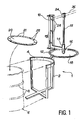
- Figure 1 shows the device object of the invention which consists essentially of a vertical upright 2 on which is fixed a half-hoop 4 whose diameter corresponds to the diameter of the barrel 6, shown in phantom, in which one wishes to pack waste.
- This is a metal barrel of a type commonly used in trade and which has, regularly distributed along its axis, grooves such as 8 projecting outside.
- a vertical support 10 fixed to the upper part of the upright 2, the support 10 being integral with a horizontal arm 12 whose end opposite to the arm 10 comprises a guide tube 14 in which can slide vertically a rod 15.
- the latter can be fixed in the guide tube 14 by means of a fixing means, for example a screw 16.
- a cover 18, identical to those used on drums, has been pierced in its center in order to be able be threaded on the rod 15 and it is retained by a compression disc 17 screwed to the lower part of this last, as shown in Figure 2.
- FIG. 1 also shows the cardboard precover 20 which is used for each compacting cycle of the waste in the barrel 6.
- the diameter of the precover 20 is slightly greater than the inside diameter of the barrel 6, but radial slots such as 22 have been provided on its edges so that it can be inserted into the barrel 6 thanks to the deformation of its edges: in fact, the parts 21 comprised between two radial slots 22 are raised during the descent.
- the rod 15 ends at its upper part by a stirrup 24 into which can be introduced a lever 26 shown schematically in phantom in the figure. Notches 28 formed in the vertical support 10 serve as support points for the lever 26.
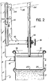
- FIG. 2 The progress of a compaction cycle of the waste is illustrated in the sectional view of FIG. 2.
- the barrel 6 placed inside the half-hoop 4 secured to the upright 2.
- the screw 16a been loosened so that the rod 15 can slide in the guide tube 14.
- the cardboard precover 20 is placed at the top of the waste mass 7 and it is pushed in via the compression disc 17 and the rod 15 on which one acts by means of the lever 26. Au during this movement, the waste settles and the descent of the precover 20 is made possible by the deformation of its edges, the different sectors 21 of which have risen.
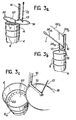
- FIG. 3a we see the barrel 6 placed in the half-hoop 4 and completely filled with a mass of waste 7 not packed.
- the precover 20 is then installed in which radial slots 22 have been made, then the lever 26 is put in place as shown in FIG. 3b.
- the lever is placed in the notch 28a located at the bottom of the support 10 and is in the position 26a shown in solid lines on the face.
- the last cycle in which the waste is placed at the top of the barrel 6, it is in the notch 28b that the end is placed.
- Figure 3c shows the interior of the barrel after the first compaction cycle.
- the precover 20 which is immobilized because its edges, equipped with radial slots 22, are blocked in the groove 8a which is the first groove from the bottom of the barrel.
- the method and the device according to the invention have numerous advantages, the first of which is an increase in the yield of the barrel filling operations thanks to a filling rate three to four times higher than the usual filling rates.
- the number of drums used is reduced, as well as the transport costs, since a single container is sufficient where three or four were needed with the methods of the prior art.
- the contamination is limited because the waste thus stored is not very active and the cardboard precover is sufficient to limit the contamination by the temporary closure that it provides between two compaction cycles.
- the operator does not directly handle the contaminated products and finally, the device is of a very simple construction, therefore inexpensive, and can possibly be modified for the simultaneous filling of several drums.
- the lever 26 can optionally be replaced by an electrical, hydraulic or pneumatic device, allowing the displacement of the rod 15 under the same conditions as those which have been described previously.
- Another improvement of the invention may consist in using a device for recovering contaminated air trapped in the volume between the cover 18 and the precover 20 during the compression operation, to be sent to an outlet filter of protection.
Abstract
La présente invention a pour object un procédé et un dispositif pour le stockage par compactage de déchets contaminés. Les déchets étant placés dans un fût (6), on les comprime en enfonçant dans le fût (6) un précouvercle (20) dont les bords sont rendus déformables afin d'empêcher une remontée du précouvercle (20) par blocage de ses bords sur les parois du fût (6), notamment par engagement dans des gorges (8) ménagées dans ces parois, puis on recommence le cycle jusqu'à remplissage complet du fût. Application au stockage de déchets radioactifs.The object of the present invention is a method and a device for the storage by compaction of contaminated waste. The waste being placed in a barrel (6), it is compressed by pushing into the barrel (6) a precover (20) whose edges are made deformable in order to prevent a rise of the precover (20) by blocking its edges on the walls of the barrel (6), in particular by engaging in grooves (8) formed in these walls, then the cycle is repeated until the barrel is completely filled. Application to the storage of radioactive waste.
Description
La présente invention est relative à un procédé et un dispositif pour le stockage de matériaux souples contaminés. Plus précisément, elle a pour objet un procédé et un dispositif permettant d'augmenter la quantité de produits stockés dans un volume donné.The present invention relates to a method and a device for the storage of contaminated flexible materials. More specifically, it relates to a method and a device for increasing the quantity of products stored in a given volume.
Habituellement, dans les laboratoires ou les milieux hospitaliers, les objets souples contaminés (blouses, combinaisons, surbottes, gants, cotons, chiffons, vinyle, etc.) font l'objet d'un stockage, soit en vue d'un traitement ultérieur de décontamination, soit en vue de leur évacuation dans une zone de stockage de déchets. Ces objets sont généralement déposés par les utilisateurs dans des fûts métalliques pour les soustraire aux conditions extérieures et localiser une contamination éventuelle. Une fois fermés, ces fûts sont transportés vers les lieux de traitement ou de stockage.Usually, in laboratories or hospitals, contaminated flexible objects (gowns, coveralls, overboots, gloves, cottons, rags, vinyl, etc.) are stored, either for further processing. decontamination, either for disposal in a waste storage area. These objects are generally deposited by users in metal drums to protect them from external conditions and locate possible contamination. Once closed, these drums are transported to places of treatment or storage.
Cette façon de faire présente l'inconvénient que les objets ainsi mis au rebut ne peuvent pas être tassés dans les fûts en raison de leur souplesse ou de leur élasticité, et, par conséquent, c'est une masse relativement faible de déchets qui peut être stockée dans un volume donné.This procedure has the disadvantage that the discarded objects cannot be packed in the drums because of their flexibility or elasticity, and therefore it is a relatively small mass of waste that can be stored in a given volume.
La présente invention a justement pour but d'améliorer le rendement de cette opération en permettant de stocker un grand nombre de déchets dans un fût de volume donné.The object of the present invention is precisely to improve the efficiency of this operation by making it possible to store a large number of waste in a barrel of given volume.
Selon la principale caractéristique du procédé objet de l'invention, celui-ci comprend les étapes suivantes :
- - on place les déchets dans un fût,
- - on dispose, au-dessus des déchets, un précouvercle de diamètre légèrement supérieur à celui du fût et dont les bords ont été rendus déformables,
- - on enfonce le précouvercle dans le fût afin de compacter les déchets, le précouvercle étant empêché de remonter grâce au blocage de ses bords sur les parois du fût, et
- - on recommence le cycle en mettant à nouveau des déchets dans le fût, jusqu'à remplissage complet de celui-ci.
- - the waste is placed in a barrel,
- - there is, above the waste, a precover with a diameter slightly greater than that of the barrel and the edges of which have been made deformable,
- - the precover is pressed into the barrel in order to compact the waste, the precover being prevented from rising thanks to the blocking of its edges on the walls of the barrel, and
- - the cycle is started again by putting waste back into the barrel, until it is completely filled.
De préférence, le fût comporte des gorges et le blocage des bords du précouvercle s'effectue dans ces gorges.Preferably, the barrel has grooves and the locking of the edges of the precover takes place in these grooves.
Dans le mode préféré de mise en oeuvre, on utilise comme précouvercle un disque en carton sur les bords duquel on a ménagé des fentes radiales.In the preferred embodiment, a cardboard disc is used as a precover on the edges of which radial slots have been provided.
L'invention a également pour objet un dispositif pour la mise en oeuvre de ce procédé. Selon la principale caractéristique de ce dispositif, celui-ci comporte d'une part des moyens de mise en place du fût et d'autre part des moyens d'application d'une pression sur le précouvercle.The invention also relates to a device for implementing this method. According to the main characteristic of this device, it comprises on the one hand means for positioning the barrel and on the other hand means for applying pressure to the precover.
Dans le mode de réalisation préféré, les moyens de mise en place du fût comprennent un montant vertical sur lequel est monté un arceau semi-circulaire dont le diamètre correspond à celui du fût.In the preferred embodiment, the means for positioning the barrel comprise a vertical upright on which is mounted a semi-circular arch, the diameter of which corresponds to that of the barrel.
Suivant une autre caractéristique de ce dispositif, les moyens permettant d'appliquer une pression sur le précouvercle comprennent :
- - un support vertical,
- - un bras mobile en rotation autour d'un axe vertical solidaire dudit support,
- - une tige coulissante pouvant coulisser à travers un tube-guide monté à une extrémité du bras,
- - un disque de compression monté à une extrémité de la tige coulissante, et
- - un levier permettant d'exercer une force sur l'autre extrémité de la tige coulissante.
- - a vertical support,
- - an arm movable in rotation about a vertical axis integral with said support,
- - a sliding rod which can slide through a guide tube mounted at one end of the arm,
- - a compression disk mounted at one end of the sliding rod, and
- - a lever allowing to exert a force on the other end of the sliding rod.
De préférence ledit montant et ledit support sont confondus ou bien le support est fixé sur le montant.Preferably said amount and said support are combined or the support is fixed to the amount.
L'invention apparaîtra mieux à la lecture de la description qui va suivre d'un exemple de réalisation, description donnée à titre purement illlustratif et nullement limitatif, en référence aux dessins annexés dans lesquels :
- - la figure 1 est une vue schématique en perspective du dispositif objet de l'invention ;
- - la figure 2 est une vue schématique en coupe verticale de ce même dispositif montrant comment les déchets sont tassés à l'intérieur du fût ; et
- - les figures 3a à 3c sont des vues schématiques en perspective illustrant les différentes phases d'un cycle de tassement.
- - Figure 1 is a schematic perspective view of the device object of the invention;
- - Figure 2 is a schematic vertical sectional view of the same device showing how the waste is packed inside the barrel; and
- - Figures 3a to 3c are schematic perspective views illustrating the different phases of a compaction cycle.
La figure 1 montre le dispositif objet de l'invention qui se compose essentiellement d'un montant vertical 2 sur lequel est fixé un demi-arceau 4 dont le diamètre correspond au diamètre du fût 6, représenté en traits mixtes, dans lequel on désire tasser les déchets. Celui-ci est un fût métallique d'un type couramment utilisé dans le commerce et qui présente, régulièrement réparties suivant son axe, des gorges telles que 8 faisant saillie à l'extérieur. On voit encore sur la figure un support vertical 10 fixé à la partie supérieure du montant 2, le support 10 étant solidaire d'un bras horizontal 12 dont l'extrémité opposée au bras 10 comporte un tube-guide 14 dans lequel peut coulisser verticalement une tige 15. Cette dernière peut être fixée dans le tube-guide 14 grâce à un moyen de fixation, par exemple une vis 16. Un couvercle 18, identique à ceux qui sont utilisés sur les fûts, a été percé en son centre afin de pouvoir être enfilé sur la tige 15 et il est retenu par un disque de compression 17 vissé à la partie inférieure de cette dernière, comme cela est illustré à la figure 2.Figure 1 shows the device object of the invention which consists essentially of a vertical upright 2 on which is fixed a half-
La figure 1 montre également le précouvercle en carton 20 qui est utilisé pour chaque cycle de tassement des déchets dans le fût 6. Comme on peut le voir sur la figure, le diamètre du précouvercle 20 est légèrement supérieur au diamètre intérieur du fût 6, mais on a prévu sur ses bords des fentes radiales telles que 22 afin de pouvoir l'enfoncer dans le fût 6 grâce à la déformation de ses bords : en effet, les parties 21 comprises entre deux fentes radiales 22 se relèvent au cours de la descente. Enfin, la tige 15 se termine à sa partie supérieure par un étrier 24 dans lequel peut être introduit un levier 26 représenté schématiquement en traits mixtes sur la figure. Des encoches 28 ménagées dans le support vertical 10 servent de points d'appui au levier 26.FIG. 1 also shows the
Le déroulement d'un cycle de tassement des déchets est illustré sur la vue en coupe de la figure 2. Sur cette figure, on voit le fût 6 placé à l'intérieur du demi-arceau 4 solidaire du montant 2. La vis 16 a été desserrée afin que la tige 15 puisse coulisser dans le tube-guide 14. On commence par introduire les déchets 7 sans les tasser dans le fût 6 jusqu'à remplissage complet de celui-ci. A ce moment, on place le précouvercle 20 en carton à la partie supérieure de la masse de déchets 7 et on l'enfonce par l'intermédiaire du disque de compression 17 et de la tige 15 sur laquelle on agit grâce au levier 26. Au cours de ce mouvement, les déchets se tassent et la descente du précouvercle 20 est rendu possible par la déformation de ses bords, dont les différents secteurs 21 se sont relevés. Lorsque les déchets ont été tassés au maximum, on relâche la pression exercée sur la tige 15 et on relève cette dernière. Les déchets gonflent du fait de leur élasticité, et repoussent le précouvercle 20 vers le haut, mais, lorsque que celui-ci arrive au niveau de l'une des gorges 8, on voit que ses bords ont tendance à reprendre leur position normale et le mouvement de remontée s'arrête car les bords du précouvercle 20 sont bloqués dans la gorge 8. Un blocage suffisant peut être obtenu par le simple frottement des bords du précouvercle sur la paroi latérale du fût ; il peut donc avoir lieu en dehors des gorges sur un fût qui en est muni, ou à un niveau quelconque sur un fût qui serait dépourvu de gorges. A ce moment, on recommence le cycle en mettant des déchets au-dessus du précouvercle 20 et l'on recommence l'opération avec un autre précouvercle jusqu'à remplissage complet du fût. On remarque également sur la figure 2 qu'au cours de chaque cycle de tassement, le fût 6 est fermé par le couvercle 18 troué en son centre puisque celui-ci a été enfilé sur la tige 15 avant que l'on ne visse le disque de compression 17 à la base de celle-ci.The progress of a compaction cycle of the waste is illustrated in the sectional view of FIG. 2. In this figure, we see the
Lorsque le remplissage est terminé, le fût est définitivement fermé avec son couvercle étanche.When the filling is finished, the barrel is definitively closed with its tight lid.
Les figures 3a à 3c résument les différentes étapes du procédé objet de l'invention. Sur la figure 3a, on voit le fût 6 placé dans le demi-arceau 4 et complètement rempli d'une masse de déchets 7 non tassés. On installe ensuite le précouvercle 20 dans lequel ont été ménagées des fentes radiales 22, puis on met en place le levier 26 comme indiqué sur la figure 3b. Lors de la première compression, qui correspond au tassement des déchets dans la partie la plus basse du fût 6, le levier est placé dans l'encoche 28a située à la partie inférieure du support 10 et se trouve dans la position 26a représentée en traits pleins sur la figure. Lors du dernier cycle, dans lequel les déchets sont placés à la partie supérieure du fût 6, c'est dans l'encoche 28b qu'on place l'extrémité de ce levier, qui est alors dans la position 26b représentée schématiquement en traits mixtes. Enfin, la figure 3c montre l'intérieur du fût après le premier cycle de tassement. On voit, à l'intérieur du fût 6, le précouvercle 20 qui est immobilisé car ses bords, équipés des fentes radiales 22, sont bloqués dans la gorge 8a qui est la première gorge à partir de la partie basse du fût.Figures 3a to 3c summarize the different steps of the process which is the subject of the invention. In Figure 3a, we see the
Le procédé et le dispositif selon l'invention présentent de nombreux avantages dont le premier est une augmentation du rendement des opérations de remplissage des fûts grâce à un taux de remplissage supérieur de trois à quatre fois aux taux de remplissage habituels. D'autre part, on diminue le nombre de fûts utilisés, ainsi que les frais de transport, puisqu'un seul récipient suffit là où il en fallait trois ou quatre avec les méthodes de l'art antérieur. D'autre part, la contamination est limitée car les déchets ainsi stockés ne sont pas très actifs et le précouvercle en carton suffit à limiter la contamination par la fermeture provisoire qu'il procure entre deux cycles de tassement. De plus, l'opérateur ne manipule pas directement les produits contaminés et enfin, le dispositif est d'une construction très simple, donc peu coûteuse, et peut éventuellement être modifié pour le remplissage simultané de plusieurs fûts.The method and the device according to the invention have numerous advantages, the first of which is an increase in the yield of the barrel filling operations thanks to a filling rate three to four times higher than the usual filling rates. On the other hand, the number of drums used is reduced, as well as the transport costs, since a single container is sufficient where three or four were needed with the methods of the prior art. On the other hand, the contamination is limited because the waste thus stored is not very active and the cardboard precover is sufficient to limit the contamination by the temporary closure that it provides between two compaction cycles. In addition, the operator does not directly handle the contaminated products and finally, the device is of a very simple construction, therefore inexpensive, and can possibly be modified for the simultaneous filling of several drums.
Bien entendu, l'invention ne se limite pas au seul mode de réalisation qui vient d'être décrit et on peut envisager des variantes sans sortir pour autant du cadre de l'invention.Of course, the invention is not limited to the single embodiment which has just been described and it is possible to envisage variants without thereby departing from the scope of the invention.
Par exemple, on peut adapter la forme et les dimensions des différents éléments du dispositif en fonction des fûts utilisés ou choisir un autre matériau que le carton pour le précouvercle 20, l'essentiel étant qu'on puisse rendre ses bords déformables afin de permettre son enfoncement dans le fût et son blocage sur les parois ou dans les gorges de celui-ci.For example, we can adapt the shape and dimensions of the different elements of the device according to the drums used or choose a material other than cardboard for the
On peut également placer à l'intérieur du fût un sac en matière plastique suffisamment résistant, éliminer le disque de compression en utilisant un précouvercle plus rigide, et adopter pour l'appareil une configuration non verticale, horizontale ou oblique.You can also place a sufficiently resistant plastic bag inside the barrel, eliminate the compression disk using a more rigid precover, and adopt a non-vertical, horizontal or oblique configuration for the device.
Le levier 26 peut être éventuellement remplacé par un dispositif électrique, hydraulique ou pneumatique, permettant le déplacement de la tige 15 dans les mêmes conditions que celles qui ont été décrites précédemment.The
Une autre amélioration de l'invention peut consister à utiliser un dispositif de récupération de l'air contaminé emprisonné dans le volume compris entre le couvercle 18 et le précouvercle 20 lors de l'opération de compression, pour être envoyé sur un filtre de sortie de protection.Another improvement of the invention may consist in using a device for recovering contaminated air trapped in the volume between the
Claims (8)
Applications Claiming Priority (2)
| Application Number | Priority Date | Filing Date | Title |
|---|---|---|---|
| FR8216285A FR2533743A1 (en) | 1982-09-28 | 1982-09-28 | METHOD AND DEVICE FOR STORAGE BY COMPACTION OF CONTAMINATED FLEXIBLE MATERIALS |
| FR8216285 | 1982-09-28 |
Publications (2)
| Publication Number | Publication Date |
|---|---|
| EP0105002A1 true EP0105002A1 (en) | 1984-04-04 |
| EP0105002B1 EP0105002B1 (en) | 1987-04-01 |
Family
ID=9277799
Family Applications (1)
| Application Number | Title | Priority Date | Filing Date |
|---|---|---|---|
| EP83401873A Expired EP0105002B1 (en) | 1982-09-28 | 1983-09-26 | Process and device for storing pliable contaminated materials by compacting |
Country Status (4)
| Country | Link |
|---|---|
| US (1) | US4564469A (en) |
| EP (1) | EP0105002B1 (en) |
| DE (1) | DE3370716D1 (en) |
| FR (1) | FR2533743A1 (en) |
Cited By (4)
| Publication number | Priority date | Publication date | Assignee | Title |
|---|---|---|---|---|
| FR2584854A1 (en) * | 1985-07-09 | 1987-01-16 | Commissariat Energie Atomique | Process and plant for compacting and packaging solid radioactive waste of low or intermediate activity |
| US4980094A (en) * | 1988-02-26 | 1990-12-25 | British Nuclear Fuel Plc | Methods and apparatus for closing and charging radioactive waste containers |
| EP1124234A1 (en) * | 2000-02-11 | 2001-08-16 | Jesse Yang | Method for sealing and packing toxic wastes |
| AT522299A2 (en) * | 2019-04-12 | 2020-10-15 | Spiwak Michael | Collection system for waste, in particular paper waste |
Families Citing this family (14)
| Publication number | Priority date | Publication date | Assignee | Title |
|---|---|---|---|---|
| US4748908A (en) * | 1986-01-07 | 1988-06-07 | Fab Masters, Inc. | Waste containers having compressed waste hold-down mechanisms |
| US4669506A (en) * | 1986-02-05 | 1987-06-02 | Nuclear Energy Systems, Inc. | Resilient domed partition |
| US4777874A (en) * | 1986-05-16 | 1988-10-18 | Phelps Engineering Company, Inc. | Anti-springback device for a container |
| US5388391A (en) * | 1988-12-19 | 1995-02-14 | Parker; Richard D. | Apparatus and process for packaging biohazardous wastes |
| DE3925866A1 (en) * | 1989-08-04 | 1991-02-07 | Friedhelm Schneider | DEVICE FOR EMPTYING BARRELS WITH HIGH VISCOSITY CONTENT |
| EP0499335A3 (en) * | 1991-02-14 | 1993-03-10 | Russell Stanley Corporation | Drum and process for handling drum liners |
| US5361692A (en) * | 1992-10-13 | 1994-11-08 | John Zimmer | Compaction system for metal drums |
| SE503118C2 (en) * | 1993-11-25 | 1996-03-25 | Asea Atom Ab | Method and apparatus for stirring a mixture in a container |
| US5471065A (en) * | 1994-01-27 | 1995-11-28 | Harrell; James L. | Macroencapsulation of hazardous waste |
| US5704404A (en) * | 1995-07-25 | 1998-01-06 | Balding, Jr.; William E. | Method and device for compacting resilient waste materials for storage and disposal |
| FR2759058A1 (en) * | 1997-02-06 | 1998-08-07 | Cml Invest | Procedure for packing materials, e.g. toxic industrial waste, by compacting |
| DE102012219076B4 (en) * | 2012-10-19 | 2014-05-15 | Areva Gmbh | Hold-down device for nuclear reactor residuals and nuclear residual disposal method |
| US10329035B2 (en) * | 2017-10-03 | 2019-06-25 | Hamilton Sundstrand Corporation | Fecal collection bag retention device for use in zero gravity |
| CN108115966A (en) * | 2017-12-12 | 2018-06-05 | 纪美 | A kind of efficient clothing compression set |
Citations (3)
| Publication number | Priority date | Publication date | Assignee | Title |
|---|---|---|---|---|
| GB1131629A (en) * | 1965-04-05 | 1968-10-23 | Mayer & Co Inc O | Package and method of forming same |
| DE2214871A1 (en) * | 1972-03-27 | 1973-10-11 | Hans Ungemach | PROCEDURE FOR FILLING BAG-LIKE, ELASTIC CONTAINERS WITH GOODS OF ALL KINDS |
| EP0044381A1 (en) * | 1980-05-19 | 1982-01-27 | Asea Ab | Method for treating radioactive material and container for enclosing such material |
Family Cites Families (7)
| Publication number | Priority date | Publication date | Assignee | Title |
|---|---|---|---|---|
| US532750A (en) * | 1895-01-22 | Cotton-press | ||
| US1002559A (en) * | 1909-10-19 | 1911-09-05 | Richard Albert Canfield | Machine for applying stoppers or sealing devices. |
| US1242232A (en) * | 1916-06-16 | 1917-10-09 | William J Palm | Waste-paper press. |
| US3157086A (en) * | 1962-01-18 | 1964-11-17 | Theodore J Bachhuber | Shotgun shell reloader |
| US3757682A (en) * | 1971-07-14 | 1973-09-11 | Automatic Refuse System Inc | Dolly-mounted bag holder for refuse compactor |
| DE2813210C2 (en) * | 1978-03-25 | 1980-05-14 | Thiele U. Co, 2800 Bremen | Container fastening device |
| US4462310A (en) * | 1982-12-21 | 1984-07-31 | Jackson O L | Compacting device |
-
1982
- 1982-09-28 FR FR8216285A patent/FR2533743A1/en active Granted
-
1983
- 1983-09-26 EP EP83401873A patent/EP0105002B1/en not_active Expired
- 1983-09-26 DE DE8383401873T patent/DE3370716D1/en not_active Expired
- 1983-09-28 US US06/536,505 patent/US4564469A/en not_active Expired - Fee Related
Patent Citations (3)
| Publication number | Priority date | Publication date | Assignee | Title |
|---|---|---|---|---|
| GB1131629A (en) * | 1965-04-05 | 1968-10-23 | Mayer & Co Inc O | Package and method of forming same |
| DE2214871A1 (en) * | 1972-03-27 | 1973-10-11 | Hans Ungemach | PROCEDURE FOR FILLING BAG-LIKE, ELASTIC CONTAINERS WITH GOODS OF ALL KINDS |
| EP0044381A1 (en) * | 1980-05-19 | 1982-01-27 | Asea Ab | Method for treating radioactive material and container for enclosing such material |
Cited By (5)
| Publication number | Priority date | Publication date | Assignee | Title |
|---|---|---|---|---|
| FR2584854A1 (en) * | 1985-07-09 | 1987-01-16 | Commissariat Energie Atomique | Process and plant for compacting and packaging solid radioactive waste of low or intermediate activity |
| US4980094A (en) * | 1988-02-26 | 1990-12-25 | British Nuclear Fuel Plc | Methods and apparatus for closing and charging radioactive waste containers |
| EP1124234A1 (en) * | 2000-02-11 | 2001-08-16 | Jesse Yang | Method for sealing and packing toxic wastes |
| AT522299A2 (en) * | 2019-04-12 | 2020-10-15 | Spiwak Michael | Collection system for waste, in particular paper waste |
| AT522299A3 (en) * | 2019-04-12 | 2020-11-15 | Spiwak Michael | Collection system for waste, in particular paper waste |
Also Published As
| Publication number | Publication date |
|---|---|
| EP0105002B1 (en) | 1987-04-01 |
| DE3370716D1 (en) | 1987-05-07 |
| US4564469A (en) | 1986-01-14 |
| FR2533743A1 (en) | 1984-03-30 |
| FR2533743B1 (en) | 1984-12-21 |
Similar Documents
| Publication | Publication Date | Title |
|---|---|---|
| EP0105002B1 (en) | Process and device for storing pliable contaminated materials by compacting | |
| EP0472457B1 (en) | Purging and flushing apparatus for disposable bottles containing a toxic product | |
| EP3903923B1 (en) | Method for complete draining of a catalytic reactor by means of an articulated arm provided with rotary spiral protrusions | |
| CA1202460A (en) | Device with vertical floating mandrel assembly for positioning and centering a thermoplastique sheath around objects | |
| EP0078212A1 (en) | Apparatus for sampling liquids | |
| FR2783345A1 (en) | Hazardous waste-containing drum filling process, e.g. for mortar or grout filling of drum containing low level radioactive waste 'cakes', comprises pressure reduction of the drum and a confinement bell during drum perforation and injection | |
| EP0774761B1 (en) | Container for packaging and storing, especially suited for remotely handled hazardous waste material; filling method thereof and carrying of the method for the packaging and storing of compacted nuclear wastes | |
| BE1003757A3 (en) | Method for producing brushes with respect freedom and not tied in beam and a brush making machine for making this process. | |
| FR2631924A1 (en) | Automatic method for installing a stretchable sleeve tube for labelling plastic or metal packages and device for implementing this method | |
| FR2549020A1 (en) | TRANSPORTATION SYSTEM FOR FLAT OBJECTS TRANSPORTED BY AN AIRFLOW | |
| EP0115978B1 (en) | Machine for closing barrels inside a pool, and cover for a barrel used by this machine | |
| EP0337146B1 (en) | Dispenser for pills, tablets or the like | |
| FR2660217A1 (en) | METHOD FOR STORING FUTS IN DRILLING HOLES AND DEVICE FOR ITS IMPLEMENTATION | |
| EP0322269A1 (en) | Automatic sachet dispenser | |
| FR2574563A1 (en) | METHOD FOR LOADING OPTICAL FIBERS AND DEVICE FOR CARRYING OUT SAID METHOD | |
| EP0475830B1 (en) | Method and plug for the permanent closure of a storage well | |
| CA1247066A (en) | Funneled bagging machine | |
| FR2584854A1 (en) | Process and plant for compacting and packaging solid radioactive waste of low or intermediate activity | |
| FR2553388A3 (en) | Coconuts emptied of their water, then filled with alcohol, stoppered and sealed, thus serving as a container. They are then decorated and personalised | |
| EP0731025A1 (en) | Canning of elongated products such as green beans | |
| EP0762039A1 (en) | Method of connecting a branch pipe to a main | |
| FR2516852A1 (en) | MOLDING DEVICE FOR CONCRETE ELEMENTS, SUCH AS PIPES, WELL ELEMENTS OR THE LIKE | |
| CH327554A (en) | Device for presenting and loading suppositories in bulk for their placement in blister packs | |
| BE558385A (en) | ||
| WO1987000505A1 (en) | Machine for inserting fruit in preserve jars |
Legal Events
| Date | Code | Title | Description |
|---|---|---|---|
| PUAI | Public reference made under article 153(3) epc to a published international application that has entered the european phase |
Free format text: ORIGINAL CODE: 0009012 |
|
| AK | Designated contracting states |
Designated state(s): BE CH DE GB IT LI NL |
|
| 17P | Request for examination filed |
Effective date: 19840908 |
|
| 17Q | First examination report despatched |
Effective date: 19860121 |
|
| GRAA | (expected) grant |
Free format text: ORIGINAL CODE: 0009210 |
|
| AK | Designated contracting states |
Kind code of ref document: B1 Designated state(s): BE CH DE GB IT LI NL |
|
| REF | Corresponds to: |
Ref document number: 3370716 Country of ref document: DE Date of ref document: 19870507 |
|
| ITF | It: translation for a ep patent filed |
Owner name: JACOBACCI & PERANI S.P.A. |
|
| BECN | Be: change of holder's name |
Effective date: 19870401 |
|
| RAP2 | Party data changed (patent owner data changed or rights of a patent transferred) |
Owner name: COMMISSARIAT A L'ENERGIE ATOMIQUE |
|
| PLBE | No opposition filed within time limit |
Free format text: ORIGINAL CODE: 0009261 |
|
| STAA | Information on the status of an ep patent application or granted ep patent |
Free format text: STATUS: NO OPPOSITION FILED WITHIN TIME LIMIT |
|
| NLT2 | Nl: modifications (of names), taken from the european patent patent bulletin |
Owner name: COMMISSARIAT A L'ENERGIE ATOMIQUE TE PARIJS, FRANK |
|
| 26N | No opposition filed | ||
| PGFP | Annual fee paid to national office [announced via postgrant information from national office to epo] |
Ref country code: BE Payment date: 19900822 Year of fee payment: 8 |
|
| PGFP | Annual fee paid to national office [announced via postgrant information from national office to epo] |
Ref country code: DE Payment date: 19900824 Year of fee payment: 8 |
|
| PGFP | Annual fee paid to national office [announced via postgrant information from national office to epo] |
Ref country code: GB Payment date: 19900907 Year of fee payment: 8 |
|
| PGFP | Annual fee paid to national office [announced via postgrant information from national office to epo] |
Ref country code: CH Payment date: 19900924 Year of fee payment: 8 |
|
| ITTA | It: last paid annual fee | ||
| PGFP | Annual fee paid to national office [announced via postgrant information from national office to epo] |
Ref country code: NL Payment date: 19900930 Year of fee payment: 8 |
|
| PG25 | Lapsed in a contracting state [announced via postgrant information from national office to epo] |
Ref country code: GB Effective date: 19910926 |
|
| PG25 | Lapsed in a contracting state [announced via postgrant information from national office to epo] |
Ref country code: LI Effective date: 19910930 Ref country code: CH Effective date: 19910930 Ref country code: BE Effective date: 19910930 |
|
| BERE | Be: lapsed |
Owner name: COMMISSARIAT A L'ENERGIE ATOMIQUE Effective date: 19910930 |
|
| PG25 | Lapsed in a contracting state [announced via postgrant information from national office to epo] |
Ref country code: NL Effective date: 19920401 |
|
| NLV4 | Nl: lapsed or anulled due to non-payment of the annual fee | ||
| GBPC | Gb: european patent ceased through non-payment of renewal fee | ||
| REG | Reference to a national code |
Ref country code: CH Ref legal event code: PL |
|
| PG25 | Lapsed in a contracting state [announced via postgrant information from national office to epo] |
Ref country code: DE Effective date: 19920602 |