EP0104600A2 - Zentrifugenrotor mit verschliessbarem Windschirm - Google Patents
Zentrifugenrotor mit verschliessbarem Windschirm Download PDFInfo
- Publication number
- EP0104600A2 EP0104600A2 EP83109379A EP83109379A EP0104600A2 EP 0104600 A2 EP0104600 A2 EP 0104600A2 EP 83109379 A EP83109379 A EP 83109379A EP 83109379 A EP83109379 A EP 83109379A EP 0104600 A2 EP0104600 A2 EP 0104600A2
- Authority
- EP
- European Patent Office
- Prior art keywords
- rotor
- windshield
- shaft
- lower portion
- buckets
- Prior art date
- Legal status (The legal status is an assumption and is not a legal conclusion. Google has not performed a legal analysis and makes no representation as to the accuracy of the status listed.)
- Granted
Links
Images


Classifications
-
- B—PERFORMING OPERATIONS; TRANSPORTING
- B04—CENTRIFUGAL APPARATUS OR MACHINES FOR CARRYING-OUT PHYSICAL OR CHEMICAL PROCESSES
- B04B—CENTRIFUGES
- B04B5/00—Other centrifuges
- B04B5/04—Radial chamber apparatus for separating predominantly liquid mixtures, e.g. butyrometers
- B04B5/0407—Radial chamber apparatus for separating predominantly liquid mixtures, e.g. butyrometers for liquids contained in receptacles
- B04B5/0414—Radial chamber apparatus for separating predominantly liquid mixtures, e.g. butyrometers for liquids contained in receptacles comprising test tubes
- B04B5/0421—Radial chamber apparatus for separating predominantly liquid mixtures, e.g. butyrometers for liquids contained in receptacles comprising test tubes pivotably mounted
-
- B—PERFORMING OPERATIONS; TRANSPORTING
- B04—CENTRIFUGAL APPARATUS OR MACHINES FOR CARRYING-OUT PHYSICAL OR CHEMICAL PROCESSES
- B04B—CENTRIFUGES
- B04B7/00—Elements of centrifuges
- B04B7/02—Casings; Lids
-
- B—PERFORMING OPERATIONS; TRANSPORTING
- B04—CENTRIFUGAL APPARATUS OR MACHINES FOR CARRYING-OUT PHYSICAL OR CHEMICAL PROCESSES
- B04B—CENTRIFUGES
- B04B7/00—Elements of centrifuges
- B04B7/02—Casings; Lids
- B04B2007/025—Lids for laboratory centrifuge rotors
Definitions
- This invention relates to a centrifuge rotor, and in particular, to a swinging bucket centrifuge rotor having a windshield a portion which is movable with respect to the rotor shaft from a rest to a closed position.
- the relative centrifugal force developed by a rotor is windage limited. That is, for a given rotor volume the maximum operating speed at which that rotor may rotate is usually limited by the drive torque available to the rotor at that speed. Thus increasing rotor volume, as by increasing the number or size of the buckets, may have an adverse effect upon the amount of relative centrifugal force able to be generated by the rotor.
- windshielding a swinging bucket rotors minimizes pumping losses and thereby contributes to increased relative centrifugal force it is not possible to merely increase the volume of the buckets within the windshielded rotor and thereby increase rotor volume while maintaining the same relative centrifugal force. This is because the configuration of the windshield itself imposes windage losses on the system which are increased as the windshield increases in size.
- the present invention deals with a centrifuge apparatus wherein the windage generated by a swinging bucket rotor of a given volume may be decreased thereby increasing the relative centrifugal force able to be generated by a rotor at that volume.
- the rotor comprises a shaft having a plurality of buckets pivotally mounted thereto, the buckets being movable from a rest position in which the axis of each bucket lies parallel to the axis of rotation to an operating position in which the axis of each of the buckets extends in a plane substantially perpendicular to the rotor's axis of rotation.
- An upper windshield portion is attached to the shaft, the outer boundary of the upper windshield portion terminating in a mating edge.
- a lower windshield portion also having a mating edge thereon is movably mounted with respect to the shaft in a direction parallel to the axis of rotation.
- the lower windshield portion is movable with respect to the shaft from an open position in which the lower windshield portion lies on the shaft at a position below the buckets as they occupy their rest position to a closed position in which the mating edges on the lower and upper windshield portions are engaged.
- the lower windshield portion moves with respect to the shaft to the closed position in response to a closing force generated as a result of the rotation of the rotor.
- the closing force is the result of the pressure differential generated by the centrifugal pumping action of the rotor and buckets.
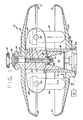
- a centrifuge rotor of the swinging bucket type generally indicated by reference numeral 10 includes a central hub 12 having a lower skirt portion 14 thereon.
- a central axial bore 16 having a truncated conical portion 18 extends through the interior of the rotor 10.
- a drive adapter 20 having an enlargement 22 thereon extends through the bore 16.
- the upper end of the drive adapter 20 is provided with threads 24 which receive a cover drive nut 26.
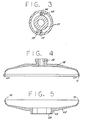
- the enlargement 22 of the adapter 20 is provided with an annular groove 30 in which drive posts 34 (only one of which is visible in Figure 1) are disposed (see also Figure 3).
- a rotor gyro 36 having drive pins 38 thereon extends into the conical portion 18 of the bore with the pins 38 extending into the groove 30.
- the adapter 20 is itself provided with a central axial bore 40.
- a knob 41 having an elongated threaded rod 42 connected thereto extends through the bore 40 to secure the rotor 10 to the gyro 36.
- the knob 41 clamps a cover 54 to the hub portion 12 of the rotor 10 to prevent relative motion between the center of gravity of the rotor 10 and the cover 54.
- the gyro 36 is operatively connected to a drive motor 44 as shown by the schematic linkage 46. Rotation of the gyro 36 brings the pins 38 thereon into driving engagement with the pins 34 (believed best seen in Figure 3) to thereby rotate the rotor 10.
- the rotor 10 includes a plurality of arms 48 extending radially outwardly from the central hub 12 of the shaft.
- a plurality of swinging buckets 52 is pivotally mounted by any suitable means of attachment (such as trunnion pins 50) between pairs of adjacent ones of the arms 48.
- the buckets 52 are pivotable from a rest position ( Figure 1) in which the axis A of each of the buckets 52 is substantially parallel to the rotor's axis of rotation S to an operating position in which the axes A of the buckets 52 lie generally perpendicular to the axis S.
- a rest position Figure 1
- the axis A of each of the buckets 52 is substantially parallel to the rotor's axis of rotation S
- an operating position in which the axes A of the buckets 52 lie generally perpendicular to the axis S.
- the axis of each bucket may assume any predetermined orientation with respect to the axis S.
- An upper windshield portion 54 ( Figures 1 and 4) is removably mounted to the drive cover nut 26.
- the upper windshield portion 54 is provided with a hexagonal opening 56 ( Figure 4) which is received on the drive nut 26 so as to prevent rotation of upper windshield 54 with respect to the hub 12.
- the outer peripheral edge of the upper windshield portion 54 terminates in a mating surface 60.
- a lower windshield portion 62 ( Figures 1 and 5) has a central region 64 through which an opening 66 extends.
- the lower windshield portion 62 is movably mounted on the skirt portion 14 of the shaft between an open position (Figure 1) defined by a lower stop 68 mounted to the shaft and a closed position ( Figure 2).
- the outer periphery of the lower windshield portion 62 terminates in a mating surface 70.
- the upper windshield portion 54 is provided with a circumferential annular band 71 the inside diameter of which is greater than the outside diameter of the lower windshield portion 62.
- the upper windshield portion 54 is stiffer than the lower windshield portion 62.
- the lower windshield portion 62 is movable along the skirt 14 in a direction parallel to the axis S between the open and closed positions.
- the lower windshield portion 62 is nonrotatably mounted with respect to the skirt 14.
- the skirt 14 is substantially hexagonal in cross section.
- the opening 66 in the lower windshield portion 62 is correspondingly shaped ( Figure 5).
- the lower windshield portion 62 is thus slidably but nonrotatably mounted to the skirt 14.
- the upper and lower windshield portions may be made nonrotatably mounted to the shaft by any suitable expedient.
- the windshield portions 54 and 62 are fabricated of any suitable material, preferably a high strength aluminum alloy.
- the skirt 14 and boundary surface of the opening 66 in the lower windshield 62 are provided with smooth, highly polished finishes to expedite the sliding movement of the lower windshield with respect thereto.
- the surface of the skirt 14 and the boundary of the opening 66 are provided with an anodized aluminum hardcoat.
- any suitable solid film lubrication may be utilized whatever construction materials are used to fabricate the rotor and windshield portions.
- the buckets 52 respond to the motive energy applied to the rotor by pivoting from the rest position ( Figure 1) to the operating position ( Figure 2) in which the axes A of the buckets 52 extend substantially perpendicular to the axis S of rotation of the rotor.
- the rotation of the rotor results in the generation of a closing force acting in the directon of the arrow 72 which moves the lower portion 52 of the windshield to the closed position.
- the closing force is generated by a pressure differential defined in the region between the portions of the windshield.
- air in the vicinity of the rotating buckets is pumped radially outwardly relative to the axis S of the rotor to thereby define a lower pressure region substantially between the upper and lower windshield portions.
- the lower portion 62 of the windshield responds to the pressure force generated by the pressure differential formed between the exterior of the lower portion and the interior thereof by the centrifuged pumping action of the rotor arms and the buckets 52 to displace the lower portion 62 along the skirt 14 in the direction of the arrow 72 (parallel to the axis S) from the open position to the closed position.
- the lower windshield portion 62 is sized and weighted to insure that the closing motion does not occur prior to the time that the buckets 52 assume their operating orientation.
- the lower portion 62 of the windshield will drop to the open position at a rotational speed which is greater than the speed at which the buckets 52 drop toward the rest position.
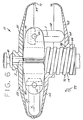
- FIG. 6 shown are alternate embodiments of the invention.
- that part of the Figure shown to the right of the axis S of the rotor depicts the lower windshield portion 62 in the lower position while the part of the Figure to the left of the axis S shows the lower windshield portion 62 in the closed position.
- the exterior surface of the shaft 14 is provided with a jack screw thread, as at 76.
- the opening 66 in the central region 64 of the lower portion 62 is correspondingly threaded as at 78 to form a nut fitting to the jack screw.
- the lower , windshield portion 62 is provided with a plurality of airfoils 82 along the periphery thereof.
- the exact number, length, aspect ratio and angle of attack we selected so as to produce the least drag at the maximum rotor speed while still producing the closing force in the form of sufficient lift to move the lower portion 62 of the windshield to the closed position.
- Figure 8 discloses an alternate embodiment of the invention which a fluid piston is used to generate the closing force to close the lower portion 62 of the windshield.
- a cylindrical skirt 86 is attached to the central region 64 of the lower portion 62 of the windshield.
- the skirt 14 on the hub 12 is spaced from the interior surface of the region 64 on the lower portion 62 of the windshield and is cooperable with the same and with the skirt 86 to define an annular cylinder 88 therebetween.
- the annular cylinder 88 communicates with a vent volume 90 (shown in the form of a passage) defined within the rotor hub 12.
- the cylinder 88 is sealed by O-rings 92 and 94.
- a fixed volume of hydraulic fluid is disposed within the annular cylinder 88 (and perhaps into the volume 90).
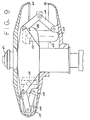
- FIG. 9 A further embodiment of the invention is shown in Figure 9.
- linkages 106 with midweights 108 are mounted intermediate bucket positions.
- the linkages 106 are mounted between pivot pins 110 and 112 respectively disposed on the rotor and the lower portion 62 of the windshield. Centrifugal force acts on the weights 108 to urge them radially outwardly. A resulting closing force acts to lift the lower portion 62 to the closed position.
- the Figure discloses the linkages 106 as extending between the rotor hub 12 and the lower portion 62 of the windshield, any other suitable interconnection may be used. Since this embodiment does not depend upon aerodynamic or pressure differential effects, it is believed best suited in reduced atmosphere environments.
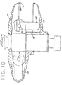
- Fig. 10 shows an embodiment of the invention basically similar to that shown in Figs. 1 through 5.
- Guidewires 114 are securely attached in any convenient manner between the rotor 10 and lower portion 62. As the rotor rotates, the guidewires spiral generally tangentially to the direction of angular rotation, thus shortening the guidewires 114 to thereby assist the movement of the lower portion 62 of the windshield to the closed position.
- centrifuge rotor of the winging bucket type which permits the maximum relative centrifugal force able to be generated by a rotor at a given rotor volume.
Landscapes
- Centrifugal Separators (AREA)
Applications Claiming Priority (2)
| Application Number | Priority Date | Filing Date | Title |
|---|---|---|---|
| US06/427,907 US4435169A (en) | 1982-09-29 | 1982-09-29 | Centrifuge rotor having a closable windshield |
| US427907 | 1982-09-29 |
Publications (3)
| Publication Number | Publication Date |
|---|---|
| EP0104600A2 true EP0104600A2 (de) | 1984-04-04 |
| EP0104600A3 EP0104600A3 (en) | 1986-03-19 |
| EP0104600B1 EP0104600B1 (de) | 1988-03-16 |
Family
ID=23696805
Family Applications (1)
| Application Number | Title | Priority Date | Filing Date |
|---|---|---|---|
| EP83109379A Expired EP0104600B1 (de) | 1982-09-29 | 1983-09-21 | Zentrifugenrotor mit verschliessbarem Windschirm |
Country Status (4)
| Country | Link |
|---|---|
| US (1) | US4435169A (de) |
| EP (1) | EP0104600B1 (de) |
| JP (1) | JPS5980347A (de) |
| DE (1) | DE3375980D1 (de) |
Families Citing this family (30)
| Publication number | Priority date | Publication date | Assignee | Title |
|---|---|---|---|---|
| US4624655A (en) * | 1984-12-21 | 1986-11-25 | E. I. Du Pont De Nemours And Company | Restoring cap assembly for a centrifuge rotor having a flexible carrier |
| US4890947A (en) * | 1988-10-26 | 1990-01-02 | E. I. Du Pont De Nemours And Company | Mounting adapter having locking taper removal arrangement |
| EP0611328A1 (de) * | 1991-10-21 | 1994-08-24 | Beckman Instruments, Inc. | Hybride probenbehälter für zentrifuge |
| US5344380A (en) * | 1992-09-30 | 1994-09-06 | Beckman Instruments, Inc. | Release handle for centrifuge rotor and lid |
| WO1995034382A1 (en) * | 1994-06-15 | 1995-12-21 | Massachusetts Institute Of Technology | Locking centrifuge rotor cover assembly |
| US5415616A (en) * | 1994-07-07 | 1995-05-16 | Beckman Instruments, Inc. | Rotor-protected evacuation port for centrifugal separation |
| US5591114A (en) * | 1995-12-15 | 1997-01-07 | Sorvall Products, L.P. | Swinging bucket centrifuge rotor |
| US5624370A (en) * | 1995-12-15 | 1997-04-29 | Sorvall Products, L.P. | Bucket for use in a swinging bucket centrifuge rotor |
| JP3314603B2 (ja) * | 1996-01-31 | 2002-08-12 | 株式会社日立製作所 | 遠心力載荷試験装置 |
| FR2770154B1 (fr) * | 1997-10-23 | 1999-11-26 | Jouan | Centrifugeuse a rotor demontable et a dispositif de blocage axial du rotor sur une tete d'entrainement, et rotor pour une telle centrifugeuse |
| US5897482A (en) * | 1998-03-04 | 1999-04-27 | Beckman Instruments, Inc. | Rotor lid tie-down and vacuum venting system |
| JP3840888B2 (ja) * | 2000-09-18 | 2006-11-01 | 日立工機株式会社 | 遠心分離機及びそのロータ |
| US6665924B2 (en) * | 2002-01-25 | 2003-12-23 | Kendro Laboratory Products, L.P. | Centrifuge having a spring-loaded nut for securing a rotor to a drive cone |
| US7081081B2 (en) * | 2002-04-22 | 2006-07-25 | Kendro Laboratory Products, Lp | Bayonet coupling mechanism for a centrifuge |
| US6776751B2 (en) * | 2002-04-22 | 2004-08-17 | Kendor Laboratory Products, Lp | Rotor cover attachment apparatus |
| US6764438B2 (en) * | 2002-04-22 | 2004-07-20 | Kendro Laboratory Products, Lp | Cover attachment apparatus |
| US6802803B2 (en) * | 2002-04-22 | 2004-10-12 | Kendro Laboratory Products, Inc. | Cover attachment apparatus |
| US6811531B2 (en) * | 2002-04-22 | 2004-11-02 | Kenneth J. Moscone, Sr. | Horizontal centrifuge rotor |
| US20040071569A1 (en) * | 2002-08-02 | 2004-04-15 | Ellsworth James R. | Decanting centrifuge with vibration isolation |
| US7011618B2 (en) | 2003-05-16 | 2006-03-14 | Kendro Laboratory Products Lp | Attachment and release apparatus for a centrifuge rotor cover |
| DE102004012025C5 (de) * | 2004-03-10 | 2012-04-05 | Eppendorf Ag | Laborzentrifuge mit Ausschwingbehältern |
| US7407296B2 (en) * | 2005-06-10 | 2008-08-05 | Infocus Corporation | Integrated light gathering reflector and optical element holder |
| US7422554B2 (en) * | 2005-08-10 | 2008-09-09 | The Drucker Company, Inc. | Centrifuge with aerodynamic rotor and bucket design |
| JP4941877B2 (ja) * | 2005-10-18 | 2012-05-30 | 日立工機株式会社 | 遠心分離機用ロータ及び遠心分離機 |
| US7837607B2 (en) * | 2006-12-13 | 2010-11-23 | Thermo Fisher Scientific Inc. | Centrifuge rotor assembly and method of connection thereof |
| DE202010014803U1 (de) * | 2010-11-01 | 2010-12-30 | Sigma Laborzentrifugen Gmbh | Rotorlagerung für eine Laborzentrifuge |
| DE102014112501B4 (de) * | 2014-08-29 | 2017-07-27 | Andreas Hettich Gmbh & Co. Kg | Zentrifuge |
| DE102015113855A1 (de) * | 2015-08-20 | 2017-02-23 | Andreas Hettich Gmbh & Co. Kg | Rotor einer Zentrifuge |
| DE102015113854A1 (de) * | 2015-08-20 | 2017-02-23 | Andreas Hettich Gmbh & Co. Kg | Rotor einer Zentrifuge |
| DE102017130787A1 (de) * | 2017-12-20 | 2019-06-27 | Eppendorf Ag | Zentrifugenrotor |
Citations (4)
| Publication number | Priority date | Publication date | Assignee | Title |
|---|---|---|---|---|
| DE557084C (de) * | 1932-08-18 | Hans Jacques Fuchs Dr | In einem Schutzgehaeuse sitzende Becherschleuder | |
| DE2041482A1 (de) * | 1969-08-22 | 1971-03-18 | Aga Ab | Zentrifuge |
| US4010890A (en) * | 1976-01-28 | 1977-03-08 | Beckman Instruments, Inc. | Centrifuge rotor lid |
| JPS5239865A (en) * | 1975-09-23 | 1977-03-28 | Hitachi Koki Co Ltd | Centrifuge |
-
1982
- 1982-09-29 US US06/427,907 patent/US4435169A/en not_active Expired - Lifetime
-
1983
- 1983-09-21 DE DE8383109379T patent/DE3375980D1/de not_active Expired
- 1983-09-21 EP EP83109379A patent/EP0104600B1/de not_active Expired
- 1983-09-28 JP JP58178349A patent/JPS5980347A/ja active Granted
Patent Citations (4)
| Publication number | Priority date | Publication date | Assignee | Title |
|---|---|---|---|---|
| DE557084C (de) * | 1932-08-18 | Hans Jacques Fuchs Dr | In einem Schutzgehaeuse sitzende Becherschleuder | |
| DE2041482A1 (de) * | 1969-08-22 | 1971-03-18 | Aga Ab | Zentrifuge |
| JPS5239865A (en) * | 1975-09-23 | 1977-03-28 | Hitachi Koki Co Ltd | Centrifuge |
| US4010890A (en) * | 1976-01-28 | 1977-03-08 | Beckman Instruments, Inc. | Centrifuge rotor lid |
Non-Patent Citations (1)
| Title |
|---|
| PATENTS ABSTRACTS OF JAPAN, vol. 1, no. 99 (M-34), 31st August 1977; & JP-A-52 039 865 (HITACHI KOKI K.K.) 28-03-1977 * |
Also Published As
| Publication number | Publication date |
|---|---|
| DE3375980D1 (en) | 1988-04-21 |
| JPS6144543B2 (de) | 1986-10-03 |
| EP0104600A3 (en) | 1986-03-19 |
| US4435169A (en) | 1984-03-06 |
| JPS5980347A (ja) | 1984-05-09 |
| EP0104600B1 (de) | 1988-03-16 |
Similar Documents
| Publication | Publication Date | Title |
|---|---|---|
| US4435169A (en) | Centrifuge rotor having a closable windshield | |
| CA1059031A (en) | Rotary device driven by a moving fluid | |
| US4718821A (en) | Windmill blade | |
| US4486151A (en) | Diaphragm pump | |
| US20050238489A1 (en) | Control vane for a wind turbine | |
| SE413048B (sv) | Sett att vid en i huvudsak horisontalaxlad vidturbin med flappningnav reglerad flappingrorelsen | |
| US588572A (en) | Windmill | |
| US4161370A (en) | Windmill | |
| US4415813A (en) | Aerogenerator having a controlled axis of orientation | |
| US4302152A (en) | Anti-moment gyro for windmill | |
| US4340335A (en) | Helicopter tail rotor with pitch control mechanism | |
| JPS60500221A (ja) | 特異な風力エネルギ−を変換するためのタ−ビン | |
| US5971322A (en) | Propeller propulsion unit for aircrafts in general | |
| JPH02241893A (ja) | 航空機の可変ピッチ形プロペラ | |
| US2753132A (en) | Helicopter sustained fluid propelled airplane | |
| US4451248A (en) | Centrifuge bowl having rotor windage limited disposed thereon | |
| US20110277587A1 (en) | Variable inertia flywheel | |
| US5413464A (en) | Propulsion device having circular array of inclined airfoil elements with radially-inwardly directed vacuum-inducing surfaces | |
| CN107588027A (zh) | 一种吊扇 | |
| US3273655A (en) | Center body fivotally retractable rotor | |
| CN109774919A (zh) | 大力矩拉杆传动系统及直升机 | |
| CN214145761U (zh) | 螺旋式风力发电机 | |
| CN213057506U (zh) | 可限位的自动折叠螺旋桨 | |
| FR2290583A1 (fr) | Eolienne a aubes a surface variable | |
| US2324569A (en) | Propeller |
Legal Events
| Date | Code | Title | Description |
|---|---|---|---|
| PUAI | Public reference made under article 153(3) epc to a published international application that has entered the european phase |
Free format text: ORIGINAL CODE: 0009012 |
|
| AK | Designated contracting states |
Designated state(s): DE GB |
|
| PUAL | Search report despatched |
Free format text: ORIGINAL CODE: 0009013 |
|
| AK | Designated contracting states |
Kind code of ref document: A3 Designated state(s): DE GB |
|
| 17P | Request for examination filed |
Effective date: 19860306 |
|
| 17Q | First examination report despatched |
Effective date: 19861003 |
|
| R17C | First examination report despatched (corrected) |
Effective date: 19870226 |
|
| GRAA | (expected) grant |
Free format text: ORIGINAL CODE: 0009210 |
|
| AK | Designated contracting states |
Kind code of ref document: B1 Designated state(s): DE GB |
|
| REF | Corresponds to: |
Ref document number: 3375980 Country of ref document: DE Date of ref document: 19880421 |
|
| PLBE | No opposition filed within time limit |
Free format text: ORIGINAL CODE: 0009261 |
|
| STAA | Information on the status of an ep patent application or granted ep patent |
Free format text: STATUS: NO OPPOSITION FILED WITHIN TIME LIMIT |
|
| 26N | No opposition filed | ||
| PGFP | Annual fee paid to national office [announced via postgrant information from national office to epo] |
Ref country code: DE Payment date: 19960610 Year of fee payment: 14 |
|
| PGFP | Annual fee paid to national office [announced via postgrant information from national office to epo] |
Ref country code: GB Payment date: 19960621 Year of fee payment: 14 |
|
| PG25 | Lapsed in a contracting state [announced via postgrant information from national office to epo] |
Ref country code: GB Free format text: LAPSE BECAUSE OF NON-PAYMENT OF DUE FEES Effective date: 19970921 |
|
| GBPC | Gb: european patent ceased through non-payment of renewal fee |
Effective date: 19970921 |
|
| PG25 | Lapsed in a contracting state [announced via postgrant information from national office to epo] |
Ref country code: DE Free format text: LAPSE BECAUSE OF NON-PAYMENT OF DUE FEES Effective date: 19980603 |