EP0103789B1 - Verfahen zur Bestimmung grafischer Muster für eine numerische Steuereinrichtung - Google Patents
Verfahen zur Bestimmung grafischer Muster für eine numerische Steuereinrichtung Download PDFInfo
- Publication number
- EP0103789B1 EP0103789B1 EP83108580A EP83108580A EP0103789B1 EP 0103789 B1 EP0103789 B1 EP 0103789B1 EP 83108580 A EP83108580 A EP 83108580A EP 83108580 A EP83108580 A EP 83108580A EP 0103789 B1 EP0103789 B1 EP 0103789B1
- Authority
- EP
- European Patent Office
- Prior art keywords
- data
- addresses
- arc
- point
- coordinates
- Prior art date
- Legal status (The legal status is an assumption and is not a legal conclusion. Google has not performed a legal analysis and makes no representation as to the accuracy of the status listed.)
- Expired
Links
Images


Classifications
-
- G—PHYSICS
- G05—CONTROLLING; REGULATING
- G05B—CONTROL OR REGULATING SYSTEMS IN GENERAL; FUNCTIONAL ELEMENTS OF SUCH SYSTEMS; MONITORING OR TESTING ARRANGEMENTS FOR SUCH SYSTEMS OR ELEMENTS
- G05B19/00—Program-control systems
- G05B19/02—Program-control systems electric
- G05B19/18—Numerical control [NC], i.e. automatically operating machines, in particular machine tools, e.g. in a manufacturing environment, so as to execute positioning, movement or co-ordinated operations by means of program data in numerical form
- G05B19/4093—Numerical control [NC], i.e. automatically operating machines, in particular machine tools, e.g. in a manufacturing environment, so as to execute positioning, movement or co-ordinated operations by means of program data in numerical form characterised by part programming, e.g. entry of geometrical information as taken from a technical drawing, combining this with machining and material information to obtain control information, named part program, for the NC machine
- G05B19/40931—Numerical control [NC], i.e. automatically operating machines, in particular machine tools, e.g. in a manufacturing environment, so as to execute positioning, movement or co-ordinated operations by means of program data in numerical form characterised by part programming, e.g. entry of geometrical information as taken from a technical drawing, combining this with machining and material information to obtain control information, named part program, for the NC machine concerning programming of geometry
- G05B19/40932—Shape input
- G05B19/40933—Selecting figure elements from a menu table
-
- G—PHYSICS
- G05—CONTROLLING; REGULATING
- G05B—CONTROL OR REGULATING SYSTEMS IN GENERAL; FUNCTIONAL ELEMENTS OF SUCH SYSTEMS; MONITORING OR TESTING ARRANGEMENTS FOR SUCH SYSTEMS OR ELEMENTS
- G05B19/00—Program-control systems
- G05B19/02—Program-control systems electric
- G05B19/18—Numerical control [NC], i.e. automatically operating machines, in particular machine tools, e.g. in a manufacturing environment, so as to execute positioning, movement or co-ordinated operations by means of program data in numerical form
- G05B19/401—Numerical control [NC], i.e. automatically operating machines, in particular machine tools, e.g. in a manufacturing environment, so as to execute positioning, movement or co-ordinated operations by means of program data in numerical form characterised by control arrangements for measuring, e.g. calibration and initialisation, measuring workpiece for machining purposes
-
- G—PHYSICS
- G05—CONTROLLING; REGULATING
- G05B—CONTROL OR REGULATING SYSTEMS IN GENERAL; FUNCTIONAL ELEMENTS OF SUCH SYSTEMS; MONITORING OR TESTING ARRANGEMENTS FOR SUCH SYSTEMS OR ELEMENTS
- G05B19/00—Program-control systems
-
- G—PHYSICS
- G05—CONTROLLING; REGULATING
- G05B—CONTROL OR REGULATING SYSTEMS IN GENERAL; FUNCTIONAL ELEMENTS OF SUCH SYSTEMS; MONITORING OR TESTING ARRANGEMENTS FOR SUCH SYSTEMS OR ELEMENTS
- G05B19/00—Program-control systems
- G05B19/02—Program-control systems electric
- G05B19/42—Recording and playback systems, i.e. in which the program is recorded from a cycle of operations, e.g. the cycle of operations being manually controlled, after which this record is played back on the same machine
- G05B19/4202—Recording and playback systems, i.e. in which the program is recorded from a cycle of operations, e.g. the cycle of operations being manually controlled, after which this record is played back on the same machine preparation of the program medium using a drawing, a model
-
- G—PHYSICS
- G05—CONTROLLING; REGULATING
- G05B—CONTROL OR REGULATING SYSTEMS IN GENERAL; FUNCTIONAL ELEMENTS OF SUCH SYSTEMS; MONITORING OR TESTING ARRANGEMENTS FOR SUCH SYSTEMS OR ELEMENTS
- G05B2219/00—Program-control systems
- G05B2219/30—Nc systems
- G05B2219/35—Nc in input of data, input till input file format
- G05B2219/35269—Checking data, parity, diagnostic
-
- G—PHYSICS
- G05—CONTROLLING; REGULATING
- G05B—CONTROL OR REGULATING SYSTEMS IN GENERAL; FUNCTIONAL ELEMENTS OF SUCH SYSTEMS; MONITORING OR TESTING ARRANGEMENTS FOR SUCH SYSTEMS OR ELEMENTS
- G05B2219/00—Program-control systems
- G05B2219/30—Nc systems
- G05B2219/36—Nc in input of data, input key till input tape
- G05B2219/36221—Entry of chamfer, beveling, rounding of corner shape
-
- G—PHYSICS
- G05—CONTROLLING; REGULATING
- G05B—CONTROL OR REGULATING SYSTEMS IN GENERAL; FUNCTIONAL ELEMENTS OF SUCH SYSTEMS; MONITORING OR TESTING ARRANGEMENTS FOR SUCH SYSTEMS OR ELEMENTS
- G05B2219/00—Program-control systems
- G05B2219/30—Nc systems
- G05B2219/36—Nc in input of data, input key till input tape
- G05B2219/36226—Global selection of grid or circle of points by number, distance, angle
-
- G—PHYSICS
- G05—CONTROLLING; REGULATING
- G05B—CONTROL OR REGULATING SYSTEMS IN GENERAL; FUNCTIONAL ELEMENTS OF SUCH SYSTEMS; MONITORING OR TESTING ARRANGEMENTS FOR SUCH SYSTEMS OR ELEMENTS
- G05B2219/00—Program-control systems
- G05B2219/30—Nc systems
- G05B2219/36—Nc in input of data, input key till input tape
- G05B2219/36227—Assist operator to calculate unknown points, contours
-
- G—PHYSICS
- G05—CONTROLLING; REGULATING
- G05B—CONTROL OR REGULATING SYSTEMS IN GENERAL; FUNCTIONAL ELEMENTS OF SUCH SYSTEMS; MONITORING OR TESTING ARRANGEMENTS FOR SUCH SYSTEMS OR ELEMENTS
- G05B2219/00—Program-control systems
- G05B2219/30—Nc systems
- G05B2219/36—Nc in input of data, input key till input tape
- G05B2219/36335—Select and show already defined lines, circles to define from them new element
-
- Y—GENERAL TAGGING OF NEW TECHNOLOGICAL DEVELOPMENTS; GENERAL TAGGING OF CROSS-SECTIONAL TECHNOLOGIES SPANNING OVER SEVERAL SECTIONS OF THE IPC; TECHNICAL SUBJECTS COVERED BY FORMER USPC CROSS-REFERENCE ART COLLECTIONS [XRACs] AND DIGESTS
- Y02—TECHNOLOGIES OR APPLICATIONS FOR MITIGATION OR ADAPTATION AGAINST CLIMATE CHANGE
- Y02P—CLIMATE CHANGE MITIGATION TECHNOLOGIES IN THE PRODUCTION OR PROCESSING OF GOODS
- Y02P90/00—Enabling technologies with a potential contribution to greenhouse gas [GHG] emissions mitigation
- Y02P90/02—Total factory control, e.g. smart factories, flexible manufacturing systems [FMS] or integrated manufacturing systems [IMS]
Definitions
- the present invention relates to a method for defining graphic patterns for a NC apparatus, comprising:
- display means ; display control means for controlling said display means to display addresses identifying data for defining a graphic pattern; data setting means for setting known data corresponding to the addresses displayed on said display means and indicative of the desired graphic pattern; a memory for storing said addresses, the data set by said data setting means, and mathematical formulas; computing means for operating on said set data stored in said memory according to said formulas to determine the values of unknown data which have not been given numerical values by said data setting means; central processing means for controlling said computing means and said memory to store the results of computations effected by said computing means.
- Such a device is e.g. known from DE-A-2 839 736 corresponding to US-A-4 152 765.
- NC apparatus For driving machine tools under the control of numerical control apparatus (hereinafter referred to as "NC apparatus"), it is general practice to store in a memory unit various data, such as, for example, the paths of movement of the tool of the machine tool, the positions where the tool is to operate on the workpiece, and the operations to be effected by the tool on the workpiece at these positions, the data being entered through an input unit of the NC apparatus. These data are computed and processed in a control unit and an arithmetic unit and the results are delivered through an output unit to a tool actuator.
- NC machine tools Numerically controlled machine tools (hereinafter referred to as "NC machine tools") controlled by the NC apparatus are given a tool position with respect to a workpiece under the command of numerical information, and are controlled by the results of arithmetic operations effected by the NC apparatus to enable the tool to machine the workpiece.
- NC machine tools can machine workpieces into complex configurations with ease and high precision at a high rate of production.
- the NC machine tool is generally constructed as shown in Fig. 1 of the accompanying drawings.
- the NC machine tool basically comprises an NC apparatus 20 for computing numerical information commands supplied from an external source through an input terminal 10 and a machine tool 30 controlled by the results of arithmetic operations effected in the NC apparatus 20.
- the NC apparatus 20 is composed of an input unit 21 to which external commands are supplied, an arithmetic unit 22 for computing the commands delivered from the input unit 21, a memory unit 23 for storing the results of the arithmetic operations of the arithmetic unit 22 and the commands from the input unit 21, and other information, a control unit 24 for controlling the arithmetic operations of the arithmetic unit 22, and an output unit 25 for issuing computed values such as the results of the arithmetic operations of the arithmetic unit 22.
- the machine tool 30 has a tool 31 attached to a tool holder 32 mounted on the chuck of a spindle 33 rotated by a spindle motor 34 driven by signals issued from the output unit 25 of the NC apparatus 20.
- a workpiece 40 to be machined by the machine tool 30 is fixed by jigs or the like to a table 35 of the machine tool 30.
- the machine tool'30 also includes a ball screw 36 for moving the table 35 in the direction of the X axis.
- the ball screw 36 is driven by an X-axis motor 38 through a gear box 37, the X-axis motor 38 being driven by signals from the output unit 25 of the NC apparatus 20.
- the machine tool 30 also includes mechanisms (not shown), identical to the X-axis drive motor 38 and the ball screw 36 for moving the table 35 in the directions of Y- and Z-axes. These mechanisms are also driven by signals suppllied from the NC apparatus 20.
- the following means have been employed for entering, through the input unit 21 of the NC apparatus 20, the graphic patterns to be followed by the tool or the machining positions to be taken by the tool, of the NC machine.
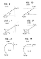
- Circular interpolation (Arc with a designated radius, Fig. 3) G02 (G03) Xx1 Yy1 Rr1 Ff1;
- Circular interpolation (Arc with designated coordinates of the arc center, Fig. 4) G02 (G03) Xx1 Yy1 li1 Jj1 Ff1.
- Figs. 2 through 4 are illustrative of Examples 1 through 3, and designated at x0, y0 are the coordinates of a starting point, x1, y1 the coordinates of an ending point, r1 a radius, i1, j1 the coordinates of the arc center.
- f1 represents the feed speed.
- Example 1 where the straight line of Example 1 shown in Fig. 2 is to be defined, there are employed a symbol G01 which indicates a straight line, the coordinates Xx1, Yy1 of an ending point of the line, and a feed speed Ff1 for the tool.
- the arcs can be defined in a similar manner.
- Symbols G02, G03 used in Examples 2, 3 are G codes indicating arcs or circular interpolation.
- the code G02 represents clockwise rotation of the tool, and the code G03 represents counterclockwise rotation of the tool. Therefore, the arrowheads on the arcs illustrated in Figs. 3 and 4 indicate the code G02 (clockwise rotation).
- Fig. 3 two arcs are plotted which interconnect the starting point (x0, y0) and the ending point (x1, y1 These two arcs are distinguished by whether the sign of the radius is positive or negative. If the sign of the radius is positive, then the arc to be drawn is smaller than a semicircle, and if the sign of the radius is negative, then the arc is greater than a semicircle.
- graphic patterns have been defined by entering G codes having various meanings, the coordinates of the ending points of the lines, tool feed speeds, and arc radii in the form of numerical information as illustrate in Examples 1 through 3.
- Figs. 5 and 6 There have been known methods (shown in Figs. 5 and 6) for defining the machining position- ings for a tool as a group of points.
- the definition of such machining positions as a group of points is employed for an NC apparatus for driving a machine tool such as a machining center to bore or tap a workpiece at the positions indicated by the group of points.
- Fig. 5 is illustrative of a group of points entered as arranged in a row
- Fig. 6 is illustrative of a group of points entered as arranged in a grid-like pattern.
- G35 is a G code for designating a line at an angle, meaning a straight line inclined at a prescribed angle with respect to a reference line.
- Designated at X, Y are addresses indicative of the coordinates of a starting point, I an address indicative of the pitch or point-to-point interval t1, J an address indicative of the angle 81 formed between the line passing through the row of points and the X axis, and K is an address representing the number of machining positions required.
- G37 is a G code designating a grid, and indicates a group of points to be plotted in a grid-like pattern.
- Designated in this information labelled by G37 are X, Y address indicating the coordinates of a starting point, I an address indicative of the pitch or point-to-point interval in the direction of the X axis, P an address representative of the number of machining positions in the X-axis direction, J an address representing the pitch or point-to-point interval in the direction of the Y axis, and K an address representative of the number of machining positions in the Y-axis direction.
- Another object of the present invention is to provide a method for defining graphic patterns for a NC apparatus which is capable of easily checking the data entered.
- Still another object of the present invention is to provide a method capable of defining graphic patterns in a NC apparatus without having to find the coordinates of an ending point prior to the data being entered in the NC apparatus.
- the object of the invention is solved by a method for defining graphic patterns in a NC apparatus as indicated above, comprising the following steps:
- a method for defining graphic patterns in a NC apparatus comprising display means, display control means, data setting means, a memory, computing means, central processing means and output control means.
- the display control means controls the display means to display, as head items, addresses comprising the designation of a straight line or an arc for a planar graphic pattern, a vector angle of the straight line or a radius of the arc, the vector components of the straight line or coordinates of the center of the arc, and modifiers.
- the data setting means sets known data by successively or appropriately using addresses displayed on the display means and indicative of the straight line and the arc derived from the planar graphic pattern.
- the memory stores the addresses, the data set by the data setting means, and formulas.
- the computing means computes the set data stored in the memory according to the formulas to determine the addresses of unknown data which have not been given numerical values by the data setting means.
- the central processing means controls the computing means and the memory to store the results of computation effected by the computing means.
- the output control means is responsive to the set data and computed data stored in the memory and controls the movement of a tool of a machine tool.
- the NC apparatus includes an input unit 101 to which commands are supplied from an external source, a display unit 102 such as a CRT (cathode-ray tube), a display control unit 103 for controlling the display on the CRT 102, and a means 104 such as a keyboard for setting known data successively or appropriately using the addresses displayed on the CRT 102.
- a display unit 102 such as a CRT (cathode-ray tube)
- a display control unit 103 for controlling the display on the CRT 102
- a means 104 such as a keyboard for setting known data successively or appropriately using the addresses displayed on the CRT 102.
- the NC apparatus also has a central processing unit 105, a memory 106 for storing various information and data such as the addresses to be displayed on the CRT 102, data set by the data setting means 104, and formulas for calculating data from the set data, and a computing unit 107 operable under the control of the central processing unit 105 for computing unknown data which have not been given numerical values, based on the set data and the formulas stored in the memory 106, and for storing the computed data in the memory 106.
- a central processing unit 105 for storing various information and data such as the addresses to be displayed on the CRT 102, data set by the data setting means 104, and formulas for calculating data from the set data
- a computing unit 107 operable under the control of the central processing unit 105 for computing unknown data which have not been given numerical values, based on the set data and the formulas stored in the memory 106, and for storing the computed data in the memory 106.
- NC apparatus system thus constructed for defining a graphic pattern to be followed by the tool of the machine tool device will first be described.
- address items required for such graphic pattern definition and stored in the memory 106 are first displayed as head items on the CRT 102 under the control of the display control unit 103.
- the graphic pattern is defined at this time as a straight line or an arcuate line, the head items as displayed being shared by the straight and arcuate line designations.
- the head items necessary for defining a graphic pattern are: which are displayed on the CRT 102 as such.
- the head items displayed as respective addresses on the CRT have the following definitions:
- the column marked with "NO”, indicates conditions in which the data entered by the data setting means 104 are sufficient for defining a graphic pattern, the conditions being classified into the three groups A, B and C:
- the column for the G code has the same content as the address EL, in which 1 designates a straight line, 2 a CW (clockwise rotation) arc, and 3 a CCW (counterclockwise rotation) arc.
- the symbol “0" indicates data input, "?” data which have not been given numerical values, and "--->" a cursor skip.
- Graphic patterns given by the types A-1 through A-11, B-1 through B-5, and C-1 through C-6 are illustrated in Figs. 2 through 4 and 9 through 27, respectively.
- the pattern types A-1, A-6, and A-7 have the same address as those used by the conventional graphics definition method, and have the same graphic patterns as shown in Figs. 2, 3, and 4, respectively.
- Figs. 2 through 4 and 9 through 16 illustrate graphic patterns belonging to the A types (capable of defining graphic patterns with only the data entered).
- the graphic patterns shown in Figs. 2 and 9 through 12 relate to straight lines.
- the graphic pattern (A-1) shown in Fig. 2 is given the coordinates of an ending point in the same manner as the conventional method of defining a graphic pattern.
- Figs. 9 through 12 illustrate methods of defining graphic patterns added according to the present invention.
- Each of the graphic patterns of Fig. 9(A-2) and Fig. 10(A-3) is given one of the coordinates of an ending point and a vector angle
- each of the graphic patterns of Fig. 11(A-4) and Fig. 12(A-5) is given one of the coordinates of an ending point and vector components.
- the unknown coordinates in the patterns (A-2), (A-3) shown in Figs. 9 and 10 can be determined by the computing unit 107 through arithmetic operations on the set values or known coordinates of the ending points and the vector angles.
- the unknown coordinates in the patterns (A-4), (A-5) shown in Figs. 11 and 12 can be determined through arithmetic operations on the set values or known coordinates of the end points and the vector components.
- Figs. 3 and 4 and 13 through 16 illustrate arcuate lines.
- the graphic pattern shown in Fig. 3(A-6) is the same as a conventional arc with a designated radius
- the graphic pattern shown in Fig. 4(A-7) is the same as a conventional arc with a designated arc center.
- These patterns are given the coordinates of ending points and radii (with a positive or a negative sign) or the coordinates of arc centers.
- Figs. 13 through 16 are illustrative of methods for defining graphic patterns, added according to the present invention.
- each of the graphic patterns shown in Fig. 15(A-10) and Fig. 16(A-11) is given one of the coordinates of an arc center and the coordinates of an ending point.
- the unknown coordinates of the ending points and arc centers in the graphic patterns defined in Figs. 13 through 16 can be computed by the computing unit 107 from the data set by the data setting means 104 (given values) and stored in the memory 106 using mathematical formulas.
- Figs. 17 through 21 illustrate graphic patterns belonging to the B type (incapable of defining a graphic pattern with only the data entered, but rendered capable of defining a graphic pattern using the data on the next following line).
- These illustrated methods of defining graphic patterns can be added according to the present invention. In all of these methods, no coordinates of the ending points are given and the modified P is employed.
- Figs. 17 and 19 show straight lines.
- the graphic pattern of Figs. 17(B-1) is given a vector angle
- the graphic pattern of Fig. 18(B-2) is given vector components.
- the graphic pattern shown in Fig. 19(B-3) is used only when the line will contact an arc, and is given no vector angle and no vector components.
- Figs. 20 and 21 illustrate arcs.
- the graphic pattern of Figs. 20(B-4) is given only the coordinates of the arc center, and the graphic pattern of Fig. 21(B-5) is given only the radius.
- the B-type graphic patterns shown in Figs. 17 through 21 remain unspecified as they are, and do not supply enough information as to the coordinates, etc. to permit the tool to follow the required paths.
- These graphic patterns can be completely defined on the basis of data for the next following line. Therefore, the coordinates of the ending point are found by the computing unit 107 through computations using the data for the next following line, to thereby define the desired graphic patterns.
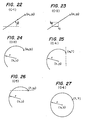
- Figs. 22 through 27 show graphic patterns belonging to the C type (having more data entered than necessary for defining the immediate graphic pattern, the entered data being required for defining previous and following graphic patterns). These graphic patterns can be added according to the present invention, and employ the modifier P.
- the patterns shown in Figs. 22 and 23 are directed to straight lines.
- Each of the graphic patterns shown in Fig. 22(C-1) and Fig. 23(C-2) is given the coordinates of an ending point, a vector angle or vector components.
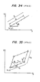
- the patterns of Figs. 24 through 27 are arcuate lines.
- the graphic pattern of Fig. 24(C-3) is given the coordinates of an ending point, a radius, and the coordinates of the arc center.
- Each of the graphic patterns illustrated in Fig. 25(C-4) and Fig. 26(C-5) is given one of the coordinates of an ending point, a radius, and the coordinates of the arc center.
- the graphic pattern shown in Fig. 27(C-6) is given a radius and the coordinates of the arc center.
- graphic figures can be defined by various patterns.
- the coordinates of the ending points can be computed on the basis of the set data defined.
- the coordinates of the ending points can be computed on the basis of the set data defined by the other pattern types, as described in the examples below.
- any machining path for the tool of the machine tool can be defined as a desired graphic figure or pattern composed of the combination of the various patterns described above.
- the tool can be moved under the control of the set data and the computed data stored in the memory 106.
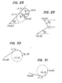
- FIG. 8 Examples of combinations of the graphics definition patterns shown in Fig. 8 are illustrated in Figs. 28 through 31.
- Fig. 28 shows a graphic pattern which is a combination of the patterns illustrated in Fig. 17(B-1) and Fig. 3(A-6).
- a data input example is as follows:
- X, Y are the coordinates of an end point, and R/8 the radius (arc) or vector angle (straight line).
- This data input can be effected by setting the known data on the data setting means 104 while watching the addresses displayed on the CRT 102. At this time, the known data are entered assuming knowledge of the machining path of the tool.
- Fig. 29 shows a graphic pattern which is a combination of the patterns illustrated in Fig. 17(B-1) and Fig. 22(C-1).
- a data input example is as follows:
- Fig. 30 shows a graphic pattern which is a combination of the patterns illustrated in Fig. 19(B-3) and Fig. 4(A-7).
- a data input example for a CW arc is as follows:
- Fig. 31 shows a graphic pattern similar to that of Fig. 30, but the direction of rotation along the arc is different.
- a data input example for a CCW arc is as follows:
- any graphic pattern to be defined is divided into straight and arcuate lines which are designated without having to specify the coordinates of ending points as has been conventional.
- the known data on a straight line can be set by successively or appropriately using addresses of ending point coordinates (X, Y), a vector angle 8, vector components (I, J), and a modifier.
- Known data on an arc can be set by successively or appropriately using addresses of ending point coordinates (X, Y), a radius R, coordinates (I, J) of an arc center, and a modifier P.
- a total of six addresses are used. Any unknown data which have not been given numerical values are computed using the known data.
- Data can be established by successively or appropriately setting known data or data that can easily be determined in accordance with addresses while referring to the graphics definition patterns given in the table of Fig. 8. Accordingly, any graphic pattern can be defined without determining any ending point coordinates.
- addresses displayed on the display unit are given as head items shared by straight and arcuate lines, they may be differently displayed respectively for straight and arcuate lines as follows: Straight lines: Arcuate lines:
- any planar graphic pattern can be defined without previously determining any point coordinates since the ending point coordinates can be later computed using other data.
- addresses can be displayed in advance for easier data input for graphic pattern definition than in conventional arrangements, in which the numerical data and addresses were simultaneously specified.
- Such are grouped into patterns, and such patterns are selected and data set through the data setting means 104 according to head items or addresses displayed on the CRT 102.
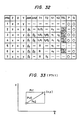
- Fig. 32 illustrates the addresses displayed as head items on the CRT 102, there being ten addresses and three modifiers.
- the ten addresses shown in Fig. 32 are PTN, Z, X, Y, AN1, AN2, T1, T2, Na, and N2, and the three modifiers are TSL, P, and Q. These modifiers allow conditions to be selectively designated for an increased number of shapes to be established.
- the point group patterns PTN include a pattern PTN1 composed of a point, a pattern PTN2 of a row of point, a pattern PTN3 of a rhombus, a pattern PTN4 of a grid-like rhombus, a pattern PTN5 of a circle, a pattern PTN6 of an arc, and a pattern PTN7 of a chord.
- Designated at Z is the depth of cut and at X, Y the coordinates of a reference point.
- the coordinates X, Y indicate those of the first point for the patterns of the point, row of points, rhombus, and grid-like rhombus, and indicate those of the arc center for the patterns of the circle, arc, and chord.
- the address AN1 represents an angle 81 with a reference axis (X axis), specifying a first direction
- the address AN2 represents an angle 82 with the reference axis (X axis) or the first direction, specifying a second direction.
- the address T1 indicates the pitch t1 or the entire length 11 in the first direction for the pattern of the row of points, rhombus, and grid-like rhombus, and the radius R for the patterns of the circle, arc, and chord.
- the address T2 is representative of the pitch t1 orthe entire length 11 in the second direction for the patterns of the rhombus and grid-like rhombus, andthe chord length forthe chord pattern.
- the address N1 is indicative of the number n1 of machining positions in the first direction for the patterns of the row of points, rhombus, and grid-like rhombus, and the number n1 of machining positions for the patterns of the circle and arc.
- the address N2 represents the number n2 of machining positions in the second direction for the patterns of the rhombus or grid-like rhombus. In each machining position, the workpiece is bored or tapped by the tool. Therefore, the depth of the cut can be specified as an address.
- the modifier TSL serves to affect the point patterns of the row of points, rhombus, grid-like rhombus, and arc, and selects an incremental command (INC) or an absolute command (ABS).
- an incremental command is expressed by the pitch or a point-to-point interval between adjacent points on a straight line
- an absolute command is expressed by the entire length equal to the distance between the first point and the final point.
- an incremental command is defined as an angleformed between two adjacent points
- an absolute command is defined as an angle formed between the reference axis (X axis) or a straight line in the first direction and the final point.
- the modifier P is effective in affecting the point patterns of point, rhombus, and grid-like rhombus patterns.
- the modifier P selects one of three tool paths leading to a reference point.
- the modifier P determines whetherthe four corners are to be bored or not.
- the modifier P selects an orientation for a boring position with respect to a straight line in the first direction indicated by the angle with the reference axis (X axis).
- the modifier Q is effective in affecting the point patterns of point, row of points, rhombus, grid-like rhombus, and arc patterns, by determining whether the first point is to be used only for positioning or is to be bored.
- Fig. 33 shows a shape defined by the pattern PTN1 (point).
- the pattern PTN1 displayed as an address item on the CRT 102 is selected through the data setting means 104.
- the cut depth Z is established as required, and the coordinates of a reference point, that is, point coordinates X, Y are established through the data setting means 104.
- the tool moves along a predetermined one of the tool paths. Any desired one of the tool paths can be selected by selecting and setting modifier P through the data setting means 104.
- the pattern PTN2 displayed as an address item on the CRT 102 is selected by the data setting means 104, and then the address items such as the cut depth Z, the reference point coordinates X, Y, the angle 81, the pitch t1, and the number n1 of machining positions are established.
- Fig. 34 shows an instance in which a row of points is set using the entire length 11 of the row. The other data are selected and set in the same manner as where the row of points is defined using the pitch t1.
- a row of points is normally defined by either the mode of Fig. 5 in which the pitch t1 is employed or the mode of Fig. 34 in which the entre length 11 is used. These modes can be selected as desired by employing the modifier TSL.
- Fig. 35 is illustrative of a pattern PTN (rhombus) as defined by pitches t1, t2.
- the pattern PTN3 displayed as an address item on the CRT 102 is selected.
- the address items such as the cut depth Z, the reference point coordinates X, Y, the angles 81, 82, the pitches t1, t2, and the numbers n1, n2 of machining positions are established.
- the operator enters these data settings thgough the data setting means 104 while watching the CRT 102, the entered data being stored in the memory 106.
- the computing unit 107 is controlled by the central processing unit 105 to effect arithmetic operations on the stored data according to formulas stored in the memory 106to thereby compute the coordinates of the machining positions other than the reference point.
- the computed coordinates are then stored in the memory 106.
- the tool of the machine tool is then moved according to the machining position coordinate data stored in the memory 106.
- a point pattern of a rhombus is to be defined, it can be defined using the entire lengths 11, 12 in the same manner as that of the pattern PTN2 (row of points). Either of the pitch-based or length-based rhombus definitions can be selected as desired by the use of the modifier TSL.
- the same procedure as described above is followed. More specifically, the pattern PTN (rhombus) displayed as an address item on the CRT 102 is selected as the pattern, and the reference point and other necessary address items are set through the data setting means 104. The coordinates of machining positions other than the reference point for the selected pattern are then computed by the computing unit 107, and the computed coordinates are stored in the memory 106 to thereby define a point group graphic pattern. The tool can be moved according to the coordinates stored in the memory 106 up to the defined point group positions.
- PTN rhombus
- Fig. 36 illustrates a grid-like rhombus pattern PTN4 selected as a point group pattern and defined by the pitches t1, t2.
- the grid-like rhombus pattern can also be defined using the entire lengths 11, 12. Normally, one of these modes is always used. However, the modes can be selectively used via the modifier TSL.
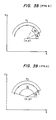
- Figs. 38 and 39 are illustrative of patterns defined by the patterns PTN6 (arc).
- the example shown in Fig. 38 is set by the angle 82 formed between two adjacent points in the pattern PTN6 (arc), and the example shown in Fig. 39 is set by the angle 82 formed between the reference axis (X axis) or the straight line in the first direction and the final point in the pattern PTN6 (arc).
- the two can be selectively employed using the modifier TSL.
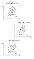
- Figs. 40, 41 and 42 show graphic patterns defined by the pattern PTN7 (chord).
- Fig. 40 illustrates an example in which machining positions are located on both sides of the straight line in the first direction specified by the angle 81.
- Fig. 41 shows an example in which the machining position is located on the lefthand side of the straight line, and Fig. 42 shows an example in which the machining position is located on the righthand side.
- PTN7 chord
- Fig. 40 illustrates an example in which machining positions are located on both sides of the straight line in the first direction specified by the angle 81.
- Fig. 41 shows an example in which the machining position is located on the lefthand side of the straight line
- Fig. 42 shows an example in which the machining position is located on the righthand side.
- the modes shown in Figs. 40, 41 and 42 can be selectively used by employing the modifier P.
- Figs. 35 and 36 showing the point group patterns PTN3 (rhombus) and PTN4 (grid-like rhombus), the angle 82 indicating the second direction is given with respect to the first direction specified by the angle 61.
- Fig. 39 showing the pattern PTN6 (arc), the angle 82 up to the final point is defined with respect to the first direction specified by the angle ⁇ 1. However, this angle 82 may be expressed with respect to the reference axis (X axis).
Landscapes
- Engineering & Computer Science (AREA)
- Physics & Mathematics (AREA)
- General Physics & Mathematics (AREA)
- Automation & Control Theory (AREA)
- Human Computer Interaction (AREA)
- Manufacturing & Machinery (AREA)
- Geometry (AREA)
- Numerical Control (AREA)
Claims (14)
gekennzeichnet durch die folgenden Schritte:
Applications Claiming Priority (4)
| Application Number | Priority Date | Filing Date | Title |
|---|---|---|---|
| JP57151475A JPS5941011A (ja) | 1982-08-31 | 1982-08-31 | 数値制御装置の図形定義回路 |
| JP151475/82 | 1982-08-31 | ||
| JP155003/82 | 1982-09-06 | ||
| JP57155003A JPS5945505A (ja) | 1982-09-06 | 1982-09-06 | 数値制御装置の点群の位置定義装置 |
Publications (2)
| Publication Number | Publication Date |
|---|---|
| EP0103789A1 EP0103789A1 (de) | 1984-03-28 |
| EP0103789B1 true EP0103789B1 (de) | 1988-11-30 |
Family
ID=26480713
Family Applications (1)
| Application Number | Title | Priority Date | Filing Date |
|---|---|---|---|
| EP83108580A Expired EP0103789B1 (de) | 1982-08-31 | 1983-08-31 | Verfahen zur Bestimmung grafischer Muster für eine numerische Steuereinrichtung |
Country Status (4)
| Country | Link |
|---|---|
| US (1) | US4556957A (de) |
| EP (1) | EP0103789B1 (de) |
| KR (1) | KR880001306B1 (de) |
| DE (1) | DE3378598D1 (de) |
Families Citing this family (22)
| Publication number | Priority date | Publication date | Assignee | Title |
|---|---|---|---|---|
| JPS60157608A (ja) * | 1984-01-26 | 1985-08-17 | Fanuc Ltd | 数値制御方式 |
| JP2561907B2 (ja) * | 1984-08-24 | 1996-12-11 | 三菱電機株式会社 | 数値制御装置 |
| US4745405A (en) * | 1984-08-31 | 1988-05-17 | International Business Machines Corporation | Object movement feedback |
| JPS61184610A (ja) * | 1985-02-12 | 1986-08-18 | Fanuc Ltd | 移動軌跡描画方式 |
| KR900003123B1 (ko) * | 1985-03-13 | 1990-05-08 | 도시바 기까이 가부시기 가이샤 | 자유표면 평가방법 및 그의 nc 시스템 |
| US4736306A (en) * | 1985-04-29 | 1988-04-05 | The United States Of America As Represented By The United States Department Of Energy | System for conversion between the boundary representation model and a constructive solid geometry model of an object |
| US4891763A (en) * | 1986-04-24 | 1990-01-02 | Brother Kogyo Kabushiki Kaisha | NC program editing and programming device |
| DE3616740A1 (de) * | 1986-05-17 | 1987-11-19 | Heidenhain Gmbh Dr Johannes | Vorrichtung zur gewinnung von werkstueckkonturen |
| JPS63104104A (ja) * | 1986-10-21 | 1988-05-09 | Fanuc Ltd | 自動プログラミングシステム |
| CA1339155C (en) * | 1987-07-28 | 1997-07-29 | David M. Dundorf | Computer produced carved signs and method and apparatus for making same |
| JPH01102605A (ja) * | 1987-10-15 | 1989-04-20 | Fanuc Ltd | 輪郭形状修正方法 |
| JPH01152511A (ja) * | 1987-12-09 | 1989-06-15 | Fanuc Ltd | 自動プログラミングにおける図形定義方式 |
| JPH01163803A (ja) * | 1987-12-21 | 1989-06-28 | Fanuc Ltd | 組合せ形状定義方式 |
| JPH01287707A (ja) * | 1988-05-16 | 1989-11-20 | Mitsubishi Electric Corp | 数値制御装置の加工データの作成方法 |
| US4935865A (en) * | 1988-06-02 | 1990-06-19 | The United States Of America As Represented By The Secretary Of The Air Force | Computer controlled electropolishing system |
| JPH0215304A (ja) * | 1988-07-04 | 1990-01-19 | Mitsubishi Electric Corp | 数値制御情報作成方法 |
| US5028180A (en) * | 1989-09-01 | 1991-07-02 | Sheldon Paul C | Six-axis machine tool |
| JP2830407B2 (ja) * | 1990-07-13 | 1998-12-02 | 三菱電機株式会社 | 曲線抽出装置およびncプログラミングシステム |
| US5538373A (en) * | 1992-02-20 | 1996-07-23 | Giddings & Lewis, Inc. | Machine tool vibration isolation system |
| US5388935A (en) * | 1993-08-03 | 1995-02-14 | Giddings & Lewis, Inc. | Six axis machine tool |
| US5940180A (en) * | 1994-10-11 | 1999-08-17 | Giddings & Lewis | Laser interferometer measurement system for use with machine tools |
| JP4175115B2 (ja) * | 2001-05-11 | 2008-11-05 | 和光純薬工業株式会社 | フッ素置換トリフェニルスルホニウム塩 |
Family Cites Families (7)
| Publication number | Priority date | Publication date | Assignee | Title |
|---|---|---|---|---|
| US4010356A (en) * | 1974-10-15 | 1977-03-01 | Do All Company | Tape preparation system |
| US4115858A (en) * | 1976-01-12 | 1978-09-19 | Houdaille Industries, Inc. | Machine tool controller employing microprocessor system for controlling Z axis |
| US4152765A (en) | 1977-09-15 | 1979-05-01 | Weber John M | Programmer unit for N/C systems |
| JPS5486887A (en) * | 1977-12-22 | 1979-07-10 | Toyoda Mach Works Ltd | Numerical controller |
| JPS56168223A (en) * | 1980-05-28 | 1981-12-24 | Fanuc Ltd | Numerical value control system |
| JPS5719809A (en) * | 1980-07-10 | 1982-02-02 | Fanuc Ltd | Numerical control information generating system |
| US4328550A (en) * | 1980-08-08 | 1982-05-04 | Weber John M | Programmer unit with composite calculation capability |
-
1983
- 1983-08-13 KR KR1019830003795A patent/KR880001306B1/ko not_active Expired
- 1983-08-30 US US06/527,719 patent/US4556957A/en not_active Expired - Lifetime
- 1983-08-31 DE DE8383108580T patent/DE3378598D1/de not_active Expired
- 1983-08-31 EP EP83108580A patent/EP0103789B1/de not_active Expired
Non-Patent Citations (1)
| Title |
|---|
| NUMERICAL CONTROL SOCIETY, PROCEEDINGS OF THE ANNUAL MEETING AND TECHNICAL CONFERENCE, 31st March - 3rd April 1974, Proc. 11: M.A. de Vries: international future of NC/CAM; C.S.HUTCHINS: "Part boundary. A quantum increase in shape description and cutting capability", pp. 229-241 * |
Also Published As
| Publication number | Publication date |
|---|---|
| US4556957A (en) | 1985-12-03 |
| KR840006083A (ko) | 1984-11-21 |
| KR880001306B1 (ko) | 1988-07-22 |
| EP0103789A1 (de) | 1984-03-28 |
| DE3378598D1 (en) | 1989-01-05 |
Similar Documents
| Publication | Publication Date | Title |
|---|---|---|
| EP0103789B1 (de) | Verfahen zur Bestimmung grafischer Muster für eine numerische Steuereinrichtung | |
| US6073058A (en) | Computer generated graphic depiction of manual machining operations | |
| US4530046A (en) | Method of inputting machining information to a machine tool numerical controller and apparatus therefor | |
| US5127140A (en) | Numerically-controlled lathe, numerically-controlled device therefor and processing procedure thereby | |
| CA1243380A (en) | Method and apparatus for producing numerical control programs | |
| US5150305A (en) | Numerical control system providing graphic machining simulation | |
| US4604705A (en) | Numerical control machining method and system therefor | |
| JPH0238342B2 (de) | ||
| KR850000328B1 (ko) | 수치 제어방법 | |
| KR860002004B1 (ko) | 수치제어가공 방식 | |
| US4700313A (en) | Plural turret system with display of permitted and non-permitted simultaneous machining operations | |
| US5315503A (en) | Numerical control apparatus having a teaching function and a method of teaching a machining program thereby | |
| US4648025A (en) | Interactive numerical controller for a machine tool | |
| Madison | CNC machining handbook: basic theory, production data, and machining procedures | |
| KR890003118B1 (ko) | 수치제어장치가 붙은 선반에 의한 공구표시 방법 | |
| CN100399340C (zh) | 用于生成加工程序的方法和装置 | |
| JPH0565886B2 (de) | ||
| JP4059411B2 (ja) | Nc工作機械の制御装置 | |
| EP0529239B1 (de) | Numerische Steuerungseinheit mit Positionszählersteuerung und Anzeige | |
| JPS6361126B2 (de) | ||
| US5060163A (en) | Programming apparatus for lathes | |
| CN103076760A (zh) | 一种滑槽的铣削加工方法 | |
| KR100235904B1 (ko) | 가공 장치 | |
| Sirinterlikci et al. | Computer-Aided Manufacturing (CAM) | |
| JPS6048229A (ja) | 複合加工工作機械 |
Legal Events
| Date | Code | Title | Description |
|---|---|---|---|
| PUAI | Public reference made under article 153(3) epc to a published international application that has entered the european phase |
Free format text: ORIGINAL CODE: 0009012 |
|
| AK | Designated contracting states |
Designated state(s): DE FR GB IT |
|
| 17P | Request for examination filed |
Effective date: 19840524 |
|
| ITF | It: translation for a ep patent filed | ||
| GRAA | (expected) grant |
Free format text: ORIGINAL CODE: 0009210 |
|
| AK | Designated contracting states |
Kind code of ref document: B1 Designated state(s): DE FR GB IT |
|
| REF | Corresponds to: |
Ref document number: 3378598 Country of ref document: DE Date of ref document: 19890105 |
|
| ET | Fr: translation filed | ||
| PLBE | No opposition filed within time limit |
Free format text: ORIGINAL CODE: 0009261 |
|
| STAA | Information on the status of an ep patent application or granted ep patent |
Free format text: STATUS: NO OPPOSITION FILED WITHIN TIME LIMIT |
|
| 26N | No opposition filed | ||
| ITTA | It: last paid annual fee | ||
| PGFP | Annual fee paid to national office [announced via postgrant information from national office to epo] |
Ref country code: FR Payment date: 19920820 Year of fee payment: 10 |
|
| PG25 | Lapsed in a contracting state [announced via postgrant information from national office to epo] |
Ref country code: FR Effective date: 19940429 |
|
| REG | Reference to a national code |
Ref country code: FR Ref legal event code: ST |
|
| REG | Reference to a national code |
Ref country code: GB Ref legal event code: 746 Effective date: 19950810 |
|
| PGFP | Annual fee paid to national office [announced via postgrant information from national office to epo] |
Ref country code: DE Payment date: 20010828 Year of fee payment: 19 |
|
| PGFP | Annual fee paid to national office [announced via postgrant information from national office to epo] |
Ref country code: GB Payment date: 20010830 Year of fee payment: 19 |
|
| REG | Reference to a national code |
Ref country code: GB Ref legal event code: IF02 |
|
| PG25 | Lapsed in a contracting state [announced via postgrant information from national office to epo] |
Ref country code: GB Free format text: LAPSE BECAUSE OF NON-PAYMENT OF DUE FEES Effective date: 20020831 |
|
| PG25 | Lapsed in a contracting state [announced via postgrant information from national office to epo] |
Ref country code: DE Free format text: LAPSE BECAUSE OF NON-PAYMENT OF DUE FEES Effective date: 20030301 |
|
| GBPC | Gb: european patent ceased through non-payment of renewal fee |
Effective date: 20020831 |