EP0103687B1 - Plate holder for tampon printing machines - Google Patents
Plate holder for tampon printing machines Download PDFInfo
- Publication number
- EP0103687B1 EP0103687B1 EP83106687A EP83106687A EP0103687B1 EP 0103687 B1 EP0103687 B1 EP 0103687B1 EP 83106687 A EP83106687 A EP 83106687A EP 83106687 A EP83106687 A EP 83106687A EP 0103687 B1 EP0103687 B1 EP 0103687B1
- Authority
- EP
- European Patent Office
- Prior art keywords
- printing block
- receiver
- printing
- base member
- holder according
- Prior art date
- Legal status (The legal status is an assumption and is not a legal conclusion. Google has not performed a legal analysis and makes no representation as to the accuracy of the status listed.)
- Expired
Links
Images

Classifications
-
- B—PERFORMING OPERATIONS; TRANSPORTING
- B41—PRINTING; LINING MACHINES; TYPEWRITERS; STAMPS
- B41F—PRINTING MACHINES OR PRESSES
- B41F17/00—Printing apparatus or machines of special types or for particular purposes, not otherwise provided for
- B41F17/001—Pad printing apparatus or machines
-
- B—PERFORMING OPERATIONS; TRANSPORTING
- B41—PRINTING; LINING MACHINES; TYPEWRITERS; STAMPS
- B41F—PRINTING MACHINES OR PRESSES
- B41F27/00—Devices for attaching printing elements or formes to supports
- B41F27/08—Devices for attaching printing elements or formes to supports for attaching printing formes to flat type-beds
Definitions
- the invention relates to a plate holder for pad printing machines with a plate-shaped base body, which has a recessed ink reservoir on its top parallel to the back and in the area lying in front of the ink reservoir has a receptacle with clamping devices that is matched to the dimensions of the plate.
- a pad printing machine using such plate holders is described in DE-AS 1 939437 and FR-A 2388679. It is aligned with each other in the top of the base body, the ink reservoir and the plate holder are simply recessed as recessed recesses.
- the dimensions of the cliché holder are precisely matched to the dimensions of the cliché. This configuration of the plate holder therefore means that a separate plate holder is required for each plate size. With a large number of different sizes of the clichés, this is a considerable effort and, in addition, when changing the cliché there is usually also the change of the cliché holder, which also results in unnecessarily long changeover times.
- the ink supply pan and the plate holder each have a constant cross-section over the entire width of the base body and that the width of the ink tank and plate holder can be limited to the width of the plate used by means of two clamping strips, the Bottom sides of the terminal strips are designed for the contour of the top of the base body and are provided with a flexible, solvent-resistant sealing layer.
- the base body is designed so that it can be adjusted to any width of clichés using the two adjustable clamping bars.
- the terminal strips seal the variable ink supply tray, which is automatically adjusted to the size of the clichés used.
- a clear sealing and setting of the cliché in the area of the top of the base body is obtained in that the cliché holder is groove-shaped and has a depth that is greater than the thickness of the clichés used, that pressure bolts are arranged in the bottom of the cliché holder, which are adjustable by means of set screws against the clichés, that the top of the cliché is flush with the upper sides of the adjacent groove walls of the cliché holder and that the clamping strips in the area of the cliché cover and seal the edges of the cliché.
- a continuous height adjustment of the pressure bolts when the plate holder is mounted in the tampon printing machine is made possible according to one embodiment in that the pressure bolts have a transverse wedge receptacle into which a wedge tip of an adjusting screw can be inserted and that the adjusting screws can be screwed into threaded receptacles of the base body, which are screwed into the front of the base body Basic body are embedded horizontally.
- a simple adaptation of the cliché holder to different dimensions in the depth of the base body is achieved according to one embodiment in that the ink supply trough is trapezoidal in cross-section and that the wall of the ink supply trough facing the cliché holder is designed as a bar that can be adjusted in depth with the base body the wall facing away from the ink reservoir forms the groove wall of the plate holder.
- the bracing of the cliché used in the cliché holder is achieved according to one embodiment in that the groove wall of the cliché holder facing away from the ink reservoir is formed by means of a profile strip attached to the front, which forms a receptacle with the groove bottom and partially covers the facing edge of the cliché used and that the profile bar receives a pressure bar in the receptacle formed, which can be clamped against the cliché used by means of pressure screws adjustable in the profile bar.
- the terminal strips have recessed receptacles for fastening screws at the ends, that the terminal strips enclose the front and rear of the base body by means of flanges, and that the fastening screws in thread receptacles of clamping blocks can be screwed in, which engage behind the underside of the base body.
- a further embodiment provides that the base body has a continuous receiving groove on the underside in the region of the front and rear, into which guide approaches of the clamping blocks engage.
- the grooves of the base body and the guide lugs of the clamping blocks are designed as halves of a dovetail connection.
- the plate holder according to the invention has a plate-shaped base body 10.
- a color supply pan 21 with a trapezoidal cross section is continuously introduced, as can be seen from the walls 11 and 23 and the bottom 22.
- the plate holder 35 is also continuously inserted in front of this continuous ink supply tank 21, the area of the base body 10 which forms the wall 11 for the ink supply tank 21 also forming a groove wall of the groove-shaped plate holder 35.
- the depth of the plate holder 35 is greater than the thickness of the plate.
- the cliché 20 used as indicated in FIG. 2, can have different widths with the same dimensions in the depth of the base body 10, as the clichés 20 'and 20 "shown in dashed lines indicate.
- the front groove wall of the plate holder 35 is not formed by the base body 10.
- a profile strip 16 is attached to the front of the base body 10, which partially covers the plate holder 35 and itself forms a holder for pressure strips 12.
- These pressure strips 12 form the groove wall of the groove-shaped plate holder 35 and can be adjusted by means of the pressure screws 15 adjustable in the profile strip 16.
- the plate 20 used can thus be clamped against the fixed rear groove wall of the plate holder 35. Before this, the plate 20 is adjusted in height by means of the pressure bolts 13 arranged in the bottom of the plate holder 35 such that the upper side of the plate 20 is flush with the upper side of the wall 11 and the rising surface of the profile strip 16.
- the pressure bolts 13 are provided with a transverse wedge receptacle 26, into which a wedge tip of the set screw 14 is inserted.
- the set screws 14 are screwed into threaded receptacles 27 of the base body 10, which are introduced horizontally into the front of the base body 10.
- the profile strip 16 has bores 31 which allow access to the threaded receptacles 27.
- the pressure pins 13 can be adjusted in height from the front of a plate holder fixed in the pad printing machine. Only the set screws 14 need to be screwed more or less into the threaded receptacles 27.
- the wedge tips of the adjusting screws 14 inserted into the wedge receptacles 26 of the pressure bolts 13 then raise the pressure bolts 13 more or less accordingly.
- the cliché 20 lying on the pressure pin 13 is adjusted accordingly.
- the wall 11 of the ink supply trough 21 can also be part of a strip which can be fixed at different distances from the front of the base body 10.
- the plate holder 35 can thus also be adapted in the depth of the base body 10 to different dimensions of the plate 20 'and 20 ". In many cases it has proven sufficient if the bar can be adjusted in stages 5 are attached to the underside of the bar and the base body 10 carries recess 25 for these projections 24 at different distances from the front in the top side. The rest of the construction of the printing plate holder according to FIG. 5 does not differ from the construction of the printing plate holder according to FIG and 3.
- the width of the ink supply tray 21 is automatically adapted to the width of the cliché 20 used by means of two clamping strips 17 according to FIGS. 3 and 6.
- the undersides of the terminal strips 17, which carry a flexible, solvent-resistant sealing layer 19, are matched to the contour of the upper side of the base body 10. Therefore, the continuous ink supply pan 21 is closed on both sides by the terminal strips 17.
- the clamping strips 17 cover the edges of the plate 20 and therefore seal in the area of the top of the plate 20, as can be seen from the section according to FIG. 4.
- the flush transition from the cliché 20 to the wall 11 and to the rising part of the profile strip 16 is ensured and a clear seal is ensured.
- the clamping strips 17 encompass the base body 10 with the flanges 34. Stepped receptacles 28 for the fastening screws 30 are introduced into the flanges 34.
- the fastening screws 30 can be screwed into the threaded receptacles 29 of clamping blocks 18.
- the clamping blocks 18 carry guide lugs 36 which engage in receiving grooves 33 on the underside of the base body 10. These receiving grooves 33 are continuously attached to the front and rear, so that the clamping strips 17 can easily be moved to any position on the base body 10 when the fastening screws 30 are loosened.
- the receiving grooves 33 of the base body 10 and the guide lugs 36 of the clamping blocks 18 form halves of dovetail connections in the exemplary embodiment.
Abstract
Description
Die Erfindung betrifft einen Klischeehalter für Tampondruckmaschinen mit einem plattenförmigen Grundkörper, der auf seiner Oberseite parallel zur Rückseite eine eingelassene Farbvorratswanne und in dem vor der Farbvorratswanne liegenden Bereich eine auf die Abmessungen des Klischees abgestimmte Aufnahme mit Klemmeinrichtungen aufweist.The invention relates to a plate holder for pad printing machines with a plate-shaped base body, which has a recessed ink reservoir on its top parallel to the back and in the area lying in front of the ink reservoir has a receptacle with clamping devices that is matched to the dimensions of the plate.
Eine Tampondruckmaschine, die derartige Klischeehalter verwendet, ist in der DE-AS 1 939437 und der FR-A 2388679 beschrieben. Dabei ist in die Oberseite des Grundkörpers aufeinander ausgerichtet, die Farbvorratswanne und die Klischeeaufnahme einfach als vertiefte Ausnehmungen eingelassen. Die Klischeeaufnahme ist in den Abmessungen genau auf die Abmessungen des Klischees abgestimmt. Diese Ausgestaltung des Klischeehalters hat daher zur Folge, dass für jede Klischeegrösse ein eigener Klischeehalter erforderlich ist. Dies ist bei einer Vielzahl von verschiedenen Grössen der Klischees ein beachtlicher Aufwand und zudem kommt bei einem Klischeewechsel meistens auch der Wechsel des Klischeehalters hinzu, was auch unnötig grosse Umrüstzeiten mit sich bringt.A pad printing machine using such plate holders is described in DE-AS 1 939437 and FR-A 2388679. It is aligned with each other in the top of the base body, the ink reservoir and the plate holder are simply recessed as recessed recesses. The dimensions of the cliché holder are precisely matched to the dimensions of the cliché. This configuration of the plate holder therefore means that a separate plate holder is required for each plate size. With a large number of different sizes of the clichés, this is a considerable effort and, in addition, when changing the cliché there is usually also the change of the cliché holder, which also results in unnecessarily long changeover times.
Es ist Aufgabe der Erfindung, einen Klischeehalter der eingangs erwähnten Art zu schaffen, der dauernd mit der Tampondruckmaschine verbunden bleiben kann und in der Lage ist, Klischees der verschiedensten Grössen schnell und leicht auswechselbar aufzunehmen.It is an object of the invention to provide a cliché holder of the type mentioned at the outset, which can remain permanently connected to the pad printing machine and is capable of quickly and easily replacing clichés of the most varied sizes.
Diese Aufgabe wird nach der Erfindung dadurch gelöst, dass sich die Farbvorratswanne und die Klischeeaufnahme jeweils mit gleichbleibendem Querschnitt über die gesamte Breite des Grundkörpers erstrecken und dass die Breite der Farbvorratswanne und der Klischeeaufnahme mittels zweier Klemmleisten auf die Breite des verwendeten Klischees begrenzbar ist, wobei die Unterseiten der Klemmleisten auf die Kontur der Oberseite des Grundkörpers ausgelegt und mit einer flexiblen, lösungsmittelfesten Dichtungsschicht versehen sind.This object is achieved according to the invention in that the ink supply pan and the plate holder each have a constant cross-section over the entire width of the base body and that the width of the ink tank and plate holder can be limited to the width of the plate used by means of two clamping strips, the Bottom sides of the terminal strips are designed for the contour of the top of the base body and are provided with a flexible, solvent-resistant sealing layer.
Der Grundkörper ist dabei so ausgestaltet, dass er mit Hilfe der beiden verstellbaren Klemmleisten auf jede beliebige Breite von Klischees eingestellt werden kann. Dabei übernehmen die Klemmleisten die Abdichtung der variablen Farbvorratswanne, die damit automatisch an die Grösse des eingesetzten Klischees angepasst wird.The base body is designed so that it can be adjusted to any width of clichés using the two adjustable clamping bars. The terminal strips seal the variable ink supply tray, which is automatically adjusted to the size of the clichés used.
Eine eindeutige Abdichtung und Einstellung des Klischees im Bereich der Oberseite des Grundkörpers werden nach einer Ausgestaltung dadurch erhalten, dass die Klischeeaufnahme nutförmig ausgebildet ist und eine Tiefe aufweist, die grösser ist als die Dicke der verwendeten Klischees, dass im Boden der Klischeeaufnahme Andrückbolzen angeordnet sind, die mittels Stellschrauben gegen die Klischees verstellbar sind, dass die Oberseite des Klischees auf die Oberseiten der angrenzenden Nutwände der Klischeeaufnahme bündig einstellbar ist und dass die Klemmleisten im Bereich des Klischees die Ränder desselben überdeckt und abdichtet.According to one embodiment, a clear sealing and setting of the cliché in the area of the top of the base body is obtained in that the cliché holder is groove-shaped and has a depth that is greater than the thickness of the clichés used, that pressure bolts are arranged in the bottom of the cliché holder, which are adjustable by means of set screws against the clichés, that the top of the cliché is flush with the upper sides of the adjacent groove walls of the cliché holder and that the clamping strips in the area of the cliché cover and seal the edges of the cliché.
Eine kontinuierliche Höhenverstellung der Andrückbolzen bei in der Tampondruckmaschine montiertem Klischeehalter wird nach einer Ausgestaltung dadurch ermöglicht, dass die Andrückbolzen eine quergerichtete Keilaufnahme aufweisen, in die eine Keilspitze einer Stellschraube einführbar ist und dass die Stellschrauben in Gewindeaufnahmen des Grundkörpers einschraubbar sind, die in der Vorderseite des Grundkörpers horizontal eingelassen sind.A continuous height adjustment of the pressure bolts when the plate holder is mounted in the tampon printing machine is made possible according to one embodiment in that the pressure bolts have a transverse wedge receptacle into which a wedge tip of an adjusting screw can be inserted and that the adjusting screws can be screwed into threaded receptacles of the base body, which are screwed into the front of the base body Basic body are embedded horizontally.
Eine einfache Anpassung der Klischeeaufnahme an verschiedene Abmessungen in der Tiefe des Grundkörpers wird nach einer Ausgestaltung dadurch erreicht, dass die Farbvorratswanne im Querschnitt trapezförmig ausgelegt ist und dass die der Klischeeaufnahme zugekehrte Wand der Farbvorratswanne als in der Tiefe des Grundkörpers verstellbare Leiste ausgebildet ist, die mit der der Farbvorratswanne abgekehrten Wand die Nutwand der Klischeeaufnahme bildet.A simple adaptation of the cliché holder to different dimensions in the depth of the base body is achieved according to one embodiment in that the ink supply trough is trapezoidal in cross-section and that the wall of the ink supply trough facing the cliché holder is designed as a bar that can be adjusted in depth with the base body the wall facing away from the ink reservoir forms the groove wall of the plate holder.
Dabei kann eine ausreichende stufige Verstellung dadurch sichergestellt sein, dass die Leiste an ihrer Unterseite Ansätze aufweist, die in Vertiefungen des Grundkörpers einführbar sind, und dass die Vertiefungen in verschiedenen Abständen von der Vorderseite des Grundkörpers eingelassen sind.Sufficient stepped adjustment can be ensured in this way that the bottom of the bar has lugs that can be inserted into depressions in the base body and that the depressions are let in at different distances from the front of the base body.
Die Verspannung des eingesetzten Klischees in der Klischeeaufnahme wird nach einer Ausgestaltung dadurch erreicht, dass die der Farbvorratswanne abgekehrte Nutwand der Klischeeaufnahme mittels einer an der Vorderseite angebrachten Profilleiste gebildet ist, die mit dem Nutboden eine Aufnahme bildet und den zugekehrten Rand des eingesetzten Klischees teilweise überdeckt und dass die Profilleiste in der gebildeten Aufnahme eine Andrückleiste aufnimmt, die mittels in der Profilleiste verstellbarer Druckschrauben gegen das eingesetzte Klischee verspannbar ist.The bracing of the cliché used in the cliché holder is achieved according to one embodiment in that the groove wall of the cliché holder facing away from the ink reservoir is formed by means of a profile strip attached to the front, which forms a receptacle with the groove bottom and partially covers the facing edge of the cliché used and that the profile bar receives a pressure bar in the receptacle formed, which can be clamped against the cliché used by means of pressure screws adjustable in the profile bar.
Für die unverschiebbare Festlegung der Klemmleisten an dem Grundkörper des Klischeehalters ist nach einer Ausgestaltung vorgesehen, dass die Klemmleisten an den Enden abgesetzte Aufnahmen für Befestigungsschrauben aufweisen, dass die Klemmleisten mittels Flansche die Vorder- und Rückseite des Grundkörpers einschliessen und dass die Befestigungsschrauben in Gewindeaufnahmen von Spannblöcken einschraubbar sind, die die Unterseite des Grundkörpers hintergreifen.For the immovable fixing of the terminal strips on the base body of the cliché holder, it is provided according to one embodiment that the terminal strips have recessed receptacles for fastening screws at the ends, that the terminal strips enclose the front and rear of the base body by means of flanges, and that the fastening screws in thread receptacles of clamping blocks can be screwed in, which engage behind the underside of the base body.
Zur eindeutigen Abstützung der Spannblöcke an der Unterseite des Grundkörpers sieht eine weitere Ausgestaltung vor, dass der Grundkörper an der Unterseite im Bereich der Vorder- und Rückseite eine durchgehende Aufnahmenut aufweist, in die Führungsansätze der Spannblöcke eingreifen. Dabei sind die Aufnahmenuten des Grundkörpers und die Führungsansätze der Spannblöcke als Hälften einer Schwalbenschwanzverbindung ausgebildet.To provide clear support for the clamping blocks on the underside of the base body, a further embodiment provides that the base body has a continuous receiving groove on the underside in the region of the front and rear, into which guide approaches of the clamping blocks engage. The grooves of the base body and the guide lugs of the clamping blocks are designed as halves of a dovetail connection.
Die Erfindung wird anhand von verschiedenen, in den Zeichnungen dargestellten Ausführungsbeispielen näher erläutert. Es zeigt:
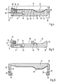
- Fig. 1 in Draufsicht einen Klischeehalter nach der Erfindung,
- Fig. 2 schematisch verschieden grosse Klischees,
- Fig. 3 eine von dem Grundkörper abgenommene Klemmleiste,
- Fig. 4 einen Schnitt durch den Klischeehalter nach Fig. 1, entlang der Linie IV-IV,
- Fig. 5 einen Schnitt ausserhalb der Klemmleisten durch einen anders gestalteten Klischeehalter und
- Fig. 6 einen Schnitt durch die Klemmleiste nach Fig. 3, entlang der Linie VI-VI.
- 1 is a plan view of a plate holder according to the invention,
- 2 schematically different sized clichés,
- 3 shows a terminal strip removed from the base body,
- 4 shows a section through the plate holder according to FIG. 1, along the line IV-IV,
- Fig. 5 shows a section outside of the terminal strips by a differently designed plate holder and
- Fig. 6 shows a section through the terminal block of FIG. 3, along the line VI-VI.
Wie die Fig. 1 und 4 zeigen, weist der Klischeehalter nach der Erfindung einen plattenförmigen Grundkörper 10 auf. Im Bereich der Rückseite ist durchgehend eine im Querschnitt trapezförmige Farbvorratswanne 21 eingebracht, wie die Wände 11 und 23, sowie der Boden 22 erkennen lässt. Vor dieser durchgehenden Farbvorratswanne 21 ist ebenfalls durchgehend die Klischeeaufnahme 35 eingebracht, wobei der Bereich des Grundkörpers 10, der die Wand 11 für die Farbvorratswanne 21 bildet, auch eine Nutwand der nutförmigen Klischeeaufnahme 35 bildet. Die Tiefe der Klischeeaufnahme 35 ist grösser als die Dicke der Klischees. Das eingesetzte Klischee 20 kann, wie in der Fig.2 angedeutet ist, bei gleicher Abmessung in der Tiefe des Grundkörpers 10 verschiedene Breiten aufweisen, wie die gestrichelt gezeichneten Klisches 20' und 20" anzeigen.1 and 4, the plate holder according to the invention has a plate-
Die vordere Nutwand der Klischeeaufnahme 35 wird nicht durch den Grundkörper 10 gebildet. An der Vorderseite des Grundkörpers 10 ist eine Profilleiste 16 angebracht, die die Klischeeaufnahme 35 teilweise überdeckt und selbst eine Aufnahme für Andrückleisten 12 bildet. Diese Andruckleisten 12 bilden die Nutwand der nutförmigen Klischeeaufnahme 35 und sind mittels der in der Profilleiste 16 verstellbaren Druckschrauben 15 verstellbar. Das eingesetzte Klischee 20 kann damit gegen die feststehende hintere Nutwand der Klischeeaufnahme 35 verspannt werden. Vorher wird das Klischee 20 aber mittels der im Boden der Klischeeaufnahme 35 angeordneten Andrückbolzen 13 in der Höhe so eingestellt, dass die Oberseite des Klischees 20 mit der Oberseite der Wand 11 und der ansteigenden Fläche der Profilleiste 16 bündig liegt. Die Andrückbolzen 13 sind mit einer quergerichteten Keilaufnahme 26 versehen, in die eine Keilspitze der Stellschraube 14 eingeführt wird. Die Stellschrauben 14 sind in Gewindeaufnahmen 27 des Grundkörpers 10 eingeschraubt, die horizontal in die Vorderseite des Grundkörpers 10 eingebracht sind. Die Profilleiste 16 hat Bohrungen 31, die den Zugang zu den Gewindeaufnahmen 27 zulassen. Auf diese Weise können die Andrückbolzen 13 von der Vorderseite eines in der Tampondruckmaschine festgelegten Klischeehalters in der Höhe eingestellt werden. Dabei brauchen nur die Stellschrauben 14 mehr oder weniger in die Gewindeaufnahmen 27 eingeschraubt werden. Die in die Keilaufnahmen 26 der Andrückbolzen 13 eingeführten Keilspitzen der Stellschrauben 14 heben die Andrückbolzen 13 dann entsprechend mehr oder weniger an. Das auf dem Andrückbolzen 13 liegende Klischee 20 wird entsprechend mit verstellt.The front groove wall of the
Wie der Schnitt nach Fig. zeigt, kann die Wand 11 der Farbvorratswanne 21 auch Teil einer Leiste sein, die in verschiedenem Abstand zur Vorderseite des Grundkörpers 10 festgelegt werden kann. Damit lässt sich die Klischeeaufnahme 35 auch in der Tiefe des Grundkörpers 10 an verschiedene Abmessungen der Klischees 20' und 20" anpassen. In vielen Fällen hat es sich als ausreichend erwiesen, wenn die Leiste stufig verstellt werden kann. Dazu reicht es aus, wenn an der Unterseite der Leiste Ansätze 24 angebracht sind und der Grundkörper 10 in verschiedenen Abständen zur Vorderseite in die Oberseite eingelassene Vertiefung 25 für diese Ansätze 24 trägt. Der übrige Aufbau des Klischeehalters nach Fig. 5 unterscheidet sich nicht von dem Aufbau des Klischeehalters nach Fig. 1 und 3.As the section according to FIG. 1 shows, the
Wie in Fig. 1 angedeutet ist, wird mittels zweier Klemmleisten 17 nach Fig. 3 und 6 die Breite der Farbvorratswanne 21 automatisch an die Breite des eingesetzen Klischees 20 angepasst. Die Klemmleisten 17 sind mit ihren Unterseiten, die eine flexible, lösungsmittelfeste Dichtungsschicht 19 tragen, an die Kontur der Oberseite des Grundkörpers 10 angepasst. Daher wird die durchgehende Farbvorratswanne 21 beidseitig durch die Klemmleisten 17 geschlossen. Im Bereich des eingesetzten Klischees 20 überdecken die Klemmleisten 17 die Ränder des Klischees 20 und dichten daher im Bereich der Oberseite des Klischees 20 ab, wie aus dem Schnitt nach Fig. 4 zu ersehen ist. Dabei ist der bündige Übergang vom Klischee 20 zu der Wand 11 und zu dem ansteigenden Teil der Profilleiste 16 sichergestellt und eine eindeutige Abdichtung gewährleistet.As indicated in FIG. 1, the width of the
Die Klemmleisten 17 umgreifen den Grundkörper 10 mit den Flanschen 34. In die Flansche 34 sind abgestufte Aufnahmen 28 für die Befestigungsschrauben 30 eingebracht. Die Befestigungsschrauben 30 sind in die Gewindeaufnahmen 29 von Spannblöcken 18 einschraubbar. Die Spannblöcke 18 tragen Führungsansätze 36, die in Aufnahmenuten 33 an der Unterseite des Grundkörpers 10 eingreifen. Diese Aufnahmenuten 33 sind an der Vorder- und Rückseite durchgehend angebracht, so dass die Klemmleisten 17 bei gelockerten Befestigungsschrauben 30 leicht an beliebigen Stellen des Grundkörpers 10 verschoben werden können. Die Aufnahmenuten 33 des Grundkörpers 10 und die Führungsansätze 36 der Spannblöcke 18 bilden im Ausführungsbeispiel Hälften von Schwalbenschwanzverbindungen.The
Claims (9)
Priority Applications (1)
| Application Number | Priority Date | Filing Date | Title |
|---|---|---|---|
| AT83106687T ATE26673T1 (en) | 1982-07-28 | 1983-07-08 | PLATE HOLDER FOR PAD PRINTING MACHINES. |
Applications Claiming Priority (2)
| Application Number | Priority Date | Filing Date | Title |
|---|---|---|---|
| DE3228152A DE3228152C2 (en) | 1982-07-28 | 1982-07-28 | Cliché holder for pad printing machines |
| DE3228152 | 1982-07-28 |
Publications (3)
| Publication Number | Publication Date |
|---|---|
| EP0103687A2 EP0103687A2 (en) | 1984-03-28 |
| EP0103687A3 EP0103687A3 (en) | 1985-09-25 |
| EP0103687B1 true EP0103687B1 (en) | 1987-04-22 |
Family
ID=6169509
Family Applications (1)
| Application Number | Title | Priority Date | Filing Date |
|---|---|---|---|
| EP83106687A Expired EP0103687B1 (en) | 1982-07-28 | 1983-07-08 | Plate holder for tampon printing machines |
Country Status (5)
| Country | Link |
|---|---|
| US (1) | US4491072A (en) |
| EP (1) | EP0103687B1 (en) |
| JP (1) | JPS5924674A (en) |
| AT (1) | ATE26673T1 (en) |
| DE (1) | DE3228152C2 (en) |
Families Citing this family (4)
| Publication number | Priority date | Publication date | Assignee | Title |
|---|---|---|---|---|
| DE8331501U1 (en) * | 1983-11-03 | 1984-02-02 | TAMPOflex GmbH, 7257 Ditzingen | INK FOR A TAMPON PRINTING MACHINE |
| JPH037158Y2 (en) * | 1985-05-07 | 1991-02-22 | ||
| DE4236192A1 (en) * | 1992-01-09 | 1993-07-15 | Martin Grube | |
| KR20140008250A (en) * | 2012-07-10 | 2014-01-21 | 주식회사 엘지화학 | Apparatus for fixing printed matter, printing device and printing method |
Family Cites Families (8)
| Publication number | Priority date | Publication date | Assignee | Title |
|---|---|---|---|---|
| US764517A (en) * | 1901-12-28 | 1904-07-05 | P R Rideout | Stereotype-block. |
| DE489851C (en) * | 1927-10-27 | 1930-01-20 | Chester B Johnson | Support bar for fastening the set on the foundation of high-speed cylinder presses |
| US1721458A (en) * | 1928-05-11 | 1929-07-16 | Macdonald William | Inking attachment for color printing |
| US2373491A (en) * | 1942-11-24 | 1945-04-10 | Murray John | Mechanized mount for the assembly of flat printing plates |
| US4060031A (en) * | 1969-08-02 | 1977-11-29 | Wilfried Philipp | Printing method and apparatus for performing the printing method |
| CH522507A (en) * | 1971-02-04 | 1972-06-30 | Schmid Pierre | Apparatus for inking a printing block |
| FR2388679A1 (en) * | 1977-04-28 | 1978-11-24 | Cer Sa Ets | Image printing frame with ink brush applicator - has following scraper and chamfered edges to receive excess ink |
| FR2408464A1 (en) * | 1977-11-09 | 1979-06-08 | Brenot Claude | High output marking machine - has pivotable head applying ink to plate in one direction and scraping off surplus ink on return stroke |
-
1982
- 1982-07-28 DE DE3228152A patent/DE3228152C2/en not_active Expired
-
1983
- 1983-07-08 AT AT83106687T patent/ATE26673T1/en not_active IP Right Cessation
- 1983-07-08 EP EP83106687A patent/EP0103687B1/en not_active Expired
- 1983-07-12 JP JP58125633A patent/JPS5924674A/en active Pending
- 1983-07-28 US US06/518,019 patent/US4491072A/en not_active Expired - Fee Related
Also Published As
| Publication number | Publication date |
|---|---|
| ATE26673T1 (en) | 1987-05-15 |
| EP0103687A3 (en) | 1985-09-25 |
| EP0103687A2 (en) | 1984-03-28 |
| DE3228152C2 (en) | 1984-12-06 |
| JPS5924674A (en) | 1984-02-08 |
| US4491072A (en) | 1985-01-01 |
| DE3228152A1 (en) | 1984-02-02 |
Similar Documents
| Publication | Publication Date | Title |
|---|---|---|
| EP0374092B1 (en) | Inking unit for a printing machine | |
| DE2324755A1 (en) | FRAME TO ACCOMMODATE CONNECTING BOXES FROM PRINTED CIRCUIT CARDS | |
| CH630282A5 (en) | KNIFE SHAFT FOR WOOD CUTTING MACHINES. | |
| DE3513063C2 (en) | ||
| DE2607822C3 (en) | Headbox for paper machines | |
| DE3143518C2 (en) | Holder for busbars | |
| DE3902599C2 (en) | Device for coating a paper web with a coating compound | |
| EP0103687B1 (en) | Plate holder for tampon printing machines | |
| DE1752540A1 (en) | Polishing tool for surface treatment of continuously moving glass strips | |
| DE3209246C2 (en) | Knife carrier of a planer knife | |
| EP0453872B1 (en) | Duct blade device | |
| DE3611446C2 (en) | ||
| EP0253382A1 (en) | Glueing device for labelling machines | |
| DE3637985C2 (en) | Bending punch | |
| EP0479266B1 (en) | Support device in a cylinder gap | |
| DE8221449U1 (en) | Cliché holder for pad printing machines | |
| DE414325C (en) | Inking unit for plate printing machines | |
| DE3604963A1 (en) | USE TO DIVIDE A CASTING MOLD | |
| DE7441924U (en) | LOCKING SLIDER DEVICE FOR FIRE-RESISTANT CONTAINERS | |
| EP0902938A1 (en) | Holder for swivelling panels or the like | |
| DE3636944C2 (en) | Mounting device for attaching a frame of NH fuse disconnectors, NH fuse bases or the like | |
| DE2303914C3 (en) | Milling cutter for a paving machine | |
| EP2942138A1 (en) | Band guide for a saw band of a sawing machine | |
| DE2316653C3 (en) | Device for transverse clamping of a sorting surface in a vibrating sorting machine | |
| EP3533944A1 (en) | Deck construction for a water outlet with adjustable cover suspension |
Legal Events
| Date | Code | Title | Description |
|---|---|---|---|
| PUAI | Public reference made under article 153(3) epc to a published international application that has entered the european phase |
Free format text: ORIGINAL CODE: 0009012 |
|
| AK | Designated contracting states |
Designated state(s): AT BE CH FR GB IT LI LU NL SE |
|
| PUAL | Search report despatched |
Free format text: ORIGINAL CODE: 0009013 |
|
| AK | Designated contracting states |
Designated state(s): AT BE CH FR GB IT LI LU NL SE |
|
| 17P | Request for examination filed |
Effective date: 19850917 |
|
| 17Q | First examination report despatched |
Effective date: 19861007 |
|
| GRAA | (expected) grant |
Free format text: ORIGINAL CODE: 0009210 |
|
| AK | Designated contracting states |
Kind code of ref document: B1 Designated state(s): AT BE CH FR GB IT LI LU NL SE |
|
| PG25 | Lapsed in a contracting state [announced via postgrant information from national office to epo] |
Ref country code: NL Effective date: 19870422 Ref country code: IT Free format text: LAPSE BECAUSE OF FAILURE TO SUBMIT A TRANSLATION OF THE DESCRIPTION OR TO PAY THE FEE WITHIN THE PRESCRIBED TIME-LIMIT;WARNING: LAPSES OF ITALIAN PATENTS WITH EFFECTIVE DATE BEFORE 2007 MAY HAVE OCCURRED AT ANY TIME BEFORE 2007. THE CORRECT EFFECTIVE DATE MAY BE DIFFERENT FROM THE ONE RECORDED. Effective date: 19870422 Ref country code: FR Free format text: THE PATENT HAS BEEN ANNULLED BY A DECISION OF A NATIONAL AUTHORITY Effective date: 19870422 Ref country code: BE Effective date: 19870422 |
|
| REF | Corresponds to: |
Ref document number: 26673 Country of ref document: AT Date of ref document: 19870515 Kind code of ref document: T |
|
| PG25 | Lapsed in a contracting state [announced via postgrant information from national office to epo] |
Ref country code: SE Effective date: 19870430 |
|
| PG25 | Lapsed in a contracting state [announced via postgrant information from national office to epo] |
Ref country code: AT Effective date: 19870708 |
|
| PG25 | Lapsed in a contracting state [announced via postgrant information from national office to epo] |
Ref country code: LU Free format text: LAPSE BECAUSE OF NON-PAYMENT OF DUE FEES Effective date: 19870731 Ref country code: LI Effective date: 19870731 Ref country code: CH Effective date: 19870731 |
|
| EN | Fr: translation not filed | ||
| NLV1 | Nl: lapsed or annulled due to failure to fulfill the requirements of art. 29p and 29m of the patents act | ||
| PLBE | No opposition filed within time limit |
Free format text: ORIGINAL CODE: 0009261 |
|
| STAA | Information on the status of an ep patent application or granted ep patent |
Free format text: STATUS: NO OPPOSITION FILED WITHIN TIME LIMIT |
|
| REG | Reference to a national code |
Ref country code: CH Ref legal event code: PL |
|
| 26N | No opposition filed | ||
| PG25 | Lapsed in a contracting state [announced via postgrant information from national office to epo] |
Ref country code: GB Effective date: 19880708 |
|
| GBPC | Gb: european patent ceased through non-payment of renewal fee |