EP0103515B1 - Nozzle for hot guniting - Google Patents
Nozzle for hot guniting Download PDFInfo
- Publication number
- EP0103515B1 EP0103515B1 EP83401750A EP83401750A EP0103515B1 EP 0103515 B1 EP0103515 B1 EP 0103515B1 EP 83401750 A EP83401750 A EP 83401750A EP 83401750 A EP83401750 A EP 83401750A EP 0103515 B1 EP0103515 B1 EP 0103515B1
- Authority
- EP
- European Patent Office
- Prior art keywords
- nozzle
- tubes
- carrier gas
- level
- refractory powder
- Prior art date
- Legal status (The legal status is an assumption and is not a legal conclusion. Google has not performed a legal analysis and makes no representation as to the accuracy of the status listed.)
- Expired
Links
- 239000000843 powder Substances 0.000 claims abstract description 40
- 239000007789 gas Substances 0.000 claims abstract description 20
- 239000012159 carrier gas Substances 0.000 claims abstract description 17
- QVGXLLKOCUKJST-UHFFFAOYSA-N atomic oxygen Chemical compound [O] QVGXLLKOCUKJST-UHFFFAOYSA-N 0.000 claims description 7
- 229910052760 oxygen Inorganic materials 0.000 claims description 7
- 239000001301 oxygen Substances 0.000 claims description 7
- RYGMFSIKBFXOCR-UHFFFAOYSA-N Copper Chemical compound [Cu] RYGMFSIKBFXOCR-UHFFFAOYSA-N 0.000 claims description 4
- 238000010276 construction Methods 0.000 claims description 4
- 229910052802 copper Inorganic materials 0.000 claims description 4
- 239000010949 copper Substances 0.000 claims description 4
- 238000005507 spraying Methods 0.000 claims 6
- 239000011378 shotcrete Substances 0.000 claims 3
- 239000002737 fuel gas Substances 0.000 abstract 1
- 229910052751 metal Inorganic materials 0.000 description 3
- 239000002184 metal Substances 0.000 description 3
- 238000000034 method Methods 0.000 description 3
- OKTJSMMVPCPJKN-UHFFFAOYSA-N Carbon Chemical compound [C] OKTJSMMVPCPJKN-UHFFFAOYSA-N 0.000 description 2
- XEEYBQQBJWHFJM-UHFFFAOYSA-N Iron Chemical compound [Fe] XEEYBQQBJWHFJM-UHFFFAOYSA-N 0.000 description 2
- 229910052799 carbon Inorganic materials 0.000 description 2
- 238000002485 combustion reaction Methods 0.000 description 2
- VNWKTOKETHGBQD-UHFFFAOYSA-N methane Chemical compound C VNWKTOKETHGBQD-UHFFFAOYSA-N 0.000 description 2
- 230000001590 oxidative effect Effects 0.000 description 2
- 239000002245 particle Substances 0.000 description 2
- 229910001220 stainless steel Inorganic materials 0.000 description 2
- 239000010935 stainless steel Substances 0.000 description 2
- 229910001369 Brass Inorganic materials 0.000 description 1
- FYYHWMGAXLPEAU-UHFFFAOYSA-N Magnesium Chemical compound [Mg] FYYHWMGAXLPEAU-UHFFFAOYSA-N 0.000 description 1
- 229910000831 Steel Inorganic materials 0.000 description 1
- 230000004308 accommodation Effects 0.000 description 1
- 230000006978 adaptation Effects 0.000 description 1
- 229910052782 aluminium Inorganic materials 0.000 description 1
- XAGFODPZIPBFFR-UHFFFAOYSA-N aluminium Chemical compound [Al] XAGFODPZIPBFFR-UHFFFAOYSA-N 0.000 description 1
- 239000010951 brass Substances 0.000 description 1
- 230000002349 favourable effect Effects 0.000 description 1
- 238000005194 fractionation Methods 0.000 description 1
- 238000010438 heat treatment Methods 0.000 description 1
- 238000010348 incorporation Methods 0.000 description 1
- 229910052742 iron Inorganic materials 0.000 description 1
- 229910052749 magnesium Inorganic materials 0.000 description 1
- 239000011777 magnesium Substances 0.000 description 1
- 239000000463 material Substances 0.000 description 1
- 238000001465 metallisation Methods 0.000 description 1
- 239000000203 mixture Substances 0.000 description 1
- 239000003345 natural gas Substances 0.000 description 1
- 239000007800 oxidant agent Substances 0.000 description 1
- 230000001737 promoting effect Effects 0.000 description 1
- 239000002994 raw material Substances 0.000 description 1
- 229910000679 solder Inorganic materials 0.000 description 1
- 239000010959 steel Substances 0.000 description 1
- 238000003466 welding Methods 0.000 description 1
Images
Classifications
-
- B—PERFORMING OPERATIONS; TRANSPORTING
- B05—SPRAYING OR ATOMISING IN GENERAL; APPLYING FLUENT MATERIALS TO SURFACES, IN GENERAL
- B05B—SPRAYING APPARATUS; ATOMISING APPARATUS; NOZZLES
- B05B7/00—Spraying apparatus for discharge of liquids or other fluent materials from two or more sources, e.g. of liquid and air, of powder and gas
- B05B7/16—Spraying apparatus for discharge of liquids or other fluent materials from two or more sources, e.g. of liquid and air, of powder and gas incorporating means for heating or cooling the material to be sprayed
- B05B7/20—Spraying apparatus for discharge of liquids or other fluent materials from two or more sources, e.g. of liquid and air, of powder and gas incorporating means for heating or cooling the material to be sprayed by flame or combustion
- B05B7/201—Spraying apparatus for discharge of liquids or other fluent materials from two or more sources, e.g. of liquid and air, of powder and gas incorporating means for heating or cooling the material to be sprayed by flame or combustion downstream of the nozzle
- B05B7/205—Spraying apparatus for discharge of liquids or other fluent materials from two or more sources, e.g. of liquid and air, of powder and gas incorporating means for heating or cooling the material to be sprayed by flame or combustion downstream of the nozzle the material to be sprayed being originally a particulate material
-
- F—MECHANICAL ENGINEERING; LIGHTING; HEATING; WEAPONS; BLASTING
- F27—FURNACES; KILNS; OVENS; RETORTS
- F27D—DETAILS OR ACCESSORIES OF FURNACES, KILNS, OVENS, OR RETORTS, IN SO FAR AS THEY ARE OF KINDS OCCURRING IN MORE THAN ONE KIND OF FURNACE
- F27D1/00—Casings; Linings; Walls; Roofs
- F27D1/16—Making or repairing linings increasing the durability of linings or breaking away linings
- F27D1/1636—Repairing linings by projecting or spraying refractory materials on the lining
- F27D1/1642—Repairing linings by projecting or spraying refractory materials on the lining using a gunning apparatus
- F27D1/1647—Repairing linings by projecting or spraying refractory materials on the lining using a gunning apparatus the projected materials being partly melted, e.g. by exothermic reactions of metals (Al, Si) with oxygen
- F27D1/1652—Flame guniting; Use of a fuel
- F27D2001/1663—Fluid fuel, e.g. gas
Definitions
- the invention relates to a gunning lance tip for projecting a refractory powder through a flame, the lance being connected to a supply of oxidizing gas, combustible gas and refractory powder, one of the gases being the carrier gas. the powder in the nozzle.
- a gunning lance of this type is known in particular from the document FR 2 419 484. More generally, the guniting techniques have been the subject of numerous studies and patents: reference may be made, for example, to the documents FR 2 168 916 and FR 2 066 355.
- GB-A-933839 describes a head of this type constituted by a metal block drilled longitudinally several times so as to make a plurality of longitudinal passages therein. Half of them are reserved for the powder, the other half for the combustible gas stream, the passages reserved for the powder more precisely serving as accommodation for attached tubes, which channel the powder to them.
- the object of the invention is to propose a gunning lance which, while retaining the greatest technical simplicity, nevertheless allows the powder to reach high temperatures, without however having the drawbacks of the solutions mentioned above.
- the internal cylinder being provided with a front closure at the nose of the nozzle, while it has orifices making the interstitial passage space communicate with its hollow interior volume, this volume being itself even intended to be connected to the non-carrier gas supply.
- the powder particles are also found to be more homogeneous in pressure and velocities. As a long flame is obtained, the contact time of the particles and the flame is sufficient to ensure a high temperature of the powder.
- the rejected product is homogeneous and of low porosity. The yield is high.
- the invention allows the use of a fully pneumatic distribution system, better suited than mechanical distributor systems.
- the tubes of the same ring are arranged contiguously, at least at the nose of the nozzle.
- the tube crowns are arranged substantially contiguous with one another and with respect to the cylindrical walls, at least at the level of the nose of the end piece, the ratio of the outlet surfaces thus obtained for the various conduits (tubes on the one hand, interstices on the other hand) allowing a good combination of flow rates and pressures.
- the endpiece is adaptable to the end of a gunning lance of the type comprising a central duct connected to the supply of non-carrier gas and surrounded by an annular duct connected to the carrier gas supply and refractory powder.
- the end piece comprises at least thirty tubes.
- the nozzle 1 subject to the gunning lance 2, comprises a barrel 3 tube holder maintained on the front end of the lance 2 by means of a stainless steel retaining ring 4 brazed at 5 and 6 to the barrel 3 and the cylindrical outline of the lance 2.
- the stainless steel barrel 3 comprises a central bore 7 of relatively large diameter and two bore crowns 8a and 8b into which 35 copper tubes are inserted distributed over two crowns of tubes 9a and 9b of 150 m long and 3 , 8 mm inside diameter fixed at one of their ends by solder 10.
- the tubes 9a and 9b form at their other end the nose 11 of the end piece 1: they are contiguous to each other at this level, and are sandwiched between the ends of two substantially cylindrical walls, internal 12 and external 13 respectively.
- the external wall 13 of copper surrounds the crown of tubes 9b and is brazed on the barrel 3. Although it can be described as substantially cylindrical, it has, in the embodiment shown, in fact a low taper of the order of 3% adapted to the convergence of the tubes 9. The wall 13 can project slightly beyond the nose 11 of the nozzle 1.
- the internal wall 12 has the shape of a generally hollow cylinder, leveling the nose 11 of the end piece 1, closed on this side by a front wall 14 providing a cavity receiving an insulating refractory 15.
- the cylindrical wall 12 passes through the central bore 7 of the barrel in which it is centered by centering ribs 16. It has a shoulder 17 in the vicinity of the nose of the lance 2.
- the lance 2 comprises a central duct 18 connected to a supply of gas which does not carry refractory powder, for example the oxidizer (here oxygen).
- the central conduit 18 is separated by an annular wall 19 of an annular conduit 20 connected to a supply of refractory powder and carrier gas, for example Is combustible gas.
- the shoulder 17 has a conical contour 21 which forms an annular passage with an equally conical contour 22 of the barrel 3 leading the refractory powder conveyed by its carrier gas from the outlet of the annulus 20 to the inlets of the tubes 9.
- a joint in copper 23 ensures the seal between said annular passage and the interstitial space between the tubes 9 and the walls 12 and 13.
- the cylindrical wall 12 extends towards the inside of the duct 18 of the lance 2 and comes to bear on a surface 25 of an adapter tube 26 to which it is brazed at 27.
- Eight orifices 28 pass the oxygen arriving through the central duct 18, into the interstitial passage space 24 from which it opens at the level of the nose 11 of the nozzle.
- a thin brass ring 29 (for example 1/2 mm of splicer) can be interposed between the two tube crowns 9a and 9b, over a short length (15 mm for example).
- the operation of the device is clear: by injecting into the lance on the one hand gaseous oxygen and on the other hand the refractory powder carried by the combustible gas, the powder and the flame are fractionated, which allows maximum heating of the powder without involving the temperature of the wall.
- the tip of the invention is therefore particularly well suited to the projection of products with high refractoriness whose use is necessary in steel works.
Landscapes
- Engineering & Computer Science (AREA)
- Chemical & Material Sciences (AREA)
- Combustion & Propulsion (AREA)
- Chemical Kinetics & Catalysis (AREA)
- Mechanical Engineering (AREA)
- General Engineering & Computer Science (AREA)
- Nozzles (AREA)
- Fuel-Injection Apparatus (AREA)
- Percussion Or Vibration Massage (AREA)
- Finger-Pressure Massage (AREA)
- Adhesives Or Adhesive Processes (AREA)
- Thermotherapy And Cooling Therapy Devices (AREA)
- Moulds For Moulding Plastics Or The Like (AREA)
- Furnace Charging Or Discharging (AREA)
Abstract
Description
L'invention concerne un embout de lance de gunitage pour projeter une poudre réfractaire au travers d'une flamme la lance étant reliée à une alimentation en gaz comburant, en gaz combustible et en poudre réfractaire, l'un des gaz étant le gaz porteur de la poudre dans l'embout.The invention relates to a gunning lance tip for projecting a refractory powder through a flame, the lance being connected to a supply of oxidizing gas, combustible gas and refractory powder, one of the gases being the carrier gas. the powder in the nozzle.
Une lance de gunitage de ce type est connue notamment par le document FR 2 419 484. Plus généralement les techniques de gunitage ont fait l'objet de nombreux études et brevets: on pourra se reporter par exemple aux documents FR 2 168 916 et FR 2 066 355.A gunning lance of this type is known in particular from the
On sait que l'un des problèmes majeurs liés à ces techniques est celui d'obtenir une élévation maximale de la tempéreture de la poudre réfractaire avant que cette dernière atteigne la paroi à réparer, afin d'obtenir une couche de produit dense et homogène. Faute d'obtenir une température suffisamment élevée, on est obligé de se limiter à l'utilisation de produits peu réfractaires qui ne conviennent pas à toutes les applications.It is known that one of the major problems associated with these techniques is that of obtaining a maximum rise in the temperature of the refractory powder before the latter reaches the wall to be repaired, in order to obtain a layer of dense and homogeneous product. If a sufficiently high temperature is not obtained, it is necessary to limit oneself to the use of products which are not very refractory and which are not suitable for all applications.
Le préchauffage de la surface à réparer n'apporte pas une solution efficace au problème.Preheating the surface to be repaired does not provide an effective solution to the problem.
L'incorporation à la poudre réfractaire d'un élément combustible tel que le carbone s'est avérée peu favorable en raison de l'augmentation de la porosité du produit projeté due à la combustion incomplète du carbone. Le mélange à la poudre d'un métal brûlant dans l'oxygène avec dégagement de chaleur conduit à une technique coûteuse (par exemple dans ce cas du magnésium) quelquefois incompatible (par exemple, l'aluminium incompatible avec MgO) voire indésirable (par exemple dans le cas du fer qui abaisse la réfractarité) enfin dangereuse (en raison des risques de combustion du métal dans l'oxygène de transport).The incorporation into the refractory powder of a combustible element such as carbon has proved to be unfavorable due to the increase in the porosity of the sprayed product due to the incomplete combustion of the carbon. The mixing with the powder of a metal burning in oxygen with release of heat leads to an expensive technique (for example in this case of magnesium) sometimes incompatible (for example, aluminum incompatible with MgO) or even undesirable (for example in the case of iron which lowers the refractoriness) finally dangerous (due to the risks of combustion of the metal in the transport oxygen).
La lance décrite dans le document FR 2419 784 dans laquelle l'oxygène d'un conduit central se mélange, à la sortie de la lance avec du gaz naturel véhiculant la poudre réfractaire à travers un conduit annulaire présente l'avantage de la simplicité. Cependant, la rendement de la lance reste peu élevé (brûleur de forts puissance pour une température de poudre faible).The lance described in document FR 2419 784 in which the oxygen of a central duct mixes, at the outlet of the lance with natural gas conveying the refractory powder through an annular duct has the advantage of simplicity. However, the output of the lance remains low (high power burner for a low powder temperature).
Dans d'autres secteurs techniques tels celui du soudage ou de la métallisation par rechargement à chaud, on peut trouver des documents décrivant des têtes de brûleurs conçues dans le but de favoriser une division conjointe du courant de poudre et du courant de gaz combustible, par exemple, le GB-A-933839 décrit une tête de ce type constituée par un bloc métallique foré longitudinalement à plusieurs reprises de manière à y réaliser une pluralité de passages longitudinaux. La moitié d'entre eux est réservée à la poudre, l'autre moitié au courant gazeux combustible, les passages réservés à la poudre servant plus exactement de logement à des tubes rapportés, qui eux canalisent la poudre.In other technical sectors such as welding or metallization by hot reloading, one can find documents describing burner heads designed with the aim of promoting a joint division of the powder stream and the combustible gas stream, by example, GB-A-933839 describes a head of this type constituted by a metal block drilled longitudinally several times so as to make a plurality of longitudinal passages therein. Half of them are reserved for the powder, the other half for the combustible gas stream, the passages reserved for the powder more precisely serving as accommodation for attached tubes, which channel the powder to them.
Une telle réalisation est relativement complexe. Ces forages sont des opérations coûteuses en main d'oeuvre, mais également par la matière première qui est enlevée. En outre, les espacements entre passages, imposés par la nécessité de conserver suffisamment de matière entre eux, ne sont pas favorables à l'intimité du mélange gaz-poudre recherchée à l'extrémité de sortie du brûleur pour atteindre les niveaux voulus de température de la poudre.Such an achievement is relatively complex. These boreholes are labor-intensive operations, but also by the raw material which is removed. In addition, the spacings between passages, imposed by the need to keep enough material between them, are not favorable for the intimacy of the gas-powder mixture sought at the outlet end of the burner to reach the desired temperature levels of the powder.
L'invention a pour but de proposer une lance de gunitage qui, tout en conservant la plus grande simplicité au niveau technique, permette cependant à la poudre d'atteindre des températures élevées, sans présenter toutefois les inconvénients des solutions ci-dessus mentionnées.The object of the invention is to propose a gunning lance which, while retaining the greatest technical simplicity, nevertheless allows the powder to reach high temperatures, without however having the drawbacks of the solutions mentioned above.
Ce but est atteint selon l'invention par un embout adaptable à l'extrémité d'une lance de gunitage pour projeter une poudre réfractaire au travers d'une flamme, la lance étant reliée à une alimentation en gaz comburant, en gaz combustible et en poudre réfractaire, l'un des gaz étant le gaz porteur de la poudre dans l'embout, cet embout, de forme généralement cylindrique, comportant une pluralité de tubes individuels disposés en au moins une couronne de tubes coaxiale à l'embout, débouchant d'un côté au niveau du nez de l'embout, et destinés à être reliés de l'autre côté à l'alimentation en poudre réfractaire et gaz porteur, ladite pluralité de tubes étant disposée entre deux parois sensiblement cylindriques de deux cylindres coaxiaux respectivement interne et externe, les interstices entre les tubes entre eux et entre les parois sensiblement cylindriques formant un espace de passage débouchant d'un côté au niveau du nez de l'embout et destiné à être relié par ailleurs à l'alimentation en gaz non porteur, le cylindre interne étant muni d'une fermeture frontale au niveau du nez de l'embout, tandis qu'il comporte des orifices faisant communiquer l'espace de passage intersticiel avec son volume intérieur creux, ce volume étant lui-même destiné à être relié à l'alimentation en gaz non porteur.This object is achieved according to the invention by a nozzle adaptable at the end of a gunning lance to project a refractory powder through a flame, the lance being connected to a supply of oxidizing gas, combustible gas and refractory powder, one of the gases being the gas carrying the powder in the nozzle, this nozzle, generally cylindrical in shape, comprising a plurality of individual tubes arranged in at least one ring of tubes coaxial with the nozzle, opening out 'one side at the nose of the nozzle, and intended to be connected on the other side to the supply of refractory powder and carrier gas, said plurality of tubes being disposed between two substantially cylindrical walls of two coaxial cylinders respectively internal and external, the interstices between the tubes between them and between the substantially cylindrical walls forming a passage space opening out on one side at the level of the nose of the nozzle and intended to be connected moreover to the supply. in non-carrier gas, the internal cylinder being provided with a front closure at the nose of the nozzle, while it has orifices making the interstitial passage space communicate with its hollow interior volume, this volume being itself even intended to be connected to the non-carrier gas supply.
Il a été observé que le fractionnement de la poudre et de la flamme donne une flamme plus chaude, mieux répartie, c'est-à-dire conduisant à une bonne homogénéité de température au-delà des dards. Les particules de poudre se trouvent être également plus homogènes en pression et vitesses. Comme on obtient une flamme longue, le temps de contact des particules et de la flamme est suffisant pour assurer une température élevée de la poudre. Le produit rejeté est homogène et de faible porosité. Le rendement est élevé.It has been observed that the fractionation of the powder and of the flame gives a warmer, better distributed flame, that is to say leading to a good temperature uniformity beyond the darts. The powder particles are also found to be more homogeneous in pressure and velocities. As a long flame is obtained, the contact time of the particles and the flame is sufficient to ensure a high temperature of the powder. The rejected product is homogeneous and of low porosity. The yield is high.
L'extrême simplicité de construction du dispositif selon l'invention permet une adaptation très souple au besoin; ainsi, il suffit pour augmenter la puissance, d'ajouter une ou plusieurs couronnes de tubes.The extreme simplicity of construction of the device according to the invention allows very flexible adaptation if necessary; thus, it is enough to increase the power, to add one or more crowns of tubes.
Par ailleurs, l'invention autorise l'utilisation d'un système de distribution entièrement pneumatique, mieux adapté que les systèmes à distributeur mécanique. Avantageusement, les tubes d'une même couronne sont disposés de façon contiguë, au moins au niveau du nez de l'embout.Furthermore, the invention allows the use of a fully pneumatic distribution system, better suited than mechanical distributor systems. Advantageously, the tubes of the same ring are arranged contiguously, at least at the nose of the nozzle.
Avantageusement, les couronnes de tubes sont disposées de façon sensiblement contiguë entre elles et vis-à-vis des parois cylindriques, au moins au niveau du nez de l'embout, le rapport des surfaces de sortie ainsi obtenues pour les différents conduits (tubes d'une part, interstices d'autre part) permettant une bonne combinaison des débits et des pressions.Advantageously, the tube crowns are arranged substantially contiguous with one another and with respect to the cylindrical walls, at least at the level of the nose of the end piece, the ratio of the outlet surfaces thus obtained for the various conduits (tubes on the one hand, interstices on the other hand) allowing a good combination of flow rates and pressures.
Selon une caractéristique très intéressante de l'invention, l'embout est adaptable à l'extrémité d'une lance de gunitage du type comportant un conduit central relié à l'alimentation en gaz non porteur et entouré d'un conduit annulaire relié à l'alimentation en gaz porteur et une poudre réfractaire.According to a very advantageous characteristic of the invention, the endpiece is adaptable to the end of a gunning lance of the type comprising a central duct connected to the supply of non-carrier gas and surrounded by an annular duct connected to the carrier gas supply and refractory powder.
Selon un mode de réalisation de l'invention, l'embout comporte au moins trente tubes.According to one embodiment of the invention, the end piece comprises at least thirty tubes.
D'autres avantages et caractéristiques de l'invention ressortiront de la description suivante d'un mode préféré de réalisation, en se référant au dessin annexé sur lequel:
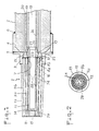
- - la figure 1 représente en coupe longitudinale un embout conforme à l'invention adapté sur l'extrémité d'une lance de gunitage traditionnelle;
- - la figure 2 est une vue de gauche du nez de l'embout de la figure 1.
- - Figure 1 shows in longitudinal section a nozzle according to the invention adapted on the end of a traditional gunning lance;
- - Figure 2 is a left view of the nose of the tip of Figure 1.
L'embout 1, assujetti à la lance de gunitage 2, comporte un barillet 3 porte-tubes maintenu sur l'extrémité frontale de la lance 2 au moyen d'une bague de maintien en acier inoxydable 4 brasée en 5 et 6 au barillet 3 et au contour cylindrique de la lance 2.The
Le barillet d'acier inoxydable 3 comporte un alésage central 7 de relativement grand diamètre et deux couronnes d'alésage 8a et 8b dans lesquels s'insèrent 35 tubes de cuivre répartis sur deux couronnes de tubes 9a et 9b de 150 m de long et 3,8 mm de diamètre intérieur fixés à une de leurs extrémités par des brasures 10.The
Les tubes 9a et 9b forment à leur autre extrémité le nez 11 de l'embout 1: ils sont contigus les uns aux autres à ce niveau, et sont enserrés entre les extrémités de deux parois sensiblement cylindriques respectivement interne 12 et externe 13.The
La paroi externe 13 en cuivre ceinture la couronne de tubes 9b et est brasée sur le barillet 3. Quoique pouvant être qualifiée de sensiblement cylindrique, elle a, dans le mode de réalisation représenté, en fait une faible conicité de l'ordre de 3% adaptée à la convergence des tubes 9. La paroi 13 peut faire saillie légèrement au-delà du nez 11 de l'embout 1.The
La paroi interne 12 a la forme d'un cylindre généralement creux, arasant le nez 11 de l'embout 1, fermé de ce côté par une paroi frontale 14 ménageant une cavité recevant un réfractaire isolant 15.The
La paroi cylindrique 12 traverse l'alésage central 7 du barillet dans lequel elle est centrée par des nervures de centrage 16. Elle comporte un épaulement 17 au voisinage du nez de la lance 2.The
La lance 2 comporte un conduit central 18 relié à une alimentation en gaz non porteur de poudre réfractaire, par exemple le comburant (ici de l'oxygène). Le conduit central 18 est séparé par une paroi annulaire 19 d'un conduit annulaire 20 relié à une alimentation en poudre réfractaire et en gaz porteur, par exemple Is gaz combustible.The
L'épaulement 17 a un contour conique 21 qui ménage avec un contour également conique 22 du barillet 3 un passage annulaire conduisant la poudre réfractoire véhiculée par son gaz porteur depuis la sortie du conduit annulsire 20 jusqu'aux entrées des tubes 9. Un joint en cuivre 23 assurs l'étanchéité entre ledit passage annulaire et l'espace interstitiel entre les tubes 9 et les parois 12 et 13.The
La paroi cylindrique 12 se prolonge vers l'intérieur du conduit 18 de la lance 2 et vient porter sur une portée 25 d'un tube d'adaptation 26 auquel elle est brasée en 27.The
Huit orifices 28 font passer l'oxygène arrivant par le conduit central 18, dans l'espace de passage interstitiel 24 duquel il débouche au niveau du nez 11 de l'embout.Eight
Une mince bague de laiton 29 (par exemple 1/2 mm d'épsisseur) peut être interposée entre les deux couronnes de tubes 9a et 9b, sur une petite longueur (15 mm par exemple).A thin brass ring 29 (for example 1/2 mm of splicer) can be interposed between the two
Le fonctionnement du dispositif est clair: en injectant dans la lance d'une part l'oxygène gazeux et d'autre part la poudre réfractaire portée par le gaz combustible, la poudre et la flamme sont fractionnées, ce qui autorise un échauffement maximal de la poudre sans mettre en jeu la température de la paroi.The operation of the device is clear: by injecting into the lance on the one hand gaseous oxygen and on the other hand the refractory powder carried by the combustible gas, the powder and the flame are fractionated, which allows maximum heating of the powder without involving the temperature of the wall.
L'embout de l'invention est donc particulièrement bien adapté à la projection de produits à haute réfractarité dont l'utilisation est nécessaire en aciérie.The tip of the invention is therefore particularly well suited to the projection of products with high refractoriness whose use is necessary in steel works.
Claims (9)
Priority Applications (1)
| Application Number | Priority Date | Filing Date | Title |
|---|---|---|---|
| AT83401750T ATE26884T1 (en) | 1982-09-13 | 1983-09-06 | NOZZLE FOR FLAME SPRAYING. |
Applications Claiming Priority (2)
| Application Number | Priority Date | Filing Date | Title |
|---|---|---|---|
| FR8215461A FR2533020A1 (en) | 1982-09-13 | 1982-09-13 | HOT TUNNEL NOZZLE |
| FR8215461 | 1982-09-13 |
Publications (2)
| Publication Number | Publication Date |
|---|---|
| EP0103515A1 EP0103515A1 (en) | 1984-03-21 |
| EP0103515B1 true EP0103515B1 (en) | 1987-04-29 |
Family
ID=9277405
Family Applications (1)
| Application Number | Title | Priority Date | Filing Date |
|---|---|---|---|
| EP83401750A Expired EP0103515B1 (en) | 1982-09-13 | 1983-09-06 | Nozzle for hot guniting |
Country Status (10)
| Country | Link |
|---|---|
| US (1) | US4562961A (en) |
| EP (1) | EP0103515B1 (en) |
| JP (1) | JPS5966368A (en) |
| AT (1) | ATE26884T1 (en) |
| AU (1) | AU564811B2 (en) |
| CA (1) | CA1200689A (en) |
| DE (1) | DE3371246D1 (en) |
| ES (1) | ES8405507A1 (en) |
| FR (1) | FR2533020A1 (en) |
| ZA (1) | ZA836319B (en) |
Families Citing this family (14)
| Publication number | Priority date | Publication date | Assignee | Title |
|---|---|---|---|---|
| GB2170122B (en) * | 1985-01-26 | 1988-11-30 | Glaverbel | Process of forming a refractory mass and lance for spraying particulate exothermically oxidisable material |
| KR960004799B1 (en) * | 1986-12-22 | 1996-04-13 | 가와사끼 세이데쓰 가부시끼가이샤 | Method and apparatus for spray coating or refractory material to refractory construction |
| US5262206A (en) * | 1988-09-20 | 1993-11-16 | Plasma Technik Ag | Method for making an abradable material by thermal spraying |
| US5019686A (en) * | 1988-09-20 | 1991-05-28 | Alloy Metals, Inc. | High-velocity flame spray apparatus and method of forming materials |
| US5206059A (en) * | 1988-09-20 | 1993-04-27 | Plasma-Technik Ag | Method of forming metal-matrix composites and composite materials |
| US5135166A (en) * | 1991-05-08 | 1992-08-04 | Plasma-Technik Ag | High-velocity thermal spray apparatus |
| US5520334A (en) * | 1993-01-21 | 1996-05-28 | White; Randall R. | Air and fuel mixing chamber for a tuneable high velocity thermal spray gun |
| US5405085A (en) * | 1993-01-21 | 1995-04-11 | White; Randall R. | Tuneable high velocity thermal spray gun |
| US5445325A (en) * | 1993-01-21 | 1995-08-29 | White; Randall R. | Tuneable high velocity thermal spray gun |
| US5486676A (en) * | 1994-11-14 | 1996-01-23 | General Electric Company | Coaxial single point powder feed nozzle |
| US5692678A (en) * | 1995-05-01 | 1997-12-02 | Kawasaki Steel Corporation | Flame spraying burner |
| US6579085B1 (en) | 2000-05-05 | 2003-06-17 | The Boc Group, Inc. | Burner and combustion method for the production of flame jet sheets in industrial furnaces |
| US7854397B2 (en) * | 2005-01-21 | 2010-12-21 | Specialty Minerals (Michigan) Inc. | Long throw shotcrete nozzle |
| CN103075887A (en) * | 2013-01-24 | 2013-05-01 | 张立生 | Supersonic speed high-temperature ceramic repair welding gun |
Family Cites Families (11)
| Publication number | Priority date | Publication date | Assignee | Title |
|---|---|---|---|---|
| US1758473A (en) * | 1924-06-30 | 1930-05-13 | Schoop Max Ulrich | Coating articles, particularly with metals |
| US1721381A (en) * | 1928-02-02 | 1929-07-16 | Gen Electric | Gas burner |
| US2544259A (en) * | 1944-11-25 | 1951-03-06 | Duccini Gaetano | Metallizing spray gun |
| US3111267A (en) * | 1957-04-18 | 1963-11-19 | Metco Inc | Apparatus for applying heat-fusible coatings on solid objects |
| NL274228A (en) * | 1961-02-01 | |||
| US3118758A (en) * | 1961-03-27 | 1964-01-21 | Union Carbide Canada Ltd | Post-mixed oxy-fuel oxide reduction |
| GB933839A (en) * | 1961-06-12 | 1963-08-14 | Pollock & Peel Ltd | Improvements in nozzles and a method of making the same |
| DE1265630B (en) * | 1962-02-08 | 1968-04-04 | Metallgesellschaft Ag | Flame spray gun, especially for oxide ceramic powders |
| US3814327A (en) * | 1971-04-06 | 1974-06-04 | Gen Electric | Nozzle for chemical reaction processes |
| LU80997A1 (en) * | 1978-03-09 | 1979-06-18 | Centre Rech Metallurgique | PROCESS FOR THE PROTECTION OF REFRACTORY WALLS OF METALLURGIC CONTAINERS |
| DE7908047U1 (en) * | 1979-02-16 | 1982-04-08 | Castolin S.A., 1025 St. Sulpice, Vaud | BURNER NOZZLE FOR FLAME SPRAYER |
-
1982
- 1982-09-13 FR FR8215461A patent/FR2533020A1/en active Granted
-
1983
- 1983-08-25 ZA ZA836319A patent/ZA836319B/en unknown
- 1983-08-25 JP JP58154249A patent/JPS5966368A/en active Pending
- 1983-08-30 AU AU18533/83A patent/AU564811B2/en not_active Ceased
- 1983-09-06 EP EP83401750A patent/EP0103515B1/en not_active Expired
- 1983-09-06 DE DE8383401750T patent/DE3371246D1/en not_active Expired
- 1983-09-06 AT AT83401750T patent/ATE26884T1/en active
- 1983-09-12 US US06/531,914 patent/US4562961A/en not_active Expired - Fee Related
- 1983-09-12 CA CA000436522A patent/CA1200689A/en not_active Expired
- 1983-09-13 ES ES525581A patent/ES8405507A1/en not_active Expired
Also Published As
| Publication number | Publication date |
|---|---|
| AU1853383A (en) | 1984-03-22 |
| AU564811B2 (en) | 1987-08-27 |
| EP0103515A1 (en) | 1984-03-21 |
| FR2533020B1 (en) | 1985-04-19 |
| ZA836319B (en) | 1984-04-25 |
| CA1200689A (en) | 1986-02-18 |
| US4562961A (en) | 1986-01-07 |
| ATE26884T1 (en) | 1987-05-15 |
| DE3371246D1 (en) | 1987-06-04 |
| FR2533020A1 (en) | 1984-03-16 |
| ES525581A0 (en) | 1984-06-01 |
| JPS5966368A (en) | 1984-04-14 |
| ES8405507A1 (en) | 1984-06-01 |
Similar Documents
| Publication | Publication Date | Title |
|---|---|---|
| EP0103515B1 (en) | Nozzle for hot guniting | |
| EP0921349B1 (en) | Fuel atomisation burner and combustion process carried out with such a burner | |
| EP0689007A1 (en) | Cooling the take-off injector in a combustion chamber with two burner heads | |
| FR2709812A1 (en) | Combustion process. | |
| FR2817016A1 (en) | Turbine cruise fuel injector assembly procedure uses metal inserts in radial wells, fused after fitting feed tubes and cylindrical tip together | |
| US5120026A (en) | Fluid cooled cutting torch for operation with a premix and postmix nozzle | |
| EP0703410B1 (en) | Oxy-fuel burner comprising a block and method for operating the same | |
| EP0646751B1 (en) | Burner and use of same in a glass furnace | |
| FR2836699A1 (en) | ROCKET MOTOR | |
| FR3021351B1 (en) | TURBOMACHINE WALL HAVING AT LEAST ONE PORTION OF COOLING ORIFICES OBSTRUCTIONS | |
| CA1110920A (en) | Method and device for sludge incineration | |
| EP0421865A1 (en) | Rocket combustion chamber | |
| CA2704800A1 (en) | Combustion method and system | |
| EP0775868A1 (en) | Gas burner for a furnacefor reheating steel industry products | |
| LU86174A1 (en) | METHOD OF FORMING A REFRACTORY MASS AND SPRAY LANCE OF REFRACTORY PARTICLES AND EXOTHERMICALLY OXIDIZABLE PARTICLES | |
| FR2549579A1 (en) | GAS BURNER FOR METALLIZATION PISTOL | |
| EP1155781A1 (en) | Thermoabrasive blast gun | |
| EP1055084B1 (en) | Method for heating products in an enclosure and burner for carrying out the method | |
| WO1998053250A1 (en) | Oxyacetylene cutting apparatus | |
| US793894A (en) | Vapor-heated or gas-heated implement. | |
| EP0406208A1 (en) | Preheating device for a molten metal casting nozzle and metal casting installation comprising such device | |
| CH247770A (en) | A method of heating an oven and an oven for carrying out this method. | |
| US2264697A (en) | Blowpipe | |
| FR2635850A1 (en) | Plasma assisted combustion device | |
| FR2604241A1 (en) | PROCESS FOR PRODUCING AN OXYGEN ENRICHED FLAME |
Legal Events
| Date | Code | Title | Description |
|---|---|---|---|
| PUAI | Public reference made under article 153(3) epc to a published international application that has entered the european phase |
Free format text: ORIGINAL CODE: 0009012 |
|
| AK | Designated contracting states |
Designated state(s): AT BE DE GB IT LU NL SE |
|
| 17P | Request for examination filed |
Effective date: 19840829 |
|
| GRAA | (expected) grant |
Free format text: ORIGINAL CODE: 0009210 |
|
| AK | Designated contracting states |
Kind code of ref document: B1 Designated state(s): AT BE DE GB IT LU NL SE |
|
| REF | Corresponds to: |
Ref document number: 26884 Country of ref document: AT Date of ref document: 19870515 Kind code of ref document: T |
|
| REF | Corresponds to: |
Ref document number: 3371246 Country of ref document: DE Date of ref document: 19870604 |
|
| ITF | It: translation for a ep patent filed | ||
| PLBE | No opposition filed within time limit |
Free format text: ORIGINAL CODE: 0009261 |
|
| STAA | Information on the status of an ep patent application or granted ep patent |
Free format text: STATUS: NO OPPOSITION FILED WITHIN TIME LIMIT |
|
| 26N | No opposition filed | ||
| PGFP | Annual fee paid to national office [announced via postgrant information from national office to epo] |
Ref country code: GB Payment date: 19910823 Year of fee payment: 9 |
|
| PGFP | Annual fee paid to national office [announced via postgrant information from national office to epo] |
Ref country code: AT Payment date: 19910829 Year of fee payment: 9 |
|
| PGFP | Annual fee paid to national office [announced via postgrant information from national office to epo] |
Ref country code: SE Payment date: 19910919 Year of fee payment: 9 |
|
| ITTA | It: last paid annual fee | ||
| PGFP | Annual fee paid to national office [announced via postgrant information from national office to epo] |
Ref country code: NL Payment date: 19910930 Year of fee payment: 9 |
|
| PGFP | Annual fee paid to national office [announced via postgrant information from national office to epo] |
Ref country code: BE Payment date: 19911003 Year of fee payment: 9 |
|
| PGFP | Annual fee paid to national office [announced via postgrant information from national office to epo] |
Ref country code: LU Payment date: 19911015 Year of fee payment: 9 |
|
| PGFP | Annual fee paid to national office [announced via postgrant information from national office to epo] |
Ref country code: DE Payment date: 19911017 Year of fee payment: 9 |
|
| EPTA | Lu: last paid annual fee | ||
| PG25 | Lapsed in a contracting state [announced via postgrant information from national office to epo] |
Ref country code: LU Free format text: LAPSE BECAUSE OF NON-PAYMENT OF DUE FEES Effective date: 19920906 Ref country code: GB Effective date: 19920906 Ref country code: AT Effective date: 19920906 |
|
| PG25 | Lapsed in a contracting state [announced via postgrant information from national office to epo] |
Ref country code: SE Effective date: 19920907 |
|
| PG25 | Lapsed in a contracting state [announced via postgrant information from national office to epo] |
Ref country code: BE Effective date: 19920930 |
|
| BERE | Be: lapsed |
Owner name: INSTITUT DE RECHERCHES DE LA SIDERURGIE FRANCAISE Effective date: 19920930 |
|
| PG25 | Lapsed in a contracting state [announced via postgrant information from national office to epo] |
Ref country code: NL Effective date: 19930401 |
|
| GBPC | Gb: european patent ceased through non-payment of renewal fee |
Effective date: 19920906 |
|
| NLV4 | Nl: lapsed or anulled due to non-payment of the annual fee | ||
| PG25 | Lapsed in a contracting state [announced via postgrant information from national office to epo] |
Ref country code: DE Effective date: 19930602 |
|
| EUG | Se: european patent has lapsed |
Ref document number: 83401750.1 Effective date: 19930406 |