EP0103480B1 - Schneideinsatzbefestigung für Fräser - Google Patents
Schneideinsatzbefestigung für Fräser Download PDFInfo
- Publication number
- EP0103480B1 EP0103480B1 EP83305324A EP83305324A EP0103480B1 EP 0103480 B1 EP0103480 B1 EP 0103480B1 EP 83305324 A EP83305324 A EP 83305324A EP 83305324 A EP83305324 A EP 83305324A EP 0103480 B1 EP0103480 B1 EP 0103480B1
- Authority
- EP
- European Patent Office
- Prior art keywords
- cutterblock
- screw
- screws
- wedge member
- head
- Prior art date
- Legal status (The legal status is an assumption and is not a legal conclusion. Google has not performed a legal analysis and makes no representation as to the accuracy of the status listed.)
- Expired
Links
Images
Classifications
-
- B—PERFORMING OPERATIONS; TRANSPORTING
- B23—MACHINE TOOLS; METAL-WORKING NOT OTHERWISE PROVIDED FOR
- B23C—MILLING
- B23C5/00—Milling-cutters
- B23C5/16—Milling-cutters characterised by physical features other than shape
- B23C5/20—Milling-cutters characterised by physical features other than shape with removable cutter bits or teeth or cutting inserts
- B23C5/22—Securing arrangements for bits or teeth or cutting inserts
- B23C5/2239—Securing arrangements for bits or teeth or cutting inserts with cutting inserts clamped by a clamping member acting almost perpendicular on the cutting face
- B23C5/2243—Securing arrangements for bits or teeth or cutting inserts with cutting inserts clamped by a clamping member acting almost perpendicular on the cutting face for plate-like cutting inserts
- B23C5/2247—Securing arrangements for bits or teeth or cutting inserts with cutting inserts clamped by a clamping member acting almost perpendicular on the cutting face for plate-like cutting inserts having a special shape
-
- B—PERFORMING OPERATIONS; TRANSPORTING
- B27—WORKING OR PRESERVING WOOD OR SIMILAR MATERIAL; NAILING OR STAPLING MACHINES IN GENERAL
- B27G—ACCESSORY MACHINES OR APPARATUS FOR WORKING WOOD OR SIMILAR MATERIALS; TOOLS FOR WORKING WOOD OR SIMILAR MATERIALS; SAFETY DEVICES FOR WOOD WORKING MACHINES OR TOOLS
- B27G13/00—Cutter blocks; Other rotary cutting tools
- B27G13/02—Cutter blocks; Other rotary cutting tools in the shape of long arbors, i.e. cylinder cutting blocks
- B27G13/04—Securing the cutters by mechanical clamping means
-
- B—PERFORMING OPERATIONS; TRANSPORTING
- B23—MACHINE TOOLS; METAL-WORKING NOT OTHERWISE PROVIDED FOR
- B23C—MILLING
- B23C2200/00—Details of milling cutting inserts
- B23C2200/16—Supporting or bottom surfaces
- B23C2200/165—Supporting or bottom surfaces with one or more grooves
Definitions
- the invention relates to rotary cutterblocks for woodworking machines, and in particular to the anchorage of the blades in such cutterblocks.
- Conventional rotary cutterblocks comprise a cylindrical cutterblock body having a number of inwardly divergent recesses in the cylindrical outer surface of the body, and a cutter blade retained in each of the recesses by a wedge member and one or more clamping screws.
- the clamping screws are dog point grub screws screw threadedly engaging a chordal threaded bore in the cutterblock to bear against a front face of the wedge member so that the cutter blade is clamped between the rear face of the wedge member and a rear face of the recess in the cutterblock body.
- the clamping screws are hexagonal headed screws screw- threadedly engaging the wedge member, with the hexagonal head of each screw projecting from the wedge member into the recess in the cutterblock body.
- Such screws are accessed and turned by means of a spanner inserted radially into the recess in the cutterblock body, between the front face of that recess and the wedge.
- One major disadvantage in such a design is that it imparts a necessary clearance between the front face of the recess and the wedge, which clearance generates substantial amounts of noise in use, particularly in high speed use, and interferes with good chip flow from the blade in use.
- a rotary cutterblock for a woodworking machine comprising a cylindrical cutterblock body having a number of inwardly divergent recesses in the cylindrical outer surface thereof and a cutter blade retained in each of the recesses by a wedge member and one or more clamping screws screw-threaded in the wedge member, characterised in that each wedge member substantially fills its recess and has its clamping screw or screws recessed therein so that a head of the or each screw lies close to the plane of the front face of the wedge member, and the cutterblock body is provided with a chordal passage for each clamping screw, aligned with the axis if the respective clamping screw for insertion of a key member to tighten or loosen the screw.
- the wedge member of the cutterblock if the invention substantially fills its recess, it may be made of a suitable profile to achieve optimum chip flow. Also such filling of the recess reduces the noise of the cutterblock in operation.
- the clamping screws of the cutterblock of the invention are headed screws (unlike the grub screws of the prior art) so that the additional material around the screwdriver slot or hexagonal shaped hole at the head of the screws provides a very considerable strengthening in an area of proved weakness. It is surprising that the cutter blocks of the invention are reliable in practice, as the chordal access passages for the clamping screws in effect remove a substantial part of the material of the cutterblock body in precisely the zone where there would otherwise have been engagement between the head of the clamping screw and the cutterblock body. This leaves the engagement of those two parts as being simply in an annular zone around the mouth of the chordal access passage, which surprisingly has been found more than adequate to provide a very safe and reliable blade anchorage.
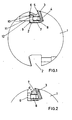
- the cutterblock comprises a cylindrical cutterblock body 1 having two diametrically opposed inwardly divergent recesses 2 formed therein.
- a blade and blade mounting In the upper of the two recesses 2 as illustrated there is shown in detail a blade and blade mounting.
- the blade 3 is shown as having a serrated back face 4, engaging mating serrations in the cutterblock body.
- the threaded shaft of the clamping screw 8 screw threadedly engages a bore in the wedge 7, and a head 9 of the screw is received in a cutaway portion 10 if the wedge 7.
- a hexongal key recess 11 In the head 9 of the screw 8 is formed a hexongal key recess 11, enabling the screw to be turned by an Allen key (not shown). To enable the key to be inserted in the recess 11, there is provided a chordal passage 12 extending through the body 1 in alignment with the axis of the screw 8.
- the screws 8 are screwed fully into the wedges 7, and the wedges inserted into the recesses 2 in the axial direction.
- Allen keys are then inserted through the passages 12 and used to withdraw successive screws 8 partially from the threaded bores in the wedges 7, until the outer annular portion of the head 9 if each screw 8 engages that portion of the front face 6 of the recess 2 immediately surrounding the passage 12. In this way the blade can be securely anchored in the cutterblock.
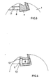
- Figure 2 shows how, in a prior design, the head 9 of each clamping screw 8 was a hexongal head that was accessed radially through a gap between the wedge 7 and the body 1 of the cutterblock.
- the spacing d between the wedge and the body did, however, produce undesirable noise during operation and interfered with good chip flow.
- Figure 3 shows an alternative prior art construction, in which the wedge 7 was retained by a dog point grub screw 8 screw threaded into the body 1 of the cutterblock.
- the relative lack of material around the hexagonal recess 11 in the grub screw 8 resulted in frequent failure of such anchorages, such failures being avoided in the cutterblock of the invention.
- Figure 4 shows another embodiment of the invention which is similar to that of Figure 1 except that the screw 8 has a head 9 which is shaped at 13 to extend partially into the chordal passage 12. This provides a more positive anchorage of the wedge 7, which may be desirable for some applications.
Landscapes
- Engineering & Computer Science (AREA)
- Mechanical Engineering (AREA)
- Life Sciences & Earth Sciences (AREA)
- Wood Science & Technology (AREA)
- Forests & Forestry (AREA)
- Milling Processes (AREA)
- Drilling Tools (AREA)
Claims (2)
Applications Claiming Priority (2)
| Application Number | Priority Date | Filing Date | Title |
|---|---|---|---|
| GB8226188 | 1982-09-11 | ||
| GB8226188 | 1982-09-11 |
Publications (3)
| Publication Number | Publication Date |
|---|---|
| EP0103480A2 EP0103480A2 (de) | 1984-03-21 |
| EP0103480A3 EP0103480A3 (en) | 1986-08-27 |
| EP0103480B1 true EP0103480B1 (de) | 1989-01-11 |
Family
ID=10532900
Family Applications (1)
| Application Number | Title | Priority Date | Filing Date |
|---|---|---|---|
| EP83305324A Expired EP0103480B1 (de) | 1982-09-11 | 1983-09-12 | Schneideinsatzbefestigung für Fräser |
Country Status (2)
| Country | Link |
|---|---|
| EP (1) | EP0103480B1 (de) |
| DE (1) | DE3378898D1 (de) |
Families Citing this family (4)
| Publication number | Priority date | Publication date | Assignee | Title |
|---|---|---|---|---|
| SE502085C2 (sv) * | 1993-04-27 | 1995-08-07 | Sandvik Ab | Fräshuvud med rilltandade kassetter |
| FI96288C (fi) * | 1995-04-20 | 1996-06-10 | Kone Wood Oy | Laite terän kiinnittämiseksi hakun pyöritettävään kiekkoon |
| SE9503867D0 (sv) * | 1995-11-02 | 1995-11-02 | Sandvik Ab | Fräsverktyg |
| DK2985100T3 (da) * | 2014-08-12 | 2020-03-02 | Lsab Sverige Ab | Skæresystem til profilfræsning |
Family Cites Families (7)
| Publication number | Priority date | Publication date | Assignee | Title |
|---|---|---|---|---|
| FR610027A (fr) * | 1925-06-06 | 1926-08-28 | Const Mecaniques De Vendeuvre | Dispositif de serrage des lames de machines-outils rotatives à grande vitesse |
| GB550077A (en) * | 1941-07-04 | 1942-12-22 | C D Monninger Ltd | Improvements in or relating to rotary cutter heads for wood-working and like machines |
| CH241723A (de) * | 1941-10-01 | 1946-03-31 | Maurer Sprissler Luise | Umlaufender Messerkopf für Holzbearbeitungsmaschinen. |
| DE839556C (de) * | 1950-06-29 | 1952-05-23 | Boettcher & Gessner | Hobelmesserwelle fuer Holzbearbeitung mit Keileinspannung |
| DE858602C (de) * | 1951-07-05 | 1952-12-08 | Heinrich Gensheimer & Soehne M | Sicherheitsmesserwelle |
| DE1046862B (de) * | 1952-12-31 | 1958-12-18 | Jakob Schmid Werkzeugfabrik | Messereinstellung an Messerwellen bzw. Messerkoepfen |
| DE2226245C3 (de) * | 1972-05-30 | 1979-11-29 | Alfred 5620 Velbert Wormsbaecher | Messerkopf für Holz- und Kunststoffbearbeitung |
-
1983
- 1983-09-12 EP EP83305324A patent/EP0103480B1/de not_active Expired
- 1983-09-12 DE DE8383305324T patent/DE3378898D1/de not_active Expired
Also Published As
| Publication number | Publication date |
|---|---|
| DE3378898D1 (en) | 1989-02-16 |
| EP0103480A2 (de) | 1984-03-21 |
| EP0103480A3 (en) | 1986-08-27 |
Similar Documents
| Publication | Publication Date | Title |
|---|---|---|
| US7311480B2 (en) | Plate-shaped cutter insert for direct clamping attachment in a base body | |
| FI71808C (fi) | Graevtand. | |
| US4728215A (en) | Corner connection for furniture | |
| US6520055B1 (en) | Screwdriver or screwdriver attachment | |
| EP1325787A1 (de) | Werkzeug und Werkzeugkörper für Schneidbearbeitung | |
| US4519731A (en) | Milling cutter | |
| US6551036B2 (en) | Drilling bit and holder for drilling bit | |
| US5749689A (en) | Drill, particulary drilling screw | |
| CN101405103A (zh) | 钻孔工具以及用于钻孔工具的工具头 | |
| US6290436B1 (en) | Cutting insert for rotating cutting tools | |
| US11045971B2 (en) | Cutter head and cutter head system | |
| US5857506A (en) | Replaceable insert cutting tools | |
| KR20010012706A (ko) | 스크류를 지지하고 체결하기 위한 신규 시스템 | |
| CA2516845A1 (en) | Osteosynthesis plate | |
| US8899597B2 (en) | Clamping system | |
| EP0103480B1 (de) | Schneideinsatzbefestigung für Fräser | |
| US11540456B2 (en) | Tree stump grinder | |
| JP2006068898A (ja) | フライス工具、特にねじフライス | |
| EP1283082B1 (de) | Drehendes Schneidwerkzeug | |
| US8690491B2 (en) | Rotary cutting tool | |
| US4564993A (en) | Double nut and method of forming the double nut | |
| US3039508A (en) | Wedge locked insert | |
| SU1808509A1 (ru) | Сборное комбинированное сверло | |
| GB2087792A (en) | Profiling discs for woodworking machinery | |
| CA1320825C (en) | Device for locking a tool holder to a tool block |
Legal Events
| Date | Code | Title | Description |
|---|---|---|---|
| PUAI | Public reference made under article 153(3) epc to a published international application that has entered the european phase |
Free format text: ORIGINAL CODE: 0009012 |
|
| AK | Designated contracting states |
Designated state(s): CH DE FR GB IT LI NL SE |
|
| PUAL | Search report despatched |
Free format text: ORIGINAL CODE: 0009013 |
|
| AK | Designated contracting states |
Kind code of ref document: A3 Designated state(s): CH DE FR GB IT LI NL SE |
|
| 17P | Request for examination filed |
Effective date: 19870406 |
|
| 17Q | First examination report despatched |
Effective date: 19880609 |
|
| GRAA | (expected) grant |
Free format text: ORIGINAL CODE: 0009210 |
|
| STAA | Information on the status of an ep patent application or granted ep patent |
Free format text: STATUS: THE PATENT HAS BEEN GRANTED |
|
| AK | Designated contracting states |
Kind code of ref document: B1 Designated state(s): CH DE FR GB IT LI NL SE |
|
| ITF | It: translation for a ep patent filed | ||
| REF | Corresponds to: |
Ref document number: 3378898 Country of ref document: DE Date of ref document: 19890216 |
|
| ET | Fr: translation filed | ||
| PLBI | Opposition filed |
Free format text: ORIGINAL CODE: 0009260 |
|
| 26 | Opposition filed |
Opponent name: JAKOB SCHMID GMBH + CO. Effective date: 19890724 |
|
| NLR1 | Nl: opposition has been filed with the epo |
Opponent name: JACOB SCHMID GMBH |
|
| PLBG | Opposition deemed not to have been filed |
Free format text: ORIGINAL CODE: 0009274 |
|
| 26D | Opposition deemed not to have been filed | ||
| NLXE | Nl: other communications concerning ep-patents (part 3 heading xe) |
Free format text: IN PAT.BUL.22/89:THE OPPOSITION SHOULD BE DEEMED NOT TO HAVE BEEN FILED |
|
| ITTA | It: last paid annual fee | ||
| PGFP | Annual fee paid to national office [announced via postgrant information from national office to epo] |
Ref country code: SE Payment date: 19920825 Year of fee payment: 10 |
|
| PGFP | Annual fee paid to national office [announced via postgrant information from national office to epo] |
Ref country code: FR Payment date: 19920828 Year of fee payment: 10 |
|
| PGFP | Annual fee paid to national office [announced via postgrant information from national office to epo] |
Ref country code: GB Payment date: 19920901 Year of fee payment: 10 Ref country code: DE Payment date: 19920901 Year of fee payment: 10 |
|
| PGFP | Annual fee paid to national office [announced via postgrant information from national office to epo] |
Ref country code: NL Payment date: 19920930 Year of fee payment: 10 |
|
| PGFP | Annual fee paid to national office [announced via postgrant information from national office to epo] |
Ref country code: CH Payment date: 19921125 Year of fee payment: 10 |
|
| PG25 | Lapsed in a contracting state [announced via postgrant information from national office to epo] |
Ref country code: GB Effective date: 19930912 |
|
| PG25 | Lapsed in a contracting state [announced via postgrant information from national office to epo] |
Ref country code: SE Effective date: 19930913 |
|
| PG25 | Lapsed in a contracting state [announced via postgrant information from national office to epo] |
Ref country code: LI Effective date: 19930930 Ref country code: CH Effective date: 19930930 |
|
| PG25 | Lapsed in a contracting state [announced via postgrant information from national office to epo] |
Ref country code: NL Effective date: 19940401 |
|
| GBPC | Gb: european patent ceased through non-payment of renewal fee |
Effective date: 19930912 |
|
| NLV4 | Nl: lapsed or anulled due to non-payment of the annual fee | ||
| PG25 | Lapsed in a contracting state [announced via postgrant information from national office to epo] |
Ref country code: FR Free format text: LAPSE BECAUSE OF NON-PAYMENT OF DUE FEES Effective date: 19940531 |
|
| REG | Reference to a national code |
Ref country code: CH Ref legal event code: PL |
|
| PG25 | Lapsed in a contracting state [announced via postgrant information from national office to epo] |
Ref country code: DE Effective date: 19940601 |
|
| REG | Reference to a national code |
Ref country code: FR Ref legal event code: ST |
|
| EUG | Se: european patent has lapsed |
Ref document number: 83305324.2 Effective date: 19940410 |
|
| RIN2 | Information on inventor provided after grant (corrected) |
Inventor name: STOCKER, MARK ANDREW |