EP0103414A2 - Eléments de jonction pour conduit électrique - Google Patents
Eléments de jonction pour conduit électrique Download PDFInfo
- Publication number
- EP0103414A2 EP0103414A2 EP83304684A EP83304684A EP0103414A2 EP 0103414 A2 EP0103414 A2 EP 0103414A2 EP 83304684 A EP83304684 A EP 83304684A EP 83304684 A EP83304684 A EP 83304684A EP 0103414 A2 EP0103414 A2 EP 0103414A2
- Authority
- EP
- European Patent Office
- Prior art keywords
- sockets
- junction piece
- cover
- piece
- connecting portion
- Prior art date
- Legal status (The legal status is an assumption and is not a legal conclusion. Google has not performed a legal analysis and makes no representation as to the accuracy of the status listed.)
- Withdrawn
Links
Images


Classifications
-
- H—ELECTRICITY
- H02—GENERATION; CONVERSION OR DISTRIBUTION OF ELECTRIC POWER
- H02G—INSTALLATION OF ELECTRIC CABLES OR LINES, OR OF COMBINED OPTICAL AND ELECTRIC CABLES OR LINES
- H02G3/00—Installations of electric cables or lines or protective tubing therefor in or on buildings, equivalent structures or vehicles
- H02G3/02—Details
- H02G3/06—Joints for connecting lengths of protective tubing or channels, to each other or to casings, e.g. to distribution boxes; Ensuring electrical continuity in the joint
Definitions
- This invention relates to conduits for electrical cable.
- it relates to junction pieces for joining ends of conduits, e.g. at corners, and having removable covers to enable ease of fitting and inspection of the electric cables contained in the conduit.
- junction pieces are constructed as "elbows", "small bends” (having a larger bend radius than an “elbow”), and "T” junctions, and were originally made of cast iron.
- a flat, plate-like lid portion was provided, which was fitted over an opening in the main portion by means of screws.
- junction pieces have been made.of plastics material, using similar screwed inspection plates. To fit or inspect the cables, therefore, (and therefore costly) unscrewing of the plates is involved.
- the inclusion of metallic screws can add an undesirable electric conducting path through the material of the fitting.
- the inspection plates could therefore be inadequately secured.for a period of time until replacement screws were fixed. Replacement screws might well not be of the correct size, resulting in deterioration of the thread. The whole junction piece would eventually have to be replaced much earlier than would otherwise be necessary due to inadequate securement and permanent damage to the inspection cover.
- This present invention is aimed at overcoming these disadvantages.
- junction piece for cable conduits comprising A a base portion including
- the cover may comprise side wall portions which engage over side wall portions of the connecting portion. These side wall portions may have generally parallel outer surfaces. A part of the connecting portion immediately adjacent the sockets may extend around an upper part of each socket as a recessed shoulder so that at least part of the exterior surface of the cover (when fitted) lies substantially flush with part of the exterior surface of the sockets.
- the seating plane may be defined by the bottom surface of the side walls and end walls of the connecting portion or by one or more projections from a bottom wall of the channel part of the connecting portion. In one embodiment.the seating plane is defined by the bottom surface of a limb which projects from a bottom wall of the channel part of the connecting portion.
- the junction piece of the invention is made from a mouldable plastics material, and in particular from PVC.
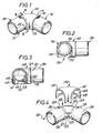
- Figures 1 to 4 show at 110 a junction piece in the form of an elbow comprising a base portion 100 ( Figure 4) which comprises two sockets 130 connected at right angles one to the other by a central connecting portion 120 which provides with a cover 140 a generally cylindrical duct aligned with, and of substantially the same cross- sectional area and shape as, the interior of the sockets 130.
- the sockets 130 have generally cylindrical inner and outer surfaces. To provide a friction fit with the conduit sections which they are designed to receive, the inner surfaces of the sockets are provided with friction fitting means which comprise a slight inward taper of the sockets and "flats" or shallow ribs which taper with the general socket taper.
- the conduit sections are preferably held in place with adhesive, e.g. a solvent weld adhesive.
- a stop means in the form of a radially extending internal shoulder 132 is provided in the internal : surfaces of the sockets 130 near their inner ends.
- the central connecting portion 120 comprisessa channel part-121 of semicircular cross-section which extends through the right angle.
- Side walls 122 extend from the upper edges of the channel part 121 to define with end walls 125 a planar seating surface at their surfaces remote from the channel opening.
- the outer surfaces of the end walls 125 extend from the axially outer extremeties of the shoulders 124, as shown in Figure 4, and the parallel outer surfaces of the side walls 122 provide engagement surfaces for the cover 140.
- the cover 140 also extends through a right angle to fit over the central connecting portion 120. It comprises side walls 142 which engage over the side walls 122 of the central connecting portion 120 to a position short of the seating plane surface defined by the bottom surfaces of the walls 122, 125.
- the cover 140 is adapted to be engaged with the base portion 100 by snap engagement. This is enabled by projecting ridges 123 extending along portions of the outer surfaces of the side walls 122 which engage in grooves 143 in the inner surfaces of the walls 142 of the cover 140.
- recesses 131 having a sloping floor, are provided at the top of the sockets, leading to the shoulder 124, to allow access for a lever such as a screwdriver.
- Complementary recesses 141 are provided in the upper inner surfaces of the cover 140.
- the curved interior surfaces of the cover 140 and the channel part 121 provide a generally circular sectioned passageway continuing on a common axis from one socket to the other.
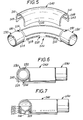
- Figures 5 to 8 show a junction piece in the form of a small bend. This embodiment is very similar to the first embodiment with two sockets being substantially at right angles to each other; the radius of bend is much larger, however. Equivalent features to those in the first embodiment shown in Figures 1 to 4 are identified by the same-last two digits prefixed by 2 instead of 1.
- the seating plane of the latter embodiment is defined by the bottom surface of a limb 226 which extends along the length of the central connecting portion 220 ( Figure 6) from the convex bottom surface of the channel part 221 and beyond the bottom surfaces of the side walls 222 and end walls 225 of the central connecting portion which are thereby raised from the wall surface against which the conduits are seated.
- the third embodiment shown in Figures 8 to 12, is a "T" junction piece, and features similar to those in the first two embodiments are prefixed by the numeral 3 instead of 1 or 2.
- the channel part 321 of the central connecting portion 320 can be considered to include a straight cross piece 321a and a straight stem piece 321b which joins the cross piece 321a substantially in the middle of the cross piece.
- Sockets 330 are disposed at each end of the channel pieces of the central connecting portion.
- the channel pieces interconnect to provide a duct between any-two sockets.
- the portion 340a of the cover 340 corresponding to the cross piece 321a is of 'U' shape-cross section, and the portion 340b corresponding to the stem portion 321b is similarly 'U' shaped, joining the cross piece portion of the cover 321a substantially in the middle. When in place, therefore, the cover 340 provides with the base portion 300 a passageway of substantially circular cross-section between any two sockets.
- the seating plane is defined in this embodiment by the bottom surfaces 326 of the side walls 322 and the bottom surfaces 327 of the of the end walls 325 of the central connecting portion 320.
- the ridges 323 of thcsnap engagement means between the cover 340 and base portion 300 are disposed along the outer surfaces of the side walls 322 of the channel part 321, and the corresponding grooves 343 are disposed along the inner surfaces of the cover 340.
- Recesses 331 are also provided in the top outer surface of the sockets 330 with complementary recesses 341 in the upper inner surface of the cover 340 adjacent the recesses 331, to permit access of a lever between the cover 340 and base portion 300.
- junction pieces of traditional form have been described, such as "elbow”, “small bend”.and “T”, other forms of junction pieces could be made within the scope of the invention.
Landscapes
- Engineering & Computer Science (AREA)
- Architecture (AREA)
- Civil Engineering (AREA)
- Structural Engineering (AREA)
- Details Of Indoor Wiring (AREA)
Applications Claiming Priority (2)
| Application Number | Priority Date | Filing Date | Title |
|---|---|---|---|
| GB8223376 | 1982-08-13 | ||
| GB08223376A GB2126018B (en) | 1982-08-13 | 1982-08-13 | Junction pieces for electric conduit |
Publications (2)
| Publication Number | Publication Date |
|---|---|
| EP0103414A2 true EP0103414A2 (fr) | 1984-03-21 |
| EP0103414A3 EP0103414A3 (fr) | 1985-05-29 |
Family
ID=10532294
Family Applications (1)
| Application Number | Title | Priority Date | Filing Date |
|---|---|---|---|
| EP83304684A Withdrawn EP0103414A3 (fr) | 1982-08-13 | 1983-08-12 | Eléments de jonction pour conduit électrique |
Country Status (2)
| Country | Link |
|---|---|
| EP (1) | EP0103414A3 (fr) |
| GB (1) | GB2126018B (fr) |
Cited By (2)
| Publication number | Priority date | Publication date | Assignee | Title |
|---|---|---|---|---|
| AU775235B2 (en) * | 1999-10-15 | 2004-07-22 | Legrand | Accessory adapted to be attached to a base section of trunking for routing electrical cables |
| US9948078B2 (en) | 2015-03-06 | 2018-04-17 | Alpin Management Partners Ltd. | Electrical conduit body with wiring chamber |
Families Citing this family (1)
| Publication number | Priority date | Publication date | Assignee | Title |
|---|---|---|---|---|
| DE102020133405A1 (de) * | 2020-12-14 | 2022-06-15 | Ambu A/S | Endoskop mit Konnektor |
Family Cites Families (10)
| Publication number | Priority date | Publication date | Assignee | Title |
|---|---|---|---|---|
| DE552993C (de) * | 1930-03-25 | 1932-06-20 | Carl Vitte Sen | Vorrichtung zur Verbindung von Rohren an Abzweig- und Kniestellen von Installationsroehrensystemen |
| GB402555A (en) * | 1931-09-01 | 1933-12-07 | Jeumont Forges Const Elec | Metallic casing for electrical wiring |
| GB606911A (en) * | 1946-12-04 | 1948-08-23 | Crittall R & Co Ltd | Improvements in or relating to electric conduit and cable junction boxes |
| FR1023028A (fr) * | 1950-08-04 | 1953-03-12 | Raccord tubulaire pour conduite électrique | |
| FR2050611A5 (fr) * | 1969-06-18 | 1971-04-02 | Goyer Prosper | |
| US3711633A (en) * | 1971-12-02 | 1973-01-16 | Gen Motors Corp | Fitting means for axially slit corrugated conduits |
| GB1493410A (en) * | 1976-09-15 | 1977-11-30 | Marshall Ltd C & C | Trunking connectors |
| GB1581132A (en) * | 1977-07-04 | 1980-12-10 | Ross W B | Insulator assemblies for pipe bends |
| GB1589475A (en) * | 1977-11-22 | 1981-05-13 | Costello H J | Sheathing material for insulating a pipe or pipe fitting |
| DE2828893C2 (de) * | 1978-06-30 | 1984-08-16 | Josef Schlemmer GmbH, 8011 Poing | Rohrverbinder für Kabelschutzrohre |
-
1982
- 1982-08-13 GB GB08223376A patent/GB2126018B/en not_active Expired
-
1983
- 1983-08-12 EP EP83304684A patent/EP0103414A3/fr not_active Withdrawn
Cited By (2)
| Publication number | Priority date | Publication date | Assignee | Title |
|---|---|---|---|---|
| AU775235B2 (en) * | 1999-10-15 | 2004-07-22 | Legrand | Accessory adapted to be attached to a base section of trunking for routing electrical cables |
| US9948078B2 (en) | 2015-03-06 | 2018-04-17 | Alpin Management Partners Ltd. | Electrical conduit body with wiring chamber |
Also Published As
| Publication number | Publication date |
|---|---|
| GB2126018A (en) | 1984-03-14 |
| EP0103414A3 (fr) | 1985-05-29 |
| GB2126018B (en) | 1985-10-02 |
Similar Documents
| Publication | Publication Date | Title |
|---|---|---|
| US4355198A (en) | Screw retaining and aligning cover plate | |
| US4391426A (en) | Support strip with U-shaped cross-section of plastic material for supporting conduits, cables and the like | |
| US4138185A (en) | Electric cord clamp device | |
| US4494779A (en) | Connector fitting for electrical box | |
| CA2260538A1 (fr) | Clip a ressort d'ensemble de connecteur de conduits avec extremite de retenue de conduit en eventail | |
| CA2174393C (fr) | Appliques morales a emboitement pour installations electriques jumelees | |
| US20070045004A1 (en) | Electrical connector having an outlet end angularly disposed relative an inlet end with outer retainer ring about the outlet end and internal unidirectional conductor retainer in the inlet end | |
| CA2008296A1 (fr) | Accessoire pour l'interconnexion de canalisations non metalliques | |
| CA2260535A1 (fr) | Ensemble de connecteur de conduits avec dispositif angule de retenue de conduit | |
| US5484309A (en) | Electrical receptacle assembly with interference fitting and latching parts | |
| US4426754A (en) | Clamp for multiple electrical cables | |
| US4845312A (en) | Electrical outlet box and outlet therefor | |
| US4465393A (en) | Plastic ball socket extruded in one piece for a ball-and-socket joint | |
| US4575132A (en) | Conduit connector wedge type | |
| EP0103414A2 (fr) | Eléments de jonction pour conduit électrique | |
| US6680438B1 (en) | Decorative electrical outlet and switch plate cover | |
| US3467768A (en) | Connector block boot | |
| US12327985B2 (en) | Adjustable width power distribution block | |
| US4782613A (en) | Identification seal for electricial cable | |
| US3112938A (en) | Integral cable clamp construction for electrical connection box | |
| US4920722A (en) | Composable well | |
| US4006958A (en) | Right angle electrical plug | |
| CN112714987B (zh) | 电气箱线缆连接器 | |
| US20160380418A1 (en) | Device for receiving a cable harness | |
| GB2115601A (en) | Battery case and receptacle |
Legal Events
| Date | Code | Title | Description |
|---|---|---|---|
| PUAI | Public reference made under article 153(3) epc to a published international application that has entered the european phase |
Free format text: ORIGINAL CODE: 0009012 |
|
| AK | Designated contracting states |
Designated state(s): AT BE CH DE FR GB IT LI LU NL SE |
|
| PUAL | Search report despatched |
Free format text: ORIGINAL CODE: 0009013 |
|
| AK | Designated contracting states |
Designated state(s): AT BE CH DE FR GB IT LI LU NL SE |
|
| STAA | Information on the status of an ep patent application or granted ep patent |
Free format text: STATUS: THE APPLICATION IS DEEMED TO BE WITHDRAWN |
|
| 18D | Application deemed to be withdrawn |
Effective date: 19860130 |
|
| RIN1 | Information on inventor provided before grant (corrected) |
Inventor name: CHEETHAM, COLIN R. |