EP0102339A2 - Anti-theft device - Google Patents
Anti-theft device Download PDFInfo
- Publication number
- EP0102339A2 EP0102339A2 EP83870062A EP83870062A EP0102339A2 EP 0102339 A2 EP0102339 A2 EP 0102339A2 EP 83870062 A EP83870062 A EP 83870062A EP 83870062 A EP83870062 A EP 83870062A EP 0102339 A2 EP0102339 A2 EP 0102339A2
- Authority
- EP
- European Patent Office
- Prior art keywords
- vehicle
- stand
- axis
- theft device
- ground
- Prior art date
- Legal status (The legal status is an assumption and is not a legal conclusion. Google has not performed a legal analysis and makes no representation as to the accuracy of the status listed.)
- Withdrawn
Links
Images


Classifications
-
- B—PERFORMING OPERATIONS; TRANSPORTING
- B60—VEHICLES IN GENERAL
- B60R—VEHICLES, VEHICLE FITTINGS, OR VEHICLE PARTS, NOT OTHERWISE PROVIDED FOR
- B60R25/00—Fittings or systems for preventing or indicating unauthorised use or theft of vehicles
- B60R25/001—Anti-theft devices acting on jacking means or props, e.g. for trailers
-
- B—PERFORMING OPERATIONS; TRANSPORTING
- B60—VEHICLES IN GENERAL
- B60R—VEHICLES, VEHICLE FITTINGS, OR VEHICLE PARTS, NOT OTHERWISE PROVIDED FOR
- B60R25/00—Fittings or systems for preventing or indicating unauthorised use or theft of vehicles
Landscapes
- Engineering & Computer Science (AREA)
- Mechanical Engineering (AREA)
- Transportation (AREA)
- Automatic Cycles, And Cycles In General (AREA)
- Lock And Its Accessories (AREA)
Abstract
Description
La présente invention a pour objet un dispositif antivol pour engin roulant et en particulier un dispositif antivol pour véhicule automobile.The subject of the present invention is an anti-theft device for a rolling vehicle and in particular an anti-theft device for a motor vehicle.
On connaît divers systèmes antivol, prévus pour des véhicules automobiles, qui se subdivisent en deux catégories principales ; les dispositifs à clef permettant soit la mise hors circuit des moyens électriques permettant le démarrage du moteur du véhicule, soit le blocage de la direction de ce dernier ou encore une combinaison mise hors circuit desdits moyens et blocage de direction et des dispositifs d'alarme sonore qui se déclenchent lorsque l'on touche à certains organes du véhicule ou lorsque l'on s'introduit dans ce dernier.Various anti-theft systems are known, intended for motor vehicles, which are subdivided into two main categories; key devices allowing either the deactivation of the electrical means allowing the starting of the vehicle engine, or the blocking of the direction of the latter or a combination of the said means and the direction blocking and the audible alarm devices which are triggered when you touch certain parts of the vehicle or when you enter it.
Ces dispositifs connus présentent chacun des inconvénients. En effet, on sait, qu'il est aisé soit de déconnecter les fils aboutissant à l'interrupteur à clef permettant la mise hors circuit des moyens électriques susdits et d'établir un contact entre les fils qui permettent le démarrage du moteur et assurent son fonctionnement, soit de rendre cet interrupteur à clef inopérant en effectuant un branchement sur l'installation électrique du véhicule tel qu'il permette la mise en marche du moteur. On sait aussi qu'il suffit d'exercer un effort violent sur le volant d'un véhicule pour mettre hors d'état des dispositifs à clef assurant le blocage de la direction.These known devices each have drawbacks. Indeed, we know that it is easy either to disconnect the wires leading to the key switch allowing the above-mentioned electrical means to be switched off and to establish contact between the wires which allow the engine to start and ensure its operation, or to make this key switch inoperative by making a connection to the vehicle's electrical installation such that it allows the engine to start. We also know that it suffices to exert a violent force on the steering wheel of a vehicle to disable key devices ensuring the steering lock.
En ce qui concerne les dispositifs d'alarme sonore, si ceux-ci peuvent dissuader les voleurs, ils ne peuvent s'opposer à la mise en marche et au déplacement du véhicule jusqu'à un endroit isolé ou ledit dispositif d'alarme serait déconnecté. De plus, ces dispositifs présentent l'inconvénient de provoquer de fausses alarmes dues à des vibrations ou à de légers chocs.Regarding alarm devices audible, if these can dissuade thieves, they cannot oppose the starting and moving of the vehicle to an isolated place where said alarm device would be disconnected. In addition, these devices have the disadvantage of causing false alarms due to vibrations or slight shocks.
Pour interdire le déplacement d'un véhicule, on connaît également une pince appelée "sabot de Denver" ou "sabot" et utilisé notamment par la police française pour bloquer une roue d'un véhicule en stationnement illicite. Cette pince ne peut pas être utilement employée comme dispositif antivol du fait que la mise en marche du véhicule par son propriétaire distrait ou par un voleur ignorant la présence de la pince pourrait occasionner des dégâts importants au véhicule.To prohibit the movement of a vehicle, there is also known pliers called "Denver shoe" or "shoe" and used in particular by French police to block a wheel of a vehicle in illegal parking. This clamp cannot be usefully used as an anti-theft device since the starting of the vehicle by its distracted owner or by a thief ignoring the presence of the clamp could cause significant damage to the vehicle.
L'invention a pour but de remédier à ces inconvénients et de procurer un dispositif antivol empêchant de manière fiable le déplacement d'un véhicule sans causer de dommage à ce dernier, même en cas de fausse manoeuvre du dispositif par un conducteur autorisé du véhicule.The invention aims to remedy these drawbacks and to provide an anti-theft device reliably preventing the movement of a vehicle without causing damage to the latter, even in the event of a false operation of the device by an authorized driver of the vehicle.
A cet effet, suivant l'invention, le dispositif antivol comprend des moyens associés au véhicule et agencés pour occuper au moins deux positions, une position inactive dans laquelle ils sont situés à l'écart du sol lorsque le véhicule va normalement être mis en mouvement ainsi que lorsqu'il est en mouvement et une position active dans laquelle il prend appui sur le sol et provoque le soulèvement du véhicule de manière à ce que le pneumatique d'au moins une des roues motrices n'ait plus une adhérence au sol suffisante pour que ledit véhicule puisse se déplacer sous l'action de son moteur, des moyens verrouillables inviolables étant prévus pour déplacer les moyens précités de leur position inactive à leur position active et vice versa ainsi que pour les maintenir dans la position choisie.To this end, according to the invention, the anti-theft device comprises means associated with the vehicle and arranged to occupy at least two positions, an inactive position in which they are located away from the ground when the vehicle will normally be set in motion. as well as when it is in motion and an active position in which it rests on the ground and causes the vehicle to be lifted so that the tire of at least one of the drive wheels no longer has sufficient grip on the ground so that said vehicle can move under the action of its engine, tamper-evident lockable means being provided for moving the aforementioned means from their inactive position to their active position and vice versa as well as for maintaining them in the chosen position.
Suivant une forme de réalisation de l'invention, les moyens associés au véhicule et prévus pour occuper les deux positions susdites sont agencés pour occuper une troisième position intermédiaire dans laquelle ils posent sur le sol lorsque le véhicule est en stationnement et que l'on désire le protéger contre le vol, ces moyens étant en outre agencés pour qu'ils passent automatiquement de cette position intermédiaire à la position active susdite lors d'un déplacement frauduleux du véhicule.According to one embodiment of the invention, the means associated with the vehicle and provided for occupying the two aforementioned positions are arranged to occupy a third intermediate position in which they lay on the ground when the vehicle is parked and that it is desired protect it against theft, these means being further arranged so that they automatically pass from this intermediate position to the above active position during fraudulent movement of the vehicle.
Suivant un mode de réalisation avantageux de l'invention, les moyens associés au véhicule et agencés pour occuper les positions susdites comprennent au moins une béquille s'étendant sensiblement parallèlement au plan vertical passant par l'axe longitudinal du véhicule, une des extrémités de cette béquille étant calée sur un arbre pouvant tourner autour d'un axe, fixe par rapport au véhicule, sensiblement horizontal et perpendiculaire audit plan vertical, l'autre extrémité de la béquille étant libre et dirigée vers l'avant du véhicule, la distance séparant l'axe de l'arbre susdit de l'extrémité libre de la béquille étant supérieure à la distance séparant cet axe du sol lorsque le véhicule occupe une position telle qu'au moins une de ses roues motrices soit n'offre pratiquement plus d'adhérence avec le sol, soit n'est plus en contact avec le sol, l'arbre sur lequel est monté la béquille étant supporté, de manière à pouvoir tourner autour de son axe, dans un boîtier fixé au châssis ou au plancher du véhicule, les moyens verrouillables précités prévus pour déplacer la béquille, entre sa position inactive dans laquelle elle est sensiblement parallèle, au sol et sa position intermédiaire dans laquelle elle pose obliquement sur le sol et vice versa, étant agencés dans ce boîtier.According to an advantageous embodiment of the invention, the means associated with the vehicle and arranged to occupy the abovementioned positions comprise at least one stand extending substantially parallel to the vertical plane passing through the longitudinal axis of the vehicle, one of the ends of this stand being propped on a shaft which can rotate about an axis, fixed relative to the vehicle, substantially horizontal and perpendicular to said vertical plane, the other end of the stand being free and directed towards the front of the vehicle, the distance separating l axis of the aforementioned shaft of the free end of the stand being greater than the distance separating this axis from the ground when the vehicle occupies a position such that at least one of its drive wheels is practically offers no more grip with the ground, or is no longer in contact with the ground, the shaft on which the stand is mounted being supported, so as to be able to rotate about its axis, in a housing fixed to the chassis or to the vehicle floor, the aforementioned locking means provided for moving the stand, between its inactive position in which it is substantially parallel to the ground and its intermediate position in which it rests obliquely on the ground and vice versa, being arranged in this housing.
Suivant une forme de réalisation particulièrement avantageuse de l'invention, les moyens susdits prévus pour déplacer la béquille comprennent une vis sans fin supportée dans le boîtier précité pour que son axe soit situé dans un plan perpendiculaire à l'axe de l'arbre sur lequel est montée la béquille, des moyens, tels que moteur électrique agencés pour faire tourner la vis sans fin, autour de son axe, dans un sens et dans l'autre, un élément taraudé agencé sur la vis sans fin de manière à ce qu'il puisse se déplacer suivant l'axe de cette dernière lorsque celle-ci est entraînée en rotation, des moyens coopérant avec l'élément taraudé pour interdire sa rotation autour de l'axe de la vis sans fin et une bielle reliant la béquille à l'élément taraudé et agencé de manière à ce que, d'une part, le déplacement de l'élément taraudé sur la vis sans fin provoque le pivotement de la béquille autour de l'axe de l'arbre sur lequel elle est montée et d'autre part, que le déplacement de la béquille de sa position intermédiaire à sa position active précitée, dans laquelle elle provoque le soulèvement du véhicule, puisse s'effectuer sans que la bielle exerce une poussée sur l'élément taraudé.According to a particularly advantageous embodiment of the invention, the aforementioned means provided for moving the stand include a worm screw supported in the aforementioned housing so that its axis is located in a plane perpendicular to the axis of the shaft on which is mounted the stand, means, such as an electric motor arranged to rotate the worm, about its axis, in one direction and in the other, a threaded element arranged on the worm so that it can move along the axis of the latter when the latter is rotated, means cooperating with the threaded element to prevent its rotation about the axis of the worm and a connecting rod connecting the stand to the '' tapped element and arranged in such a way that, on the one hand, the displacement of the tapped element on the worm screw causes the crutch to pivot about the axis of the shaft on which it is mounted and d on the other hand, that moving the crutch from its intermediate position to its aforementioned active position, in which it causes the lifting of the vehicle, can be carried out without the rod exerting a thrust on the threaded element.
D'autres détails et particularités de l'invention, ressortiront de la description des dessins annexés au présent mémoire et qui représentent, à titre d'exemples non limitatifs, des formes de réalisation particulières du dispositif antivol suivant l'invention.Other details and particularities of the invention will emerge from the description of the drawings appended to this specification and which represent, by way of non-limiting examples, particular embodiments of the anti-theft device according to the invention.
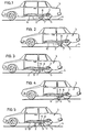
Les figures 1 et 2 sont des vues en élévation schématiques montrant un véhicule automobile équipé du dispositif antivol suivant l'invention, la figure 1 montrant le dispositif en position inactive, tandis que la figure 2 montre le dispositif en position active dans laquelle une des roues motrices du véhicule n'a plus d'adhérence au sol.Figures 1 and 2 are elevational views schematics showing a motor vehicle equipped with the anti-theft device according to the invention, FIG. 1 showing the device in the inactive position, while FIG. 2 shows the device in the active position in which one of the drive wheels of the vehicle no longer has grip on the ground.
Les figures 3 à 5 sont des vues en élévation schématiques montrant un véhicule automobile équipé d'une variante du dispositif illustré aux figures 1 et 2, la figure 3 montrant le dispositif en position inactive, la figure 4 montrant le dispositif occupant sa position intermédiaire susdite dans laquelle les moyens précités posent sur le sol, tandis que la figure 5 montre le dispositif en position active dans laquelle il soulève le véhicule lors de sa mise en marche frauduleuse.Figures 3 to 5 are schematic elevational views showing a motor vehicle equipped with a variant of the device illustrated in Figures 1 and 2, Figure 3 showing the device in the inactive position, Figure 4 showing the device occupying its above intermediate position in which the aforementioned means are placed on the ground, while FIG. 5 shows the device in the active position in which it lifts the vehicle when it is fraudulently started.
La figure 6 est une vue en élévation et en coupe montrant, à plus grande échelle, le dispositif antivol illustré aux figures 3 à 5.FIG. 6 is a view in elevation and in section showing, on a larger scale, the anti-theft device illustrated in FIGS. 3 to 5.
La figure 7 est une vue en plan correspondant à la figure 6. La figure 8 est une vue en coupe suivant la ligne VIII-VIII de la figure 7.FIG. 7 is a plan view corresponding to FIG. 6. FIG. 8 is a sectional view along the line VIII-VIII of FIG. 7.
La figure 9 est une vue correspondante à la figure 7 et montrant une variante du dispositif antivol illustré à cette figure 7.FIG. 9 is a view corresponding to FIG. 7 and showing a variant of the anti-theft device illustrated in this FIG. 7.
La figure 10 est une vue en coupe suivant la ligne X-X de la figure 9.FIG. 10 is a sectional view along line X-X in FIG. 9.
La figure 11 est une vue analogue à la figure 6 et montrant une variante des dispositifs antivols illustrés aux figures 6 à 10.FIG. 11 is a view similar to FIG. 6 and showing a variant of the anti-theft devices illustrated in FIGS. 6 to 10.
La figure 12 est une vue analogue à la figure 11 et montrant une variante du dispositif antivol illustré à cette figure 11.FIG. 12 is a view similar to FIG. 11 and showing a variant of the anti-theft device illustrated in this FIG. 11.
La figure 13 est une vue en plan correspondant à la figure 12.Figure 13 is a plan view corresponding to Figure 12.
Dans les différentes figures, les mêmes notations de référence désignent des éléments identiques ou analogues.In the different figures, the same reference notations designate identical or analogous elements.
Le dispositif antivol 1 pour véhicule suivant l'invention et illustré aux figures 1 et 2, comprend des moyens 2 associés au véhicule 3 et agencés pour occuper deux positions, une position inactive (figure 1) dans laquelle ils sont situés à l'écart du sol 4 lorsque ledit dispositif n'est pas enclenché c'est-à-dire pour une mise en mouvement normale du véhicule et pendant le mouvement de ce dernier, et une position active (figure 2), lorsque le véhicule est à l'arrêt et que l'on souhaite le protéger contre le vol, dans laquelle ils provoquent le soulèvement dudit véhicule afin qu'au moins une des roues motrices 5 de celui-ci n'ait plus une adhérence au sol suffisante pour que le véhicule puisse être déplacé grâce à son moteur, ou ne soit plus en contact avec le sol, des moyens verrouillables non représentés étant prévus pour déplacer les moyens 2 de leur position inactive à leur position active et vice versa ainsi que pour les maintenir dans la position choisie. Ces moyens 2 sont fixés sous le véhicule, au plancher ou au châssis 6 de ce dernier, à proximité de l'essieu moteur 7. Les moyens 2 sont constitués par une tige 7' sensiblement perpendiculaire au sol et guidée dans un boitier 8, fixé au plancher 6 du véhicule, pour se déplacer suivant son axe longitudinal pour occuper l'une des deux positions précitées. Cette tige 7' est commandée par les moyens verrouillables susdits non représentés, tels que vérin à fluide sous pression, moteur électrique entraînant un pignon engrenant avec une denture réalisée sur la tige. Dans la forme de réalisation du dispositif antivol illustrée aux figures 3 à 10, les moyens 2 sont agencés pour occuper une troisième position intermédiaire (voir figure 4) dans laquelle ils posent sur le sol lorsque le véhicule est en stationnement et que l'on désire le protéger contre le vol. Dans cette position intermédiaire, le véhicule est en position normale; les moyens 2 sont en outre agencés pour passer automatiquement, lors d'un déplacement frauduleux du véhicule, de cette position intermédiaire à la position active (figure 5) dans laquelle le véhicule est soulevé, pour que le pneumatique d'au moins une de ses roues motrices perde son adhérence au sol.The
Dans cette forme de réalisation, les moyens 2 comprennent une béquille 9 qui s'étend sensiblement parallèlement au plan vertical passant par l'axe longitudinal du véhicule. L'extrémité 10 de cette béquille est calée sur un arbre 11 pouvant tourner autour d'un axe, de trace 12 et fixe par rapport au véhicule, qui est sensiblement horizontal et perpendiculaire au plan vertical passant par l'axe longitudinal du véhicule. L'extrémité 13 de la béquille, garnie d'un patin 14, est libre et dirigée vers l'avant du véhicule. La distance qui sépare l'axe 12 de l'arbre 11 est supérieure à la distance qui sépare cet axe du sol 4 lorsque le véhicule occupe une position telle que le pneumatique d'au moins une de ses roues motrices 5 soit n'offre pratiquement plus d'adhérence avec le sol, soit n'est plus en contact avec ce dernier (distance D - figure 5). L'arbre 11 est supporté, de manière à pouvoir tourner autour de son axe 12, dans un boîtier 8 fixé au plancher 6 du véhicule, ce boîtier renfermant les moyens 5' précités prévus pour déplacer la béquille 9 entre sa position inactive dans laquelle elle est sensiblement parallèle au sol et sa position intermédiaire dans laquelle elle repose obliquement sur le sol et vice versa.In this embodiment, the
Ces moyens 5' comprennent une vis sans fin 15 supportée dans le boîtier 8 pour que son axe soit situé dans un plan perpendiculaire à l'axe 12 de l'arbre 11, des moyens, tels que moteur électrique 16, agencés pour faire tourner la vis sans fin dans un sens ou dans l'autre autour de son axe, un élément taraudé 17 agencé sur la vis sans fin 15 pour qu'il puisse se déplacer suivant l'axe de cette vis lorsqu'elle est entraînée en rotation, des moyens 18 coopérant avec l'élément 17 pour interdire sa rotation autour de l'axe de la vis 15 et une bielle 19 reliant la béquille 9 audit élément 17, cette bielle étant agencée de manière à ce que, d'une part, le déplacement de l'élément 17 sur la vis 15 provoque le pivotement de la béquille 9 autour de l'axe 12, et, d'autre part, que le déplacement automatique de la béquille de sa position intermédiaire à sa position active susdite, dans laquelle elle provoque le soulèvement du véhicule, puisse s'effectuer sans que la bielle 19 exerce une poussée sur l'élément taraudé 17, de sorte que le mouvement de la bielle 19, lorsque la béquille passe de sa position intermédiaire à sa position active, ne puisse, via l'élément 17, exercer sur la vis sans fin 15 un effort qui pourrait provoquer la flexion de cette dernière.These means 5 'comprise an
Cette bielle 19 est calée, à une de ses extrémités, sur l'arbre 11 et présente, à son extrémité 20, une boutonnière 21 dans laquelle est engagé un tourillon 22 parallèle à l'arbre 11 et porté par l'élément taraudé 17. Cette boutonnière 21 est profilée de telle manière que le tourillon 22 est libre par rapport à la bielle 19 lorsque la béquille passe de sa position intermédiaire à la position active provoquant le soulèvement du véhicule, ce qui permet d'éviter tout effort sur l'élément 17 et sur la vis sans fin 15, cette boutonnière 21 étant également profilée pour que le tourillon 22 agisse sur la bielle 19 lorsque la vis 15 est entraînée en rotation, dans un sens ou dans l'autre, pour amener la béquille 9 de sa position intermédiaire à sa position inactive et vice versa. Les moyens 18 susdits interdisant la rotation de l'élément 17 autour de la vis 15 peuvent être constitués, comme montré aux figures 7 et 8, par une tige fixe 23 supportée dans le boîtier 8, parallèlement à cette vis 15, et coopérant avec une ouverture 24, de section légèrement supérieure à celle de la tige 23, pratiquée dans l'élément taraudé 17. Ces moyens 18 pourraient également, comme montré aux figures 9 et 10, être constitués par une seconde bielle 19' identique à la bielle 19 et calée, à une de ses extrémités, sur l'arbre 11, cette bielle 19' présentant, à son autre extrémité, une boutonnière 21' dans laquelle est engagé un tourillon 22' porté par l'élément taraudé 17 et dont l'axe est confondu avec l'axe du tourillon 22, lesdites bielles 19 et 19' étant disposées symétriquement par rapport à l'axe de la vis sans fin 15.This connecting
Suivant l'invention, l'inertie des moyens 5' est telle que la béquille 9 ne peut passer de sa position inactive à sa position intermédiaire sous l'action de son propre poids ni sous l'action de ce poids combiné aux vibrations et aux chocs transmis à ces divers éléments lorsque le véhicule est en mouvement.According to the invention, the inertia of the
Pour,éviter une détérioration du dispositif lors d'une tentative de déplacement frauduleux du véhicule, le boîtier 8 comprend une butée fixe 25 disposée sur la trajectoire de la béquille 9. Cette butée 25 est agencée pour immobiliser ladite béquille, lorsque celle-ci passe de sa position intermédiaire à sa position active, dans laquelle le véhicule est soulevé soit avant qu'elle atteigne une position verticale, soit lorsqu'elle atteint cette position verticale.To avoid deterioration of the device during an attempt to fraudulently move the vehicle, the
Le moteur électrique 16 est commandé par un interrupteur à clef, non représenté, disposé à l'intérieur du véhicule. Cet interrupteur sera avantageusement du type à rappel automatique de la clef en position neutre, seule position autorisant le dégagement et l'entrée de la clef, tandis que les fils raccordant l'interrupteur au moteur 16 seront avantageusement placés sous gaine métallique. Lorsque le moteur 16 est alimenté, son alimentation est automatiquement coupée par des interrupteurs thermiques s'ouvrant lors de la surcharge mécanique du moteur lorsque la béquille 9 a atteint sa position inactive ou sa position intermédiaire. Pour rendre inopérante toute fausse manoeuvre du dispositif antivol lorsque le véhicule est en mouvement, un relais inverseur est intercalé dans le circuit électrique du moteur 16 de telle sorte que ce relais soit ouvert et maintenu ouvert lorsque l'interrupteur de contact du véhicule est fermé, un témoin lumineux étant avantageusement prévu, dans le circuit précité, pour être mis sous tension lorsque la béquille 9 occupe sa position intermédiaire.The
Le dispositif antivol illustré aux figures 3 à 10 est destiné à rendre impossible le déplacement frauduleux d'un véhicule en marche avant. Si l'on souhaitait empêcher également le déplacement du véhicule en marche arrière, on pourrait utiliser, suivant l'invention, un dispositif antivol comportant, comme montré aux figures 11 à 13, deux béquilles 9 et 9', l'extrémité libre 13 de la béquille 9 étant dirigée vers l'avant du véhicule tandis que l'extrémité libre 13' de la béquille 9' est dirigée vers l'arriére. Les béquilles 9 et 9' sont calées chacune sur un arbre 11, ces arbres 11 étant parallèles. Dans la forme de réalisation montrée à la figure 11, les arbres 11 sont disposés de part et d'autre du moteur électrique 16 qui commande simultanément les deux béquilles pour que celles-ci occupent simultanément soit leur position active, soit leur position inactive. Cette commande s'effectue par l'intermédiaire de deux vis sans fin 15 et 15' alignées, disposées de part et d'autre du moteur 16 et entraînées simultanément par ce dernier, et dont les pas sont inversés, et de deux éléments taraudés 17 et 17" coopérant chacun avec au moins une bielle 19 et 19".The anti-theft device illustrated in Figures 3 to 10 is intended to make it impossible to fraudulently move a vehicle in forward gear. If one also wanted to prevent the vehicle from moving in reverse, one could use, according to the invention, an anti-theft device comprising, as shown in FIGS. 11 to 13, two
Dans la forme de réalisation illustrée aux figures 12 et 13, les arbres 11 sont disposés du même côté du moteur 16, ce qui permet de réduire l'encombrement du dispositif par rapport à celui montré à la figure 11 ainsi que de simplifier sa construction. L'un de ces arbres 11 est commandé par le moteur 16, la vis sans fin 15, la pièce taraudée 17 et les bielles 19 et 19'. Cet arbre 11 porte au moins une roue dentée 26, calée sur ledit arbre, qui engrène avec une roue dentée correspondante 26' calée sur l'autre arbre 11. Les diamètres des roues dentées 26 et 26' sont égaux pour que les mouvements des béquilles 9 et 9', calées sur ces arbres 11, s'effectuent simultanément en sens inverse et pour que les amplitudes de ces mouvements soient identiques. Les dispositifs illustrés aux figures 10 à 13 présentent, sur leur boîtier 8, une ou deux butées fixes 25 pour limiter le déplacement des béquilles comme exposé ci-dessus.In the embodiment illustrated in FIGS. 12 and 13, the
Au cas où le boitier 8 du dispositif antivol serait fixé au plancher du véhicule à l'aide de vis ou de boulons, on prévoit, suivant l'invention, de rendre inaccessible ces vis et boulons de l'extérieur du boîtier quant la ou les béquilles du dispositif occupent leur position active. A cet effet, le boîtier présente des ouvertures, à travers lesquelles sa fixation peut être réalisée, qui sont disposées en regard des emplacements des vis et un écran, situé dans le boîtier et fixé à l'élément taraudé 17, qui est agencé pour obturer lesdites ouvertures quand l'élément 17 occupe sa position correspondant à la position active de la béquille dont il commande le mouvement.If the
Pour les véhicules à deux essieux moteurs, il conviendra soit de disposer le dispositif antivol de manière à ce qu'il puisse soulever le véhicule pour qu'une roue de chacun des ponts moteurs perde son adhérence, soit de prévoir un dispositif disposé à proximité de chacun de ces ponts moteurs.For vehicles with two driving axles, either the anti-theft device should be placed so that it can lift the vehicle so that a wheel on each of the drive axles loses its grip, or a device arranged close to each of these drive axles.
Il doit être entendu que l'invention n'est nullement limitée aux formes de réalisation décrites et que bien des modifications peuvent être apportées à ces dernières sans sortir du cadre du présent brevet.It should be understood that the invention is in no way limited to the embodiments described and that many modifications can be made to these without departing from the scope of this patent.
C'est ainsi que l'on pourrait notamment prévoir un dispositif dont la béquille est de longueur réglable, de manière à permettre d'adapter ce dispositif à des types de véhicule différents.Thus, one could in particular provide a device whose stand is of adjustable length, so as to allow this device to be adapted to different types of vehicle.
Claims (15)
Applications Claiming Priority (4)
| Application Number | Priority Date | Filing Date | Title |
|---|---|---|---|
| BE894225 | 1982-08-27 | ||
| BE894225 | 1982-08-27 | ||
| BE895863 | 1983-02-09 | ||
| BE895863 | 1983-02-09 |
Publications (2)
| Publication Number | Publication Date |
|---|---|
| EP0102339A2 true EP0102339A2 (en) | 1984-03-07 |
| EP0102339A3 EP0102339A3 (en) | 1985-04-03 |
Family
ID=25660049
Family Applications (1)
| Application Number | Title | Priority Date | Filing Date |
|---|---|---|---|
| EP83870062A Withdrawn EP0102339A3 (en) | 1982-08-27 | 1983-06-17 | Anti-theft device |
Country Status (1)
| Country | Link |
|---|---|
| EP (1) | EP0102339A3 (en) |
Cited By (6)
| Publication number | Priority date | Publication date | Assignee | Title |
|---|---|---|---|---|
| GB2218952A (en) * | 1988-05-27 | 1989-11-29 | Christopher John Wilson | Vehicle anti-theft apparatus |
| GB2242405A (en) * | 1990-03-26 | 1991-10-02 | Elvi Marjatta Gatfield | Vehicle anti-theft device |
| WO1992005981A1 (en) * | 1990-09-27 | 1992-04-16 | Sassi Leopold | Antitheft security device for trailers of trucks |
| GB2262076A (en) * | 1991-12-03 | 1993-06-09 | Donald Allen | Immobilising vehicles |
| GB2286163A (en) * | 1994-02-08 | 1995-08-09 | John Parsons | Vehicle security system |
| DE19622501B4 (en) * | 1995-06-08 | 2004-07-15 | Helmut Appelrath | Anti-theft device for parked motor vehicles |
Citations (6)
| Publication number | Priority date | Publication date | Assignee | Title |
|---|---|---|---|---|
| DE375847C (en) * | 1923-05-19 | Max Weichold | Security device against theft of motor vehicles | |
| US1456272A (en) * | 1920-10-11 | 1923-05-22 | Andrew T Holder | Theft-preventive device |
| US2017749A (en) * | 1932-02-23 | 1935-10-15 | Kenneth A Brainard | Vehicle blocking device |
| US2218733A (en) * | 1938-03-22 | 1940-10-22 | Roy T Watts | Electric lifting jack |
| AT165165B (en) * | 1947-03-24 | 1950-01-25 | Wilhelm Dipl Ing Dr Techn Zorn | Fully automatic car lifting device |
| FR2495555A1 (en) * | 1980-12-05 | 1982-06-11 | Neiman Sa | Antitheft device for motor vehicle - uses electric motor driving screw to extend device and lift wheels of vehicle, to which it is externally fitted, from ground |
-
1983
- 1983-06-17 EP EP83870062A patent/EP0102339A3/en not_active Withdrawn
Patent Citations (6)
| Publication number | Priority date | Publication date | Assignee | Title |
|---|---|---|---|---|
| DE375847C (en) * | 1923-05-19 | Max Weichold | Security device against theft of motor vehicles | |
| US1456272A (en) * | 1920-10-11 | 1923-05-22 | Andrew T Holder | Theft-preventive device |
| US2017749A (en) * | 1932-02-23 | 1935-10-15 | Kenneth A Brainard | Vehicle blocking device |
| US2218733A (en) * | 1938-03-22 | 1940-10-22 | Roy T Watts | Electric lifting jack |
| AT165165B (en) * | 1947-03-24 | 1950-01-25 | Wilhelm Dipl Ing Dr Techn Zorn | Fully automatic car lifting device |
| FR2495555A1 (en) * | 1980-12-05 | 1982-06-11 | Neiman Sa | Antitheft device for motor vehicle - uses electric motor driving screw to extend device and lift wheels of vehicle, to which it is externally fitted, from ground |
Cited By (10)
| Publication number | Priority date | Publication date | Assignee | Title |
|---|---|---|---|---|
| GB2218952A (en) * | 1988-05-27 | 1989-11-29 | Christopher John Wilson | Vehicle anti-theft apparatus |
| GB2218952B (en) * | 1988-05-27 | 1992-06-03 | Christopher John Wilson | Anti-theft apparatus |
| GB2242405A (en) * | 1990-03-26 | 1991-10-02 | Elvi Marjatta Gatfield | Vehicle anti-theft device |
| GB2242405B (en) * | 1990-03-26 | 1993-11-10 | Elvi Marjatta Gatfield | Vehicle anti-theft device |
| WO1992005981A1 (en) * | 1990-09-27 | 1992-04-16 | Sassi Leopold | Antitheft security device for trailers of trucks |
| US5426961A (en) * | 1990-09-27 | 1995-06-27 | Rimbaud; Pierre | Antitheft security device for trailers of trucks |
| GB2262076A (en) * | 1991-12-03 | 1993-06-09 | Donald Allen | Immobilising vehicles |
| GB2262076B (en) * | 1991-12-03 | 1995-10-18 | Donald Allen | Immobilising vehicles |
| GB2286163A (en) * | 1994-02-08 | 1995-08-09 | John Parsons | Vehicle security system |
| DE19622501B4 (en) * | 1995-06-08 | 2004-07-15 | Helmut Appelrath | Anti-theft device for parked motor vehicles |
Also Published As
| Publication number | Publication date |
|---|---|
| EP0102339A3 (en) | 1985-04-03 |
Similar Documents
| Publication | Publication Date | Title |
|---|---|---|
| EP0972694B1 (en) | Electrically operated clamping device for adjusting the position of an element with respect to another | |
| FR2793749A1 (en) | Anti-theft safety mechanism for car includes bolt on blocking system inserted inside notch in driving system for blocking steering column, and released from notch for unblocking steering column | |
| FR2706846A1 (en) | ||
| FR2679504A1 (en) | VEHICLE STEERING LOCK. | |
| EP2479073B1 (en) | Steering-wheel antitheft device for an automobile | |
| EP0102339A2 (en) | Anti-theft device | |
| EP0989038A1 (en) | Anti-theft device for steering column with means for blocking the bolt | |
| FR2809368A1 (en) | Automobile steering column with anti-theft sleeve comprises telescopic steering shaft with rear section which slides axially in front section, sleeve in front of rear section has housings for lock bolt | |
| FR2768163A1 (en) | Personal parking place barrier | |
| FR2889142A1 (en) | Motor vehicle steering column anti-theft lock has bolt and actuator assembly set on a level with steering housing and bolt engaging with plate fixed to pinion | |
| FR2871759A1 (en) | ANTI-THEFT ANTI-THEFT DEVICE WITH INSERABLE LOCK, IN PARTICULAR FOR A MOTOR VEHICLE | |
| EP3233590B1 (en) | Steering column lock for a motor vehicle | |
| FR2963917A1 (en) | Vehicle i.e. motor vehicle, has steering member provided with steering column, and vehicle structure whose pion cooperates with steering column for preventing steering of steering wheels in adjustment position of given inclination | |
| CH653628A5 (en) | Assistance device for manoeuvring a vehicle of the semi-trailer type | |
| FR2790017A1 (en) | Access barrier for cap park has casing mounted on ground with arm driven by gearing with releasable indexing connection | |
| EP3670271B1 (en) | Deployment device of a camera for a motor-propelled vehicle | |
| FR2563794A1 (en) | Anti-theft device for vehicles | |
| FR2673891A1 (en) | Hitching device with a retractable and removable ball | |
| FR2911560A1 (en) | DEVICE FOR PROTECTING PEDESTRIANS IN THE EVENT OF A FRONTAL SHOCK WITH A MOTOR VEHICLE AND MOTOR VEHICLE PROVIDED WITH SUCH A DEVICE FOR PROTECTING PEDESTRIANS | |
| FR2700148A1 (en) | Anti theft device for vehicles equipped with steering wheel | |
| EP2239171B1 (en) | Antitheft device for steering column | |
| FR2732299A1 (en) | SECURITY LOCKING SYSTEM FOR AN ADJUSTABLE STEERING COLUMN ASSEMBLY IN PARTICULAR OF A MOTOR VEHICLE | |
| EP0550310A1 (en) | Antitheft device for motor vehicles | |
| FR2745538A1 (en) | Steering column anti-theft device for vehicles | |
| EP0112735A1 (en) | Auxiliary manual drive for trailers, especially for caravans |
Legal Events
| Date | Code | Title | Description |
|---|---|---|---|
| PUAI | Public reference made under article 153(3) epc to a published international application that has entered the european phase |
Free format text: ORIGINAL CODE: 0009012 |
|
| AK | Designated contracting states |
Designated state(s): AT BE CH DE FR GB IT LI LU NL SE |
|
| PUAL | Search report despatched |
Free format text: ORIGINAL CODE: 0009013 |
|
| AK | Designated contracting states |
Designated state(s): AT BE CH DE FR GB IT LI LU NL SE |
|
| 17P | Request for examination filed |
Effective date: 19851003 |
|
| 17Q | First examination report despatched |
Effective date: 19860411 |
|
| D17Q | First examination report despatched (deleted) | ||
| STAA | Information on the status of an ep patent application or granted ep patent |
Free format text: STATUS: THE APPLICATION IS DEEMED TO BE WITHDRAWN |
|
| 18D | Application deemed to be withdrawn |
Effective date: 19870812 |