EP0102339A2 - Vorrichtung zur Diebstahlsicherung - Google Patents
Vorrichtung zur Diebstahlsicherung Download PDFInfo
- Publication number
- EP0102339A2 EP0102339A2 EP83870062A EP83870062A EP0102339A2 EP 0102339 A2 EP0102339 A2 EP 0102339A2 EP 83870062 A EP83870062 A EP 83870062A EP 83870062 A EP83870062 A EP 83870062A EP 0102339 A2 EP0102339 A2 EP 0102339A2
- Authority
- EP
- European Patent Office
- Prior art keywords
- vehicle
- stand
- axis
- theft device
- ground
- Prior art date
- Legal status (The legal status is an assumption and is not a legal conclusion. Google has not performed a legal analysis and makes no representation as to the accuracy of the status listed.)
- Withdrawn
Links
Images


Classifications
-
- B—PERFORMING OPERATIONS; TRANSPORTING
- B60—VEHICLES IN GENERAL
- B60R—VEHICLES, VEHICLE FITTINGS, OR VEHICLE PARTS, NOT OTHERWISE PROVIDED FOR
- B60R25/00—Fittings or systems for preventing or indicating unauthorised use or theft of vehicles
- B60R25/001—Anti-theft devices acting on jacking means or props, e.g. for trailers
-
- B—PERFORMING OPERATIONS; TRANSPORTING
- B60—VEHICLES IN GENERAL
- B60R—VEHICLES, VEHICLE FITTINGS, OR VEHICLE PARTS, NOT OTHERWISE PROVIDED FOR
- B60R25/00—Fittings or systems for preventing or indicating unauthorised use or theft of vehicles
Definitions
- the subject of the present invention is an anti-theft device for a rolling vehicle and in particular an anti-theft device for a motor vehicle.
- Various anti-theft systems are known, intended for motor vehicles, which are subdivided into two main categories; key devices allowing either the deactivation of the electrical means allowing the starting of the vehicle engine, or the blocking of the direction of the latter or a combination of the said means and the direction blocking and the audible alarm devices which are triggered when you touch certain parts of the vehicle or when you enter it.
- the invention aims to remedy these drawbacks and to provide an anti-theft device reliably preventing the movement of a vehicle without causing damage to the latter, even in the event of a false operation of the device by an authorized driver of the vehicle.
- the anti-theft device comprises means associated with the vehicle and arranged to occupy at least two positions, an inactive position in which they are located away from the ground when the vehicle will normally be set in motion. as well as when it is in motion and an active position in which it rests on the ground and causes the vehicle to be lifted so that the tire of at least one of the drive wheels no longer has sufficient grip on the ground so that said vehicle can move under the action of its engine, tamper-evident lockable means being provided for moving the aforementioned means from their inactive position to their active position and vice versa as well as for maintaining them in the chosen position.
- the means associated with the vehicle and provided for occupying the two aforementioned positions are arranged to occupy a third intermediate position in which they lay on the ground when the vehicle is parked and that it is desired protect it against theft, these means being further arranged so that they automatically pass from this intermediate position to the above active position during fraudulent movement of the vehicle.
- the means associated with the vehicle and arranged to occupy the abovementioned positions comprise at least one stand extending substantially parallel to the vertical plane passing through the longitudinal axis of the vehicle, one of the ends of this stand being propped on a shaft which can rotate about an axis, fixed relative to the vehicle, substantially horizontal and perpendicular to said vertical plane, the other end of the stand being free and directed towards the front of the vehicle, the distance separating l axis of the aforementioned shaft of the free end of the stand being greater than the distance separating this axis from the ground when the vehicle occupies a position such that at least one of its drive wheels is practically offers no more grip with the ground, or is no longer in contact with the ground, the shaft on which the stand is mounted being supported, so as to be able to rotate about its axis, in a housing fixed to the chassis or to the vehicle floor, the aforementioned locking means provided for moving the stand, between its inactive position in which it is substantially parallel to the ground and its intermediate position in which it
- the aforementioned means provided for moving the stand include a worm screw supported in the aforementioned housing so that its axis is located in a plane perpendicular to the axis of the shaft on which is mounted the stand, means, such as an electric motor arranged to rotate the worm, about its axis, in one direction and in the other, a threaded element arranged on the worm so that it can move along the axis of the latter when the latter is rotated, means cooperating with the threaded element to prevent its rotation about the axis of the worm and a connecting rod connecting the stand to the '' tapped element and arranged in such a way that, on the one hand, the displacement of the tapped element on the worm screw causes the crutch to pivot about the axis of the shaft on which it is mounted and d on the other hand, that moving the crutch from its intermediate position to its aforementioned active position, in which it causes the lifting of the vehicle, can be carried out without the rod exert
- FIGS 1 and 2 are elevational views schematics showing a motor vehicle equipped with the anti-theft device according to the invention, FIG. 1 showing the device in the inactive position, while FIG. 2 shows the device in the active position in which one of the drive wheels of the vehicle no longer has grip on the ground.
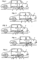
- Figures 3 to 5 are schematic elevational views showing a motor vehicle equipped with a variant of the device illustrated in Figures 1 and 2, Figure 3 showing the device in the inactive position, Figure 4 showing the device occupying its above intermediate position in which the aforementioned means are placed on the ground, while FIG. 5 shows the device in the active position in which it lifts the vehicle when it is fraudulently started.
- FIG. 6 is a view in elevation and in section showing, on a larger scale, the anti-theft device illustrated in FIGS. 3 to 5.
- FIG. 7 is a plan view corresponding to FIG. 6.
- FIG. 8 is a sectional view along the line VIII-VIII of FIG. 7.
- FIG. 9 is a view corresponding to FIG. 7 and showing a variant of the anti-theft device illustrated in this FIG. 7.
- FIG. 10 is a sectional view along line X-X in FIG. 9.
- FIG. 11 is a view similar to FIG. 6 and showing a variant of the anti-theft devices illustrated in FIGS. 6 to 10.
- FIG. 12 is a view similar to FIG. 11 and showing a variant of the anti-theft device illustrated in this FIG. 11.
- Figure 13 is a plan view corresponding to Figure 12.
- the anti-theft device 1 for a vehicle comprises means 2 associated with the vehicle 3 and arranged to occupy two positions, an inactive position (FIG. 1) in which they are located away from the ground 4 when said device is not engaged, that is to say for a normal setting in motion of the vehicle and during the movement of the latter, and an active position (Figure 2), when the vehicle is stopped and that it is desired to protect it against theft, in which they cause the lifting of said vehicle so that at least one of the drive wheels 5 of the latter no longer has sufficient grip on the ground so that the vehicle can be moved thanks to its motor, or no longer in contact with the ground, lockable means not shown being provided for moving the means 2 from their inactive position to their active position and vice versa as well as for maintaining them in the chosen position.
- the means 2 are fixed under the vehicle, to the floor or to the chassis 6 of the latter, near the drive axle 7.
- the means 2 are constituted by a rod 7 'substantially perpendicular to the ground and guided in a box 8, fixed to the floor 6 of the vehicle, to move along its longitudinal axis to occupy one of the two aforementioned positions.
- This rod 7 ′ is controlled by the above-mentioned locking means, not shown, such as a pressurized fluid jack, an electric motor driving a pinion meshing with a toothing produced on the rod.
- the means 2 are arranged to occupy a third intermediate position (see FIG.
- the means 2 comprise a stand 9 which extends substantially parallel to the vertical plane passing through the longitudinal axis of the vehicle.
- the end 10 of this stand is wedged on a shaft 11 which can rotate about an axis, of trace 12 and fixed relative to the vehicle, which is substantially horizontal and perpendicular to the vertical plane passing through the longitudinal axis of the vehicle.
- the end 13 of the stand, fitted with a shoe 14, is free and directed towards the front of the vehicle.
- the distance which separates the axis 12 from the shaft 11 is greater than the distance which separates this axis from the ground 4 when the vehicle occupies a position such that the tire of at least one of its drive wheels 5 is practically does not offer more grip with the ground, or is no longer in contact with the latter (distance D - Figure 5).
- the shaft 11 is supported, so as to be able to rotate about its axis 12, in a box 8 fixed to the floor 6 of the vehicle, this box containing the aforementioned means 5 ′ provided for moving the stand 9 between its inactive position in which it is substantially parallel to the ground and its intermediate position in which it rests obliquely on the ground and vice versa.
- These means 5 comprise an endless screw 15 supported in the housing 8 so that its axis is located in a plane perpendicular to the axis 12 of the shaft 11, means, such as electric motor 16, arranged to rotate the worm in one direction or the other around its axis, a threaded element 17 arranged on the worm 15 so that it can move along the axis of this screw when it is rotated, means 18 cooperating with the element 17 to prevent its rotation about the axis of the screw 15 and a connecting rod 19 connecting the stand 9 to said element 17, this connecting rod being arranged so that, on the one hand, the displacement of the element 17 on the screw 15 causes the crutch 9 to pivot about the axis 12, and, on the other hand, that the automatic displacement of the crutch from its intermediate position to its aforesaid active position, in which it causes the vehicle to be raised, can be carried out without the connecting rod 19 exerting a push r the tapped element 17, so that the movement of the connecting rod 19, when the stand moves from its intermediate position to its
- This connecting rod 19 is wedged, at one of its ends, on the shaft 11 and has, at its end 20, a buttonhole 21 in which is engaged a pin 22 parallel to the shaft 11 and carried by the threaded element 17.
- This buttonhole 21 is shaped so that the pin 22 is free relative to the connecting rod 19 when the stand moves from its intermediate position to the active position causing the lifting ment of the vehicle, which makes it possible to avoid any force on the element 17 and on the endless screw 15, this buttonhole 21 also being profiled so that the pin 22 acts on the connecting rod 19 when the screw 15 is rotated, in one direction or the other, to bring the stand 9 from its intermediate position to its inactive position and vice versa.
- the aforementioned means 18 preventing the rotation of the element 17 around the screw 15 can be formed, as shown in Figures 7 and 8, by a fixed rod 23 supported in the housing 8, parallel to this screw 15, and cooperating with a opening 24, of section slightly greater than that of the rod 23, formed in the threaded element 17.
- These means 18 could also, as shown in FIGS.
- the inertia of the means 5 ′ is such that the stand 9 cannot pass from its inactive position to its intermediate position under the action of its own weight nor under the action of this weight combined with vibrations and shocks transmitted to these various elements when the vehicle is in motion.
- the housing 8 comprises a fixed stop 25 disposed on the trajectory of the stand 9. This stop 25 is arranged to immobilize said stand, when the latter goes from its intermediate position to its active position, in which the vehicle is lifted either before it reaches a vertical position, or when it reaches this vertical position.
- the electric motor 16 is controlled by a key switch, not shown, arranged inside the vehicle.
- This switch will advantageously be of the type with automatic return of the key to the neutral position, the only position authorizing the release and entry of the key, while the wires connecting the switch to the motor 16 will advantageously be placed under a metal sheath.
- the motor 16 When the motor 16 is supplied, its supply is automatically cut off by thermal switches opening during the mechanical overload of the motor when the stand 9 has reached its inactive position or its intermediate position.
- an inverter relay is inserted in the electrical circuit of the engine 16 so that this relay is open and kept open when the vehicle's contact switch is closed, an indicator light being advantageously provided, in the aforementioned circuit, to be energized when the stand 9 occupies its intermediate position.
- the anti-theft device illustrated in Figures 3 to 10 is intended to make it impossible to fraudulently move a vehicle in forward gear. If one also wanted to prevent the vehicle from moving in reverse, one could use, according to the invention, an anti-theft device comprising, as shown in FIGS. 11 to 13, two crutches 9 and 9 ′, the free end 13 of the stand 9 being directed towards the front of the vehicle while the free end 13 ′ of the stand 9 ′ is directed towards the back.
- the crutches 9 and 9 ' are each wedged on a shaft 11, these shafts 11 being parallel.
- the shafts 11 are arranged on either side of the electric motor 16 which simultaneously controls the two legs so that they simultaneously occupy either their active position or their inactive position.
- This control is carried out by means of two endless screws 15 and 15 'aligned, arranged on either side of the motor 16 and driven simultaneously by the latter, and whose pitch is reversed, and two tapped elements 17 and 17 "each cooperating with at least one connecting rod 19 and 19".
- the shafts 11 are arranged on the same side of the motor 16, which makes it possible to reduce the size of the device compared to that shown in FIG. 11 as well as to simplify its construction.
- One of these shafts 11 is controlled by the motor 16, the worm 15, the threaded part 17 and the connecting rods 19 and 19 '.
- This shaft 11 carries at least one toothed wheel 26, wedged on said shaft, which meshes with a corresponding toothed wheel 26 'wedged on the other shaft 11.
- the diameters of the toothed wheels 26 and 26' are equal so that the movements of the crutches 9 and 9 ', wedged on these shafts 11, are performed simultaneously in the opposite direction and so that the amplitudes of these movements are identical.
- the devices illustrated in Figures 10 to 13 have, on their housing 8, one or two fixed stops 25 to limit the movement of the crutches as described above.
- the housing has openings, through which it can be fixed, which are arranged opposite the locations of the screws and a screen, located in the housing and fixed to the threaded element 17, which is arranged to close off said openings when the element 17 occupies its position corresponding to the active position of the stand whose movement it controls.
- either the anti-theft device should be placed so that it can lift the vehicle so that a wheel on each of the drive axles loses its grip, or a device arranged close to each of these drive axles.
Applications Claiming Priority (4)
| Application Number | Priority Date | Filing Date | Title |
|---|---|---|---|
| BE894225 | 1982-08-27 | ||
| BE894225 | 1982-08-27 | ||
| BE895863 | 1983-02-09 | ||
| BE895863 | 1983-02-09 |
Publications (2)
| Publication Number | Publication Date |
|---|---|
| EP0102339A2 true EP0102339A2 (de) | 1984-03-07 |
| EP0102339A3 EP0102339A3 (de) | 1985-04-03 |
Family
ID=25660049
Family Applications (1)
| Application Number | Title | Priority Date | Filing Date |
|---|---|---|---|
| EP83870062A Withdrawn EP0102339A3 (de) | 1982-08-27 | 1983-06-17 | Vorrichtung zur Diebstahlsicherung |
Country Status (1)
| Country | Link |
|---|---|
| EP (1) | EP0102339A3 (de) |
Cited By (6)
| Publication number | Priority date | Publication date | Assignee | Title |
|---|---|---|---|---|
| GB2218952A (en) * | 1988-05-27 | 1989-11-29 | Christopher John Wilson | Vehicle anti-theft apparatus |
| GB2242405A (en) * | 1990-03-26 | 1991-10-02 | Elvi Marjatta Gatfield | Vehicle anti-theft device |
| WO1992005981A1 (fr) * | 1990-09-27 | 1992-04-16 | Sassi Leopold | Dispositif de securite antivol pour remorques de poids lourds |
| GB2262076A (en) * | 1991-12-03 | 1993-06-09 | Donald Allen | Immobilising vehicles |
| GB2286163A (en) * | 1994-02-08 | 1995-08-09 | John Parsons | Vehicle security system |
| DE19622501B4 (de) * | 1995-06-08 | 2004-07-15 | Helmut Appelrath | Vorrichtung zur Verhütung von Diebstählen abgestellter Kraftfahrzeuge |
Citations (6)
| Publication number | Priority date | Publication date | Assignee | Title |
|---|---|---|---|---|
| DE375847C (de) * | 1923-05-19 | Max Weichold | Sicherungsvorrichtung gegen Diebstahl von Kraftfahrzeugen | |
| US1456272A (en) * | 1920-10-11 | 1923-05-22 | Andrew T Holder | Theft-preventive device |
| US2017749A (en) * | 1932-02-23 | 1935-10-15 | Kenneth A Brainard | Vehicle blocking device |
| US2218733A (en) * | 1938-03-22 | 1940-10-22 | Roy T Watts | Electric lifting jack |
| AT165165B (de) * | 1947-03-24 | 1950-01-25 | Wilhelm Dipl Ing Dr Techn Zorn | Vollautomatische Wagenhebeeinrichtung |
| FR2495555A1 (fr) * | 1980-12-05 | 1982-06-11 | Neiman Sa | Dispositif antivol pour vehicules automobiles |
-
1983
- 1983-06-17 EP EP83870062A patent/EP0102339A3/de not_active Withdrawn
Patent Citations (6)
| Publication number | Priority date | Publication date | Assignee | Title |
|---|---|---|---|---|
| DE375847C (de) * | 1923-05-19 | Max Weichold | Sicherungsvorrichtung gegen Diebstahl von Kraftfahrzeugen | |
| US1456272A (en) * | 1920-10-11 | 1923-05-22 | Andrew T Holder | Theft-preventive device |
| US2017749A (en) * | 1932-02-23 | 1935-10-15 | Kenneth A Brainard | Vehicle blocking device |
| US2218733A (en) * | 1938-03-22 | 1940-10-22 | Roy T Watts | Electric lifting jack |
| AT165165B (de) * | 1947-03-24 | 1950-01-25 | Wilhelm Dipl Ing Dr Techn Zorn | Vollautomatische Wagenhebeeinrichtung |
| FR2495555A1 (fr) * | 1980-12-05 | 1982-06-11 | Neiman Sa | Dispositif antivol pour vehicules automobiles |
Cited By (10)
| Publication number | Priority date | Publication date | Assignee | Title |
|---|---|---|---|---|
| GB2218952A (en) * | 1988-05-27 | 1989-11-29 | Christopher John Wilson | Vehicle anti-theft apparatus |
| GB2218952B (en) * | 1988-05-27 | 1992-06-03 | Christopher John Wilson | Anti-theft apparatus |
| GB2242405A (en) * | 1990-03-26 | 1991-10-02 | Elvi Marjatta Gatfield | Vehicle anti-theft device |
| GB2242405B (en) * | 1990-03-26 | 1993-11-10 | Elvi Marjatta Gatfield | Vehicle anti-theft device |
| WO1992005981A1 (fr) * | 1990-09-27 | 1992-04-16 | Sassi Leopold | Dispositif de securite antivol pour remorques de poids lourds |
| US5426961A (en) * | 1990-09-27 | 1995-06-27 | Rimbaud; Pierre | Antitheft security device for trailers of trucks |
| GB2262076A (en) * | 1991-12-03 | 1993-06-09 | Donald Allen | Immobilising vehicles |
| GB2262076B (en) * | 1991-12-03 | 1995-10-18 | Donald Allen | Immobilising vehicles |
| GB2286163A (en) * | 1994-02-08 | 1995-08-09 | John Parsons | Vehicle security system |
| DE19622501B4 (de) * | 1995-06-08 | 2004-07-15 | Helmut Appelrath | Vorrichtung zur Verhütung von Diebstählen abgestellter Kraftfahrzeuge |
Also Published As
| Publication number | Publication date |
|---|---|
| EP0102339A3 (de) | 1985-04-03 |
Similar Documents
| Publication | Publication Date | Title |
|---|---|---|
| EP0972694B1 (de) | Elektrisch betriebene Klemmvorrichtrung zum Verstellen der Position eines Teiles bezüglich eines anderen Teiles | |
| FR2793749A1 (fr) | Dispositif de securite contre le vol d'un vehicule automobile | |
| FR2706846A1 (de) | ||
| FR2679504A1 (fr) | Serrure de blocage de la direction d'un vehicule. | |
| EP2479073B1 (de) | Diebstahlsicherung für Lenksäule eines Kraftfahrzeugs | |
| EP0102339A2 (de) | Vorrichtung zur Diebstahlsicherung | |
| EP0989038A1 (de) | Steuersäule-Diebstahlsicherung mit Mittel zur Bolzenverriegelung | |
| FR2809368A1 (fr) | Colonne de direction a manchon antivol, ensemble comprenant une telle colonne et une serrure, et vehicule automobile correspondant | |
| FR2768163A1 (fr) | Barriere pour emplacement personnel de parking | |
| FR2889142A1 (fr) | Dispositif antivol permettant de commander le verrouillage d'une colonne de direction d'un vehicule automobile | |
| FR2871759A1 (fr) | Dispositif antivol de direction a verrou inserable notamment pour vehicule automobile | |
| EP3233590B1 (de) | Diebstahlsicherung für eine lenksäule eines kraftfahrzeugs | |
| FR2963917A1 (fr) | Vehicule comportant un dispositif de blocage antivol des roues directrices | |
| CH653628A5 (en) | Assistance device for manoeuvring a vehicle of the semi-trailer type | |
| FR2790017A1 (fr) | Dispositif de reservation controlee d'un emplacement de garage, d'un acces ou d'un passage | |
| EP3670271B1 (de) | Bewegungsvorrichtung einer kamera für ein motorgetriebenes fahrzeug | |
| FR2563794A1 (fr) | Dispositif antivol pour vehicules | |
| FR2673891A1 (fr) | Dispositif d'attelage a boule escamotable et demontable. | |
| FR2911560A1 (fr) | Dispositif de protection des pietons en cas de choc frontal avec un vehicule automobile et vehicule automobile equipe d'un tel dispositif de protection des pietons | |
| FR2700148A1 (fr) | Dispositif antivol rendant impossible la conduite d'un véhicule automobile s'il est équipé d'un volant de direction. | |
| EP2239171B1 (de) | Lenkradschloss für Lenksäule | |
| FR2732299A1 (fr) | Systeme de verrouillage de securite pour un ensemble de colonne de direction reglable en position notamment de vehicule automobile | |
| EP0550310A1 (de) | Diebstahlsicherungsvorrichtung für Kraftfahrzeuge | |
| FR2745538A1 (fr) | Dispositif antivol pour vehicule | |
| EP0112735A1 (de) | Hilfsapparat für Anhängerhandantrieb, insbesondere für Wohnwagen |
Legal Events
| Date | Code | Title | Description |
|---|---|---|---|
| PUAI | Public reference made under article 153(3) epc to a published international application that has entered the european phase |
Free format text: ORIGINAL CODE: 0009012 |
|
| AK | Designated contracting states |
Designated state(s): AT BE CH DE FR GB IT LI LU NL SE |
|
| PUAL | Search report despatched |
Free format text: ORIGINAL CODE: 0009013 |
|
| AK | Designated contracting states |
Designated state(s): AT BE CH DE FR GB IT LI LU NL SE |
|
| 17P | Request for examination filed |
Effective date: 19851003 |
|
| 17Q | First examination report despatched |
Effective date: 19860411 |
|
| D17Q | First examination report despatched (deleted) | ||
| STAA | Information on the status of an ep patent application or granted ep patent |
Free format text: STATUS: THE APPLICATION IS DEEMED TO BE WITHDRAWN |
|
| 18D | Application deemed to be withdrawn |
Effective date: 19870812 |