EP0102211A2 - Modular tile with positioning means for use with an access floor panel system - Google Patents
Modular tile with positioning means for use with an access floor panel system Download PDFInfo
- Publication number
- EP0102211A2 EP0102211A2 EP83304620A EP83304620A EP0102211A2 EP 0102211 A2 EP0102211 A2 EP 0102211A2 EP 83304620 A EP83304620 A EP 83304620A EP 83304620 A EP83304620 A EP 83304620A EP 0102211 A2 EP0102211 A2 EP 0102211A2
- Authority
- EP
- European Patent Office
- Prior art keywords
- tile
- panels
- access floor
- floor panel
- modular
- Prior art date
- Legal status (The legal status is an assumption and is not a legal conclusion. Google has not performed a legal analysis and makes no representation as to the accuracy of the status listed.)
- Granted
Links
Images


Classifications
-
- E—FIXED CONSTRUCTIONS
- E04—BUILDING
- E04F—FINISHING WORK ON BUILDINGS, e.g. STAIRS, FLOORS
- E04F15/00—Flooring
- E04F15/02—Flooring or floor layers composed of a number of similar elements
- E04F15/024—Sectional false floors, e.g. computer floors
- E04F15/02405—Floor panels
- E04F15/02417—Floor panels made of box-like elements
- E04F15/02423—Floor panels made of box-like elements filled with core material
Definitions
- the present invention essentially comprises new technology in the development of a modular tile with means to position, index and maintain position to an access floor panel system, while remaining removable and replaceable without the use of adhesive indexing tools, or fixtures.
- access flooring comprised of a modular embodiment of a rigid structural floor panel supported on pedestal columns, being used as an accessible floor providing an underfloor space or cavity for use in distributing HVAC, electrical power, CRT, and other communication connections, in the office space
- the initial access flooring for such purposes had the carpet finish bonded to each modular panel at the factory, where the finish could be exactly indexed by fixturing and manufacturing methods which maintained the carpet module to the exact dimensions of the panel module.
- This bonding and registration provided the ability to move individual panels and their covering as one unit from space to space in the building, which allowed for movement of electrical, telephone and HVAC penetrations to other locations as offices were moved within the building.
- the carpet could, with difficulty, be stripped from the access floor panel, but required similar indexing and manufacturing means as provided in the factory, to index and apply in a modular fashion new carpet to the access floor panel.
- carpet tiles which typically are modular carpet squares with a more rigid vinyl backing, to hold a tile flat when laid.
- carpet tile although modular, has no means to maintain a consistent module with the access floor panel, and typically is of a different module size.
- carpet tile also requires use of a releasable adhesive, in total or in part, to prevent shifting of the tile on the access floor panel surface.
- tiles of this type because they are not modular to the access floor panel, requires significant additional carpet stock to be maintained, so that when offices are relocated with their supporting service penetrations through the access floor, the tiles that do not line up in the new area, must be discarded, and replaced with new tiles.
- Typical additional tile stock based on a rate of 2.5 affected tiles per move, an office-move rate of 25% per year, and a 10-year life cycle, requires 25% additional tiles to be purchased initially, which will insure uniformity of carpet color over the life of the building.
- each demonstrates positioning of a tile or fixture by use of projections, dimples, or spring clips, each is functioning on a continuous surface, and maintains no modularity to a modular substructure. Should a large section of the substructure require removal, multiple tile or fixture units which would require removal for access.
- Patent No. 2,135,118 to Stewart demonstrates embodiments of rough locating projections and spring clip arrangements that are then cemented or adhered in place for maintenance of final positioning.
- the tiles or fixtures are modular to one another, but are not modular to a modular substrate.
- a flat rectangular holding frame member is provided on one side with adhesive tape adjacent the edge thereof, which is covered by a peel-off film which, upon removal, allows the frame to be applied to the surface of a wall for adherence thereto, and on the other side, is provided with a snap fastener for removably holding a flat, domino decoration-bearing rectangular face member which is similar in size and shape to that of the frame member, having a mating snap fastener on the back thereof, in place thereon, so that a wall decorated with a plurality of different domino spots, or blanks, can be arranged on the frame member at will without removing the frame members from the wall surface.
- Destito a series of frames are attached to the wall, which itself is not modular, by adhesion and, while the frames are modular to one another, such are not modular to the wall surface.
- Destito relates merely to a wall decorating device rather than to a modular tile for an access floor panel system as utilized in the present invention.
- Patent No. 3,341,996 to Jones, et al, issued 9/19/67 which shows a magnetic backing material or substrate material for use in holding modular tiles to a substrate.
- This prior art does not demonstrate any modular fixing to the substructure, although the tiles may be made modular to one another. Use of this prior art would allow for application of tile modules to a panel in a similar fashion to factory-applied carpet, but would require similarly indexing and other manufacturing means to maintain modular alignment to the access floor panel system.
- the prime object of this present invention is to provide a tile with a means to be positively located on an access floor panel, being field replaceable and removable without the use of glue, indexing tools or fixtures, through the tile's bottom surface or the panel's top surface having a configuration which orients the tile to the access floor panel, the size of said carpet tile being consistent and modular with each and every access floor panel in the system.
- a tile can be manufactured, with positively located projections or recesses, which can be indexed into die formed holes or projections in the access floor panel, respectively, providing a positive index and modular to modular control for each tile to each and every access floor panel.
- the advantages of this invention are that each access floor panel provided, forms a permanent, yet portable fixture for each tile provided. The positioning of the tile, not only indexes the tile to the access floor module, but prevents shifting of the tile on the module, and simplifies the future replacement of the floor covering. As offices are relocated in the building, and the service penetrations are similarly moved, the access floor panel, and its service fitting, together with its tile, can be relocated to the new location, without loss of tiles due to misalignment of penetrations.
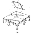
- FIGURE 1 shown therein is a perspective view, partially exploded, illustrating a modular tile 1 which is operatively associated with an access floor panel 2 made of, for example, steel or plastic. As shown in FIGURE 1, the series of access floor panels 2 form an access floor panel system upon which is mounted one or more tiles 1.
- Reference number 3 indicates a top surface portion of each access floor panel 2 while reference number 4 indicates at least one projection extending downwardly from a bottom surface portion 28 of the tile 1.
- Reference number 5 denotes an edge flange of each access floor panel 2.
- Each tile can be provided with an optional projection 6 for directional control and orientation of the tile 1 with respect to each access floor panel 2.
- Reference number 7 indicates the side wall of each access floor panel 2 while reference number 8 indicates a magnetic or pressure sensitive adhesive perimeter of each tile 1 which also is optional and which serves to prevent lifting or curling of the tile 1 along the edge portion or perimeter 9 thereof or at a corner 11 thereof such that each tile 1 is removable and replaceable without the use of indexing tools or fixtures.
- Reference number 10 indicates a positioning hole for on module installation.
- the projections 4 in each tile 1 serve to position, index and maintain position modularity of the tile 1 relative to the access floor panel system.
- the projections 4 cooperating with the positioning holes 10 are of corresponding configuration so as to orient each tile 1 to each of the panels 2 such that each tile is removable and replaceable without the use of indexing tools or fixtures and such that each tile is substantially of panel module size.
- the modularity of the panels 2 and also the tiles 1 are dimensionally consistent such that each tile can be relocated on any other panel so as to maintain a consistent modular interface.
- each tile 1 serves as a positioning and indexing means which indexes into only one positioning hole 10 formed in each of the floor panels 2 due to engagement of adjacent edge portions or perimeters 14 of each tile upon being mounted on two or more adjacent access floor panels 2.
- An adjustable pedestal 22 in combination with a support platform 24 serves to support each of the access floor panels 2 from a floor in a conventional manner.
- the manner of use of the adjustable pedestal 22 and support platform 24 are apparent from a review of FIGURES 1-3.
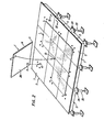
- FIGURE 2 serves to illustrate a view similar to that of FIGURE 1 but showing an alternative arrangement of tiles 1 on the access floor panels 2. More particularly, while the arrangement of projections 4 on the bottom surface portion 28 of each tile 1 is the same as that as shown in FIGURE 1, the arrangement of the positioning holes 10 differs from that of FIGURE 1 insofar as the positioning holes are located in a central portion of each access floor panel 2 so as to allow for overlapping of a single tile 1 onto adjacent quarter sections of four panels. Otherwise, the embodiment shown in FIGURE 2 directly corresponds to the structural element shown in FIGURE 1.
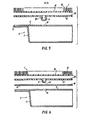
- FIGURE 3 again relates to a vertical cross-sectional view taken on lines III-III of FIGURE 2 and serves to more clearly illustrate the manner in which the panels 2 are supported by pedestal 22 and support platform 24 as well as the cooperative engagement of edge portion or perimeter 9 of each panel and the cooperative engagement of edge portion or perimeter 14 of each tile 1.
- reference number 15 denotes a carpet pile or similar surface such as, for example, a vinyl surface, an asbestos surface, a rubber surface or a similar type of surface found to be acceptable in the floor covering industry.
- Reference number 16 serves to indicate a primary backing of carpet pile 15 while reference number 18 denotes an adhesive bond for the carpet primary backing 16.
- a backing structure 19 is utilized to serve as a further backing for the primary backing 16 wherein the projections 4 are integral with and extend from the plane of backing structure 19 for indexing into positioning hole 10 formed in access floor panel 2. Backing structure 19 therefore serves to engage top surface portion 3 of access floor panel 2.
- FIGURE 5 shows an alternate embodiment of the structure of FIGURE 4 wherein the projection 4 extending from backing structure 19 is formed with undercut snaps 20 for a more secure engagement with positioning hole 10 to prevent uplift.
- FIGURE 6 shows yet another alternate embodiment of the structure of FIGURE 4 which utilizes a conductor 21 in the form of a backing.
- projection 4 extends through a hole 23 formed in backing structure 19 and also cooperates with projection hole 10 formed in floor panel 2. Accordingly, projection 4 extending from conductor 21 also serves to position, index and maintain the position of the tile 1 relative to the access floor panel 2 wherein projection 4 and conductor 21 are made of a conductive material for providing improved resistance to static electricity build-up on the surface of the tile while also being of a configuration which orients the tile 1 to each of the panels 2 such that the tile 1 is removable and replaceable without the use of the aforementioned indexing tools or fixtures.
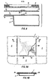
- FIGURES 7A-7E serve to illustrate yet another embodiment of the present invention wherein FIGURE 7A illustrates an underside perspective view of the tile 1 while FIGURE 7B shows a vertical cross-sectional fragmentary view taken along line B-B of FIGURE 7A. These figures serve to illustrate a rim projection 26 extending downwardly along the periphery of the tile 1 such that bottom portion 28 is completely surrounded by rim projection 26.
- FIGURE 7C illustrates a top view of the floor panel 2 associated with the tile 1 of FIGURE 7A while FIGURE 7 D illustrates a vertical cross-sectional view on line C-C of FIGURE 7C.
- reference number 30 indicates a hole or recess formed in the periphery of floor panel 2 while reference number 32 indicates an offset panel top surface.
- FIGURE 7E sets forth a vertical cross-sectional view showing engagement of rim projection 26 with offset panel top surface 32 and which therefore serves to position, index, and maintain position modularity of the tile 1 relative to the access floor panel 2 so that again, tile 1 is removable and replaceable without the use of indexing tools or fixtures and the tile is substantially of the panel module size.
- the modularity of the panel 2 is dimensionally consistent such that the tile 1 can be relocated on any of a number of panels 2 so as to maintain a consistent modular interface.
- FIGURE 7F illustrates a vertical cross-sectional view of a variation on the embodiment of FIGURE 7E wherein an offset tile lower surface 33 is used and which is cooperatively engageable with a rim projection 35 in the top surface of panel 2.
- the features of this embodiment are otherwise identical structurally and functionally to that of the embodiment in FIGURE 7E. Therefore, in the embodiment of FIGURE 7E, each of the panels 2 has at least one positioning offset 32 formed along the periphery thereof as well as rim projection 26 extending from and along the periphery of tile 1 which indexes in the positioning offset 32.
- the tile 1 has a positioning offset 33 formed along the periphery thereof and the rim projection 35 extends from and along the periphery of each of the panels 2 so as to index in the positioning offset 33 formed along the periphery of the tile 1.
- the above noted magnetic or pressure sensitive perimeter 8 can also be utilized if desired.
- FIGURE 8 illustrates an exploded cross-sectional view which is similar to that of FIGURE 4 but which shows an alternative embodiment of tile projection 4.
- a projection 34 is provided so as to extend from the top surface portion 3 of each floor panel 2 while the tile 1 has at least one positioning recess 36 formed therein such that projection 34 indexes into or with positioning hole or recess 36 formed in the tile.
- this embodiment is similar structurally and functionally to the embodiment shown in FIGURES 1-4.
- FIGURES 9A and 9B in this embodiment at least one peripheral recessed portion 40 is formed in each panel 2 while at least one corresponding peripheral projection 38 extends from the tile 1.
- the peripheral projection 38 is oriented so as to index in recessed portion 40 of each panel to again allow for orientation of the tile 1 to each of the panels 2 such that the tile is removable and replaceable without the use of indexing tools or fixtures and such that the tile is substantially of the panel module size.
- the modularity of panels is dimensionally consistent such that the tile 1 can be relocated on any of the panels 2 so as to maintain a consistent modular interface.
- the use of a magnetic or pressure sensitive adhesive perimeter 8 (not shown in FIGURES 9A and 9B) can also be utilized in this embodiment.
- the positioning holes or recesses and corresponding projections are located at positions in from the edges of the panel and tile units equal to a quarter of the edge length. In this way, the tiles can be laid either on-module as shown in Figure 1 or off-module as shown in Figure 2.
Abstract
Description
- The present invention essentially comprises new technology in the development of a modular tile with means to position, index and maintain position to an access floor panel system, while remaining removable and replaceable without the use of adhesive indexing tools, or fixtures.
- With the advent of access flooring, comprised of a modular embodiment of a rigid structural floor panel supported on pedestal columns, being used as an accessible floor providing an underfloor space or cavity for use in distributing HVAC, electrical power, CRT, and other communication connections, in the office space, problems arose with the finish on the floor which was typically carpet. The initial access flooring for such purposes had the carpet finish bonded to each modular panel at the factory, where the finish could be exactly indexed by fixturing and manufacturing methods which maintained the carpet module to the exact dimensions of the panel module. This bonding and registration provided the ability to move individual panels and their covering as one unit from space to space in the building, which allowed for movement of electrical, telephone and HVAC penetrations to other locations as offices were moved within the building.
- When this factory-applied carpet required replacement, the carpet could, with difficulty, be stripped from the access floor panel, but required similar indexing and manufacturing means as provided in the factory, to index and apply in a modular fashion new carpet to the access floor panel.
- Typical prior art of this type of construction is shown in U.S. Patent No. 3,681,882 to Bettinger, issued 8/8/72; No. 3,811,237 to Bettinger, issued 5/21/74; No. 4,085,557 to Tharp, issued 4/25/78; and No. 3,548,559 to Levine, issued 12/22/70.
- Although application of carpet to the access floor panel in this manner provided a consistent module, other problems were created. Typically, in a building cycle, the access floor is installed prior to other services being installed in the building such as a sprinkler system, drywall, and electrical and telephone distribution. Since these services were being installed over a finished carpeted floor, efforts were required to protect this floor while these other trades were working. Protection was expensive and often inadequate, causing costly cleaning and, in some cases, replacement of both carpet and panel, due to damage to the bonded finish.
- In recent years, this problem has been overcome by use of carpet tiles which typically are modular carpet squares with a more rigid vinyl backing, to hold a tile flat when laid. Such carpet tile, although modular, has no means to maintain a consistent module with the access floor panel, and typically is of a different module size. Normally, such carpet tile also requires use of a releasable adhesive, in total or in part, to prevent shifting of the tile on the access floor panel surface.
- Use of tiles of this type, because they are not modular to the access floor panel, requires significant additional carpet stock to be maintained, so that when offices are relocated with their supporting service penetrations through the access floor, the tiles that do not line up in the new area, must be discarded, and replaced with new tiles. Typical additional tile stock, based on a rate of 2.5 affected tiles per move, an office-move rate of 25% per year, and a 10-year life cycle, requires 25% additional tiles to be purchased initially, which will insure uniformity of carpet color over the life of the building.
- Prior art in the access floor industry has failed to maintain the tile module with the access floor module, to reduce this excessive initial cost, in any other manner other than factory-glued carpet with its own set of problems. Attempts have been made to field index and laminate carpet access floor panels, but the extra handling costs and reduced efficiency is not cost effective.
- The mere use of projection on a tile or fixture for location purposes is not new, as shown by the following prior U.S. Patents:

- In reviewing said prior art patents, although each demonstrates positioning of a tile or fixture by use of projections, dimples, or spring clips, each is functioning on a continuous surface, and maintains no modularity to a modular substructure. Should a large section of the substructure require removal, multiple tile or fixture units which would require removal for access.
- In Patent No. 1,704,537 to Haines, the position and modular tile when indexed on the substrate is then cemented to the substrate, and the protrusions are used for initial positioning only, but fixity is maintained by the tile cemented to the substrate.
- Patent No. 2,135,118 to Stewart, demonstrates embodiments of rough locating projections and spring clip arrangements that are then cemented or adhered in place for maintenance of final positioning. Here, as in other prior art, the tiles or fixtures are modular to one another, but are not modular to a modular substrate.
- In U.S. Patent No. 4,143,496 to Destito, a flat rectangular holding frame member is provided on one side with adhesive tape adjacent the edge thereof, which is covered by a peel-off film which, upon removal, allows the frame to be applied to the surface of a wall for adherence thereto, and on the other side, is provided with a snap fastener for removably holding a flat, domino decoration-bearing rectangular face member which is similar in size and shape to that of the frame member, having a mating snap fastener on the back thereof, in place thereon, so that a wall decorated with a plurality of different domino spots, or blanks, can be arranged on the frame member at will without removing the frame members from the wall surface. It can therefore be appreciated that in Destito, a series of frames are attached to the wall, which itself is not modular, by adhesion and, while the frames are modular to one another, such are not modular to the wall surface. Furthermore, Destito relates merely to a wall decorating device rather than to a modular tile for an access floor panel system as utilized in the present invention.
- In other parallel prior art to the present invention, such as shown in U.S. Patent No. 3,862,874 to Hopper, et al, issued 1/20/75, the modular rug unit is shown'which is mechanically fastened to one of a number of embodiments of tape substructures which allow for individual and/or entire unit removal from the substrate. This requires layout of the tape arrangement in an overall, not modular pattern, and would not provide individual access through the substrate, in a consistent modular fashion.
- One other parallel U.S. patent which demonstrates similar technology to one embodiment of the present patent is Patent No. 3,341,996 to Jones, et al, issued 9/19/67 which shows a magnetic backing material or substrate material for use in holding modular tiles to a substrate. This prior art does not demonstrate any modular fixing to the substructure, although the tiles may be made modular to one another. Use of this prior art would allow for application of tile modules to a panel in a similar fashion to factory-applied carpet, but would require similarly indexing and other manufacturing means to maintain modular alignment to the access floor panel system.
- By such exploration, it has been determined that the prior art, although demonstrating some similar embodiments to embodiments included in the present invention, does not demonstrate the key features provided in the current invention.
- The prime object of this present invention is to provide a tile with a means to be positively located on an access floor panel, being field replaceable and removable without the use of glue, indexing tools or fixtures, through the tile's bottom surface or the panel's top surface having a configuration which orients the tile to the access floor panel, the size of said carpet tile being consistent and modular with each and every access floor panel in the system.
- It has been found that a tile can be manufactured, with positively located projections or recesses, which can be indexed into die formed holes or projections in the access floor panel, respectively, providing a positive index and modular to modular control for each tile to each and every access floor panel. The advantages of this invention are that each access floor panel provided, forms a permanent, yet portable fixture for each tile provided. The positioning of the tile, not only indexes the tile to the access floor module, but prevents shifting of the tile on the module, and simplifies the future replacement of the floor covering. As offices are relocated in the building, and the service penetrations are similarly moved, the access floor panel, and its service fitting, together with its tile, can be relocated to the new location, without loss of tiles due to misalignment of penetrations.
- Various objects, features and attendant advantages of the present invention will be more fully appreciated as the same becomes better understood from the following detailed description when considered in connection with the accompanying drawings in which like reference characters designate like or corresponding parts throughout the several views and wherein:
- FIGURE 1 is a perspective view, partially exploded, showing an access floor panel system with a tile shown exploded in relationship with the access floor panels;
- FIGURE 2 is a view similar to FIGURE 1, showing an alternate arrangement of tiles on the access floor panels;
- FIGURE 3 is a vertical cross-sectional view taken on lines III-III of FIGURE 2;
- FIGURE 4 is an exploded vertical cross-sectional view showing in greater detail the structure of FIGURE 1;
- FIGURE 5 is a view similar to FIGURE 4 showing an alternative configuration of the projection on the tile;
- FIGURE 6 is a view similar to FIGURE 4 showing yet another type of projection on the tile;
- FIGURE 7A is an underside perspective view of the tile of an alternate embodiment;
- FIGURE 7B is a vertical cross-sectional and fragmentary view on line B-B of FIGURE 7A;
- FIGURE 7C is a top view of an access floor panel associated with the tile of FIGURE 7A;
- FIGURE 7D is a vertical cross-sectional view on line C-C of FIGURE 7C;
- FIGURE 7E is a vertical cross-sectional view showing the engagement of the elements show in FIGURE 7A and FIGURE 7C;
- FIGURE 7F shows a vertical cross-sectional view of another embodiment similar to that of FIGURE 7E and showing the engagement of various elements;
- FIGURE 8 is an exploded cross-sectional view similar to FIGURE 4 but showing an alternative embodiment of the tile projections;
- FIGURE 9A is a plan view of a further embodiment with an adjacent floor panel in phantom lines; and
- FIGURE 9B is a vertical cross-sectional view on line B-B of FIGURE 9A.
- To provide an understanding of certain terms used in the specification and claims of this application, the following definitions are set forth:
-
- System Module - the nominal size (length and width) of each access floor panel unit; also the nominal spacing of access floor panel supporting members laterally and longitudinally; also the nominal size (length and width) of each modular tile.
- Modular Tile - a floor covering unit nominally equivalent in size to the system module.
- On-Module - the location of each modular tile directly on top of each individual access floor panel with no overlap.
- Off-Module - the location of a modular tile, offset from the system module by 1/2 module, such that each modular tile will cover the four adjacent quarters of four adjacent panels.
- Indexing Tool or Fixture - a separate tool made to position the floor covering to a pre-determined location relative to the floor panel module, so that the two units can be assembled on module.
- Tile - a secton of any of a number of floor covering materials such as: (but not limited to) Carpet resilient tile, i.e. rubber, vinyl, cork, linoleum wood parquetry, wood strip, plywood, HPL ceramic tile, marble, terra cotta, terrazzo artificial glass.
- Substantially of the same size - dimensionally nearly identical to a referred object within manufacturing tolerances acceptable within the industry and, in the present case, such tolerance is within 0.5% of each dimension (length and width) of each modular tile.
- Hole - an opening, recess, groove or similar aperture or indentation allowing for reception of a cooperative projection therewithin.
- Projection - an element raised from the upper or lower surface of a tile or panel for coooperation with a corresponding hole.
- Position modularity - a dimensional relationship between a tile and a corresponding panel or group of panels which allows for interchangeability of said tile with any other panel so as to provide a predetermined acceptable fit with one another.
- Referring initially to FIGURE 1, shown therein is a perspective view, partially exploded, illustrating a modular tile 1 which is operatively associated with an
access floor panel 2 made of, for example, steel or plastic. As shown in FIGURE 1, the series ofaccess floor panels 2 form an access floor panel system upon which is mounted one or more tiles 1. -
Reference number 3 indicates a top surface portion of eachaccess floor panel 2 whilereference number 4 indicates at least one projection extending downwardly from abottom surface portion 28 of the tile 1.Reference number 5 denotes an edge flange of eachaccess floor panel 2. - Each tile can be provided with an
optional projection 6 for directional control and orientation of the tile 1 with respect to eachaccess floor panel 2.Reference number 7 indicates the side wall of eachaccess floor panel 2 whilereference number 8 indicates a magnetic or pressure sensitive adhesive perimeter of each tile 1 which also is optional and which serves to prevent lifting or curling of the tile 1 along the edge portion orperimeter 9 thereof or at a corner 11 thereof such that each tile 1 is removable and replaceable without the use of indexing tools or fixtures. -
Reference number 10 indicates a positioning hole for on module installation. Upon engagement of tile 1 with one or more respectiveaccess floor panels 2, theprojections 4 in each tile 1 serve to position, index and maintain position modularity of the tile 1 relative to the access floor panel system. Theprojections 4 cooperating with the positioning holes 10 are of corresponding configuration so as to orient each tile 1 to each of thepanels 2 such that each tile is removable and replaceable without the use of indexing tools or fixtures and such that each tile is substantially of panel module size. - It is important to note that, in accordance with the invention, the modularity of the
panels 2 and also the tiles 1 are dimensionally consistent such that each tile can be relocated on any other panel so as to maintain a consistent modular interface. - As can be appreciated from a review of FIGURE 1, it is possible for a
single projection 4 from each tile 1 to serve as a positioning and indexing means which indexes into only onepositioning hole 10 formed in each of thefloor panels 2 due to engagement of adjacent edge portions orperimeters 14 of each tile upon being mounted on two or more adjacentaccess floor panels 2. - An
adjustable pedestal 22 in combination with asupport platform 24 serves to support each of theaccess floor panels 2 from a floor in a conventional manner. The manner of use of theadjustable pedestal 22 andsupport platform 24 are apparent from a review of FIGURES 1-3. - FIGURE 2 serves to illustrate a view similar to that of FIGURE 1 but showing an alternative arrangement of tiles 1 on the
access floor panels 2. More particularly, while the arrangement ofprojections 4 on thebottom surface portion 28 of each tile 1 is the same as that as shown in FIGURE 1, the arrangement of the positioning holes 10 differs from that of FIGURE 1 insofar as the positioning holes are located in a central portion of eachaccess floor panel 2 so as to allow for overlapping of a single tile 1 onto adjacent quarter sections of four panels. Otherwise, the embodiment shown in FIGURE 2 directly corresponds to the structural element shown in FIGURE 1. - FIGURE 3 again relates to a vertical cross-sectional view taken on lines III-III of FIGURE 2 and serves to more clearly illustrate the manner in which the
panels 2 are supported bypedestal 22 andsupport platform 24 as well as the cooperative engagement of edge portion orperimeter 9 of each panel and the cooperative engagement of edge portion orperimeter 14 of each tile 1. - Next referring to FIGURE 4, such illustrates an exploded vertical cross-sectional view showing in greater detail the structure of tile 1 and
access floor panel 2. More particularly,reference number 15 denotes a carpet pile or similar surface such as, for example, a vinyl surface, an asbestos surface, a rubber surface or a similar type of surface found to be acceptable in the floor covering industry.Reference number 16 serves to indicate a primary backing ofcarpet pile 15 whilereference number 18 denotes an adhesive bond for the carpetprimary backing 16. Abacking structure 19 is utilized to serve as a further backing for theprimary backing 16 wherein theprojections 4 are integral with and extend from the plane ofbacking structure 19 for indexing intopositioning hole 10 formed inaccess floor panel 2. Backingstructure 19 therefore serves to engagetop surface portion 3 ofaccess floor panel 2. - FIGURE 5 shows an alternate embodiment of the structure of FIGURE 4 wherein the
projection 4 extending from backingstructure 19 is formed withundercut snaps 20 for a more secure engagement withpositioning hole 10 to prevent uplift. - FIGURE 6 shows yet another alternate embodiment of the structure of FIGURE 4 which utilizes a
conductor 21 in the form of a backing. As seen in FIGURE 6,projection 4 extends through ahole 23 formed inbacking structure 19 and also cooperates withprojection hole 10 formed infloor panel 2. Accordingly,projection 4 extending fromconductor 21 also serves to position, index and maintain the position of the tile 1 relative to theaccess floor panel 2 whereinprojection 4 andconductor 21 are made of a conductive material for providing improved resistance to static electricity build-up on the surface of the tile while also being of a configuration which orients the tile 1 to each of thepanels 2 such that the tile 1 is removable and replaceable without the use of the aforementioned indexing tools or fixtures. - FIGURES 7A-7E serve to illustrate yet another embodiment of the present invention wherein FIGURE 7A illustrates an underside perspective view of the tile 1 while FIGURE 7B shows a vertical cross-sectional fragmentary view taken along line B-B of FIGURE 7A. These figures serve to illustrate a
rim projection 26 extending downwardly along the periphery of the tile 1 such thatbottom portion 28 is completely surrounded byrim projection 26. - FIGURE 7C illustrates a top view of the
floor panel 2 associated with the tile 1 of FIGURE 7A while FIGURE 7D illustrates a vertical cross-sectional view on line C-C of FIGURE 7C. In these figures,reference number 30 indicates a hole or recess formed in the periphery offloor panel 2 whilereference number 32 indicates an offset panel top surface. FIGURE 7E sets forth a vertical cross-sectional view showing engagement ofrim projection 26 with offset paneltop surface 32 and which therefore serves to position, index, and maintain position modularity of the tile 1 relative to theaccess floor panel 2 so that again, tile 1 is removable and replaceable without the use of indexing tools or fixtures and the tile is substantially of the panel module size. Also again in this embodiment, the modularity of thepanel 2 is dimensionally consistent such that the tile 1 can be relocated on any of a number ofpanels 2 so as to maintain a consistent modular interface. - FIGURE 7F illustrates a vertical cross-sectional view of a variation on the embodiment of FIGURE 7E wherein an offset tile
lower surface 33 is used and which is cooperatively engageable with arim projection 35 in the top surface ofpanel 2. The features of this embodiment are otherwise identical structurally and functionally to that of the embodiment in FIGURE 7E. Therefore, in the embodiment of FIGURE 7E, each of thepanels 2 has at least one positioning offset 32 formed along the periphery thereof as well asrim projection 26 extending from and along the periphery of tile 1 which indexes in the positioning offset 32. In FIGURE 7F, the tile 1 has a positioning offset 33 formed along the periphery thereof and therim projection 35 extends from and along the periphery of each of thepanels 2 so as to index in the positioning offset 33 formed along the periphery of the tile 1. In the embodiments shown in FIGURES 7A-7F, the above noted magnetic or pressuresensitive perimeter 8 can also be utilized if desired. - FIGURE 8 illustrates an exploded cross-sectional view which is similar to that of FIGURE 4 but which shows an alternative embodiment of
tile projection 4. In this embodiment, aprojection 34 is provided so as to extend from thetop surface portion 3 of eachfloor panel 2 while the tile 1 has at least onepositioning recess 36 formed therein such thatprojection 34 indexes into or with positioning hole orrecess 36 formed in the tile. Otherwise, this embodiment is similar structurally and functionally to the embodiment shown in FIGURES 1-4. - Lastly considering then the embodiment shown in FIGURES 9A and 9B, in this embodiment at least one peripheral recessed
portion 40 is formed in eachpanel 2 while at least one correspondingperipheral projection 38 extends from the tile 1. Accordingly, theperipheral projection 38 is oriented so as to index in recessedportion 40 of each panel to again allow for orientation of the tile 1 to each of thepanels 2 such that the tile is removable and replaceable without the use of indexing tools or fixtures and such that the tile is substantially of the panel module size. Again, the modularity of panels is dimensionally consistent such that the tile 1 can be relocated on any of thepanels 2 so as to maintain a consistent modular interface. Furthermore, the use of a magnetic or pressure sensitive adhesive perimeter 8 (not shown in FIGURES 9A and 9B) can also be utilized in this embodiment. - Obviously, numerous modifications and variations of the present invention are possible in light of the above teachings. It is therefore to be understood that within the scope of the appended claims, the invention may be practiced otherwise than as specifically described herein.
- In one such variation the positioning holes or recesses and corresponding projections are located at positions in from the edges of the panel and tile units equal to a quarter of the edge length. In this way, the tiles can be laid either on-module as shown in Figure 1 or off-module as shown in Figure 2.
Claims (13)
Priority Applications (1)
| Application Number | Priority Date | Filing Date | Title |
|---|---|---|---|
| AT83304620T ATE31771T1 (en) | 1982-08-26 | 1983-08-10 | MODULAR PANEL WITH LAYING DEVICES FOR Elevated FLOORS. |
Applications Claiming Priority (2)
| Application Number | Priority Date | Filing Date | Title |
|---|---|---|---|
| US41198582A | 1982-08-26 | 1982-08-26 | |
| US411985 | 1982-08-26 |
Publications (3)
| Publication Number | Publication Date |
|---|---|
| EP0102211A2 true EP0102211A2 (en) | 1984-03-07 |
| EP0102211A3 EP0102211A3 (en) | 1985-01-23 |
| EP0102211B1 EP0102211B1 (en) | 1988-01-07 |
Family
ID=23631084
Family Applications (1)
| Application Number | Title | Priority Date | Filing Date |
|---|---|---|---|
| EP83304620A Expired EP0102211B1 (en) | 1982-08-26 | 1983-08-10 | Modular tile with positioning means for use with an access floor panel system |
Country Status (7)
| Country | Link |
|---|---|
| US (1) | US4561232A (en) |
| EP (1) | EP0102211B1 (en) |
| JP (1) | JPS5955952A (en) |
| AT (1) | ATE31771T1 (en) |
| CA (1) | CA1199467A (en) |
| DE (1) | DE3375176D1 (en) |
| ZA (1) | ZA835062B (en) |
Cited By (2)
| Publication number | Priority date | Publication date | Assignee | Title |
|---|---|---|---|---|
| EP0209895A2 (en) * | 1985-07-23 | 1987-01-28 | Reinhold & Mahla GmbH | Floor plates for false floors |
| WO2012156192A1 (en) * | 2011-05-16 | 2012-11-22 | Weitzer Holding Gmbh | Floor or wall covering system with laying units which can be combined in a modular manner |
Families Citing this family (53)
| Publication number | Priority date | Publication date | Assignee | Title |
|---|---|---|---|---|
| JPS6153958A (en) * | 1984-08-20 | 1986-03-18 | 株式会社 サアミ | Laying of tile like fiber floor material |
| JPS6214043U (en) * | 1985-07-10 | 1987-01-28 | ||
| US4625491A (en) * | 1986-01-13 | 1986-12-02 | Donn Incorporated | Elevated floor panel with integral trim |
| JPS62225657A (en) * | 1986-03-26 | 1987-10-03 | オ−エム機器株式会社 | Free access floor |
| JPS6325736U (en) * | 1986-07-31 | 1988-02-19 | ||
| WO1989002961A1 (en) * | 1987-10-05 | 1989-04-06 | Brown John G | Modular-accessible-units |
| JPS63288109A (en) * | 1988-04-15 | 1988-11-25 | オーエム機器株式会社 | Laying carpet |
| US4996818A (en) * | 1989-02-22 | 1991-03-05 | Bettinger West, Inc. | Floor tile for a raised access floor system |
| JPH0369766A (en) * | 1989-08-08 | 1991-03-26 | Ohbayashi Corp | Method of sticking tile carpet on free access floor |
| US5252166A (en) * | 1990-07-09 | 1993-10-12 | Krawczyk Margaret M | Packaging arrangements for items to be subsequently mounted |
| US5465534A (en) * | 1994-05-26 | 1995-11-14 | Equipto | Flooring substructure |
| US5475953A (en) * | 1994-09-29 | 1995-12-19 | Powerflor, Inc. | 2-shaped edge molding strip |
| US5937612A (en) * | 1996-09-20 | 1999-08-17 | Jeda/America, Inc. | Reversible decorative tile and method finishing same in situ |
| BR9912476A (en) | 1998-07-29 | 2001-10-09 | Interface Inc | Raised and padded floor panels and covers |
| US6622443B2 (en) | 1999-05-25 | 2003-09-23 | Interface, Inc. | Trim for high pressure laminate and other decorative floor coverings |
| AU2001239994A1 (en) | 2000-03-07 | 2001-09-17 | Maxcess Technologies, Inc. | Improved applied edge trim |
| US7464510B2 (en) | 2000-09-19 | 2008-12-16 | Interface, Inc. | System and method for floor covering installation |
| US6637161B1 (en) | 2000-11-28 | 2003-10-28 | Steelcase Development Corporation | Floor system |
| US6797219B1 (en) | 2000-11-28 | 2004-09-28 | Steelcase Development Corporation | Method for manufacture of floor panels |
| DE10109389A1 (en) * | 2001-02-27 | 2002-09-05 | Weiss Ausbausysteme Gmbh | Floor covering for covering removable floor slabs, floor construction with floor covering and method for manufacturing the floor covering |
| NL1018476C2 (en) * | 2001-07-06 | 2003-01-08 | Leoxx Projekttapijt En Raamdec | Floor tile, especially for office floors, comprises modular combination of hard floor covering and support layers |
| US6772564B2 (en) * | 2001-07-11 | 2004-08-10 | Richard Joseph Leon | Unitized, pre-fabricated raised access floor arrangement, installation and leveling method, and automatized leveling tool |
| US6880303B2 (en) * | 2001-08-03 | 2005-04-19 | Steve Mead | Raised access floor panel |
| US20030089049A1 (en) * | 2001-11-13 | 2003-05-15 | Maxcess Technologies, Inc. | Resilient pedestal head for a raised access floor system |
| US20040023006A1 (en) * | 2002-08-05 | 2004-02-05 | Bruce Mead | Printed border |
| US7721502B2 (en) * | 2004-10-15 | 2010-05-25 | Interface, Inc. | System and method for floor covering installation |
| US6926469B2 (en) * | 2003-01-14 | 2005-08-09 | Lawrence M. Janesky | Crawlspace encapsulation system with resealable access openings |
| US8468772B2 (en) | 2003-08-11 | 2013-06-25 | Interface, Inc. | Carpet tiles and carpet tile installations |
| US7690160B2 (en) | 2004-07-23 | 2010-04-06 | Moller Jr Jorgen J | Modular floor tile system with transition edge |
| AU2008230828B2 (en) | 2004-10-15 | 2014-05-29 | Interface, Inc. | System and method for floor covering installation |
| US7419412B2 (en) * | 2006-10-18 | 2008-09-02 | Chih-Jung Chen | Solid floor board assembly with duct raceway cavity |
| US7709078B1 (en) * | 2006-12-01 | 2010-05-04 | Western Digital Technologies, Inc. | Disk drive housing hole seal including a conductive layer with an exposed planar surface region |
| US20090165414A1 (en) * | 2007-12-31 | 2009-07-02 | Tri-Tek Industries | Athletic floor panel system |
| ITPD20080032A1 (en) * | 2008-01-29 | 2009-07-30 | P M Contract S R L | COVERING PANEL SELF-WINDING PARTICULARLY FOR RAISED FLOORS |
| US20100058685A1 (en) * | 2008-09-05 | 2010-03-11 | International Business Machines Corporation | Floor tile and air handling system using tile |
| US8291670B2 (en) | 2009-04-29 | 2012-10-23 | E.M.E.H., Inc. | Modular entrance floor system |
| US9273464B2 (en) * | 2009-09-01 | 2016-03-01 | Roger C. Roen | Structurally integrated accessible floor system |
| US8632382B2 (en) * | 2009-07-23 | 2014-01-21 | Toyota Motor Engineering & Manufacturing North America, Inc. | Vehicle air system assemblies with aircap assemblies |
| US8353078B2 (en) * | 2010-03-24 | 2013-01-15 | CarptetLOK, LLC | Anchor and alignment device for carpet tiles |
| US9284729B2 (en) | 2010-05-05 | 2016-03-15 | Allsteel Inc. | Modular wall system |
| US8980426B2 (en) * | 2010-12-03 | 2015-03-17 | David J. Farrage, JR. | Peel-and-set tile system |
| EP2891746B1 (en) | 2011-05-04 | 2018-10-24 | Tandus Flooring,Inc. | Modular carpet systems |
| US9206595B2 (en) * | 2011-06-05 | 2015-12-08 | Richard Bruce Rutledge | Handmade structure system |
| US9297169B2 (en) * | 2013-07-24 | 2016-03-29 | Gueorgui PANTEV | Self-locking mechanism and paneling |
| US9340983B2 (en) | 2013-10-25 | 2016-05-17 | E.M.E.H., Inc. | Entrance floor system |
| CN104372914B (en) * | 2014-11-11 | 2017-02-01 | 苏州金螳螂建筑装饰股份有限公司 | Magnetic attraction type floorboard assembly |
| US9691240B2 (en) | 2015-01-22 | 2017-06-27 | Interface, Inc. | Floor covering system with sensors |
| ES2584457B1 (en) | 2015-03-25 | 2017-06-29 | Tot Disset Construcció, Sl | One-volume ceramic coating system and method |
| US10672306B1 (en) * | 2016-03-18 | 2020-06-02 | Totally Mod Events, Llc | Modular display assembly and related components and methods of use |
| EP4051848A4 (en) * | 2019-10-28 | 2023-08-02 | Immediatile, LLC | Tile apparatus with selectively collapsible non-adhesive support system and method of use |
| US10711467B1 (en) | 2019-11-16 | 2020-07-14 | Jeremy Britton | Linkable tiles for covering a surface |
| US11274433B2 (en) | 2019-11-16 | 2022-03-15 | Jeremy Britton | Linkable tiles for covering a surface |
| US11428015B2 (en) | 2020-09-03 | 2022-08-30 | Wearwell, Llc | Modular platform system and method of assembly |
Citations (9)
| Publication number | Priority date | Publication date | Assignee | Title |
|---|---|---|---|---|
| US1704537A (en) | 1928-02-23 | 1929-03-05 | Porcelain Tile Company | Tiled wall or the like |
| US2135118A (en) | 1936-04-18 | 1938-11-01 | Andrew H Stewart | Tile-mounting structure |
| US3341996A (en) | 1966-02-23 | 1967-09-19 | Gen Tire & Rubber Co | Floor structures comprising floor covering layer containing magnetic material |
| US3548559A (en) | 1969-05-05 | 1970-12-22 | Liskey Aluminum | Floor panel |
| US3681882A (en) | 1970-03-30 | 1972-08-08 | United Fabricating Co Inc | Raised floor panel and assembly |
| US3811237A (en) | 1970-03-30 | 1974-05-21 | United Fabricating Co Inc | Raised floor panel and assembly |
| US3862874A (en) | 1973-03-12 | 1975-01-28 | Joan M Hopper | Modular rug construction |
| US4085557A (en) | 1976-06-01 | 1978-04-25 | James A. Tharp | Raised access floor system |
| US4143496A (en) | 1977-12-09 | 1979-03-13 | Joseph Destito | Wall decorating device |
Family Cites Families (23)
| Publication number | Priority date | Publication date | Assignee | Title |
|---|---|---|---|---|
| US362846A (en) * | 1887-05-10 | Tile wore | ||
| US1965282A (en) * | 1932-11-21 | 1934-07-03 | George G Ellithorpe | Building construction |
| US2872804A (en) * | 1956-09-17 | 1959-02-10 | Nicholas T Baldanza | Tile constructions and mortarless mounting thereof |
| US3199257A (en) * | 1961-06-26 | 1965-08-10 | Floating Foors Inc | Conductive washer |
| US3196315A (en) * | 1962-08-29 | 1965-07-20 | Thomas F Peterson | Carpet underlay |
| US3425179A (en) * | 1967-02-15 | 1969-02-04 | Victor G Haroldson | Elevated flooring |
| CH496429A (en) * | 1967-02-20 | 1970-05-15 | Breveteam Sa | Process for producing a textile stair tread material and stair tread material produced by the process |
| US3585101A (en) * | 1968-07-25 | 1971-06-15 | Dana D Stratton | Adhesive-applied knurling |
| US4308304A (en) * | 1968-10-04 | 1981-12-29 | Cochran Ii William H | Antistatic tufted product |
| US3586598A (en) * | 1968-11-01 | 1971-06-22 | W W Henry Co | Carpet floor covering and method |
| GB1266963A (en) * | 1969-05-12 | 1972-03-15 | ||
| US3676971A (en) * | 1969-11-14 | 1972-07-18 | Edward L Dombroski | Tile structure with cruciform shaped foundation supporting tiles |
| US3808760A (en) * | 1973-03-20 | 1974-05-07 | Commercial Affiliates | Surface covering installation with means to reach covered access systems |
| US4153749A (en) * | 1975-11-20 | 1979-05-08 | United Technical Products, Inc. | Carpeting |
| FR2368587A1 (en) * | 1976-10-25 | 1978-05-19 | Le Clercq Pierre | Adjustable height floor slab - has upper surface recesses for self gripping pads retaining removable carpet squares |
| US4199634A (en) * | 1977-03-04 | 1980-04-22 | Polysar Limited | Methods of making sound insulation moldable carpets |
| US4113219A (en) * | 1977-06-03 | 1978-09-12 | Donn Products, Inc. | Adjustable pedestal for elevated floors |
| US4126415A (en) * | 1977-10-12 | 1978-11-21 | Allied Chemical Corporation | Antistatic carpet |
| US4191799A (en) * | 1977-11-04 | 1980-03-04 | The General Tire & Rubber Company | Bonding carpet backing using a latex extended with grafted mineral oil |
| US4142341A (en) * | 1978-01-16 | 1979-03-06 | Mult-A-Frame Corporation | Panel construction for elevated floor systems |
| IT1105876B (en) * | 1978-03-21 | 1985-11-04 | Mandelei Luigi | PROCEDURE FOR THE REALIZATION OF FLOORS AND TILE COVERINGS |
| US4186230A (en) * | 1978-10-02 | 1980-01-29 | The Goodyear Tire & Rubber Company | Thermoplastic moldable latex foam mat |
| US4450664A (en) * | 1982-07-02 | 1984-05-29 | Mcnamee Patrick M | Tile mounting process and product |
-
1983
- 1983-07-06 CA CA000431886A patent/CA1199467A/en not_active Expired
- 1983-07-12 ZA ZA835062A patent/ZA835062B/en unknown
- 1983-08-10 EP EP83304620A patent/EP0102211B1/en not_active Expired
- 1983-08-10 AT AT83304620T patent/ATE31771T1/en not_active IP Right Cessation
- 1983-08-10 DE DE8383304620T patent/DE3375176D1/en not_active Expired
- 1983-08-18 JP JP58150895A patent/JPS5955952A/en active Pending
-
1984
- 1984-06-22 US US06/622,408 patent/US4561232A/en not_active Expired - Lifetime
Patent Citations (9)
| Publication number | Priority date | Publication date | Assignee | Title |
|---|---|---|---|---|
| US1704537A (en) | 1928-02-23 | 1929-03-05 | Porcelain Tile Company | Tiled wall or the like |
| US2135118A (en) | 1936-04-18 | 1938-11-01 | Andrew H Stewart | Tile-mounting structure |
| US3341996A (en) | 1966-02-23 | 1967-09-19 | Gen Tire & Rubber Co | Floor structures comprising floor covering layer containing magnetic material |
| US3548559A (en) | 1969-05-05 | 1970-12-22 | Liskey Aluminum | Floor panel |
| US3681882A (en) | 1970-03-30 | 1972-08-08 | United Fabricating Co Inc | Raised floor panel and assembly |
| US3811237A (en) | 1970-03-30 | 1974-05-21 | United Fabricating Co Inc | Raised floor panel and assembly |
| US3862874A (en) | 1973-03-12 | 1975-01-28 | Joan M Hopper | Modular rug construction |
| US4085557A (en) | 1976-06-01 | 1978-04-25 | James A. Tharp | Raised access floor system |
| US4143496A (en) | 1977-12-09 | 1979-03-13 | Joseph Destito | Wall decorating device |
Cited By (6)
| Publication number | Priority date | Publication date | Assignee | Title |
|---|---|---|---|---|
| EP0209895A2 (en) * | 1985-07-23 | 1987-01-28 | Reinhold & Mahla GmbH | Floor plates for false floors |
| EP0209895A3 (en) * | 1985-07-23 | 1987-09-30 | Reinhold & Mahla Gmbh | Floor plates for false floors |
| WO2012156192A1 (en) * | 2011-05-16 | 2012-11-22 | Weitzer Holding Gmbh | Floor or wall covering system with laying units which can be combined in a modular manner |
| CN103649440A (en) * | 2011-05-16 | 2014-03-19 | 维策尔财产公司 | Floor or wall covering system with laying units which can be combined in a modular manner |
| US9890540B2 (en) | 2011-05-16 | 2018-02-13 | Weitzer Holding Gmbh | Floor or wall covering system with laying units which can be combined in a modular manner |
| CN103649440B (en) * | 2011-05-16 | 2018-08-24 | 维策尔财产公司 | Floor with the laying unit that can be combined in a modular way or wall facings system |
Also Published As
| Publication number | Publication date |
|---|---|
| CA1199467A (en) | 1986-01-21 |
| EP0102211A3 (en) | 1985-01-23 |
| ZA835062B (en) | 1984-04-25 |
| DE3375176D1 (en) | 1988-02-11 |
| JPS5955952A (en) | 1984-03-31 |
| US4561232A (en) | 1985-12-31 |
| EP0102211B1 (en) | 1988-01-07 |
| ATE31771T1 (en) | 1988-01-15 |
Similar Documents
| Publication | Publication Date | Title |
|---|---|---|
| US4561232A (en) | Modular tile with positioning means for use with an access floor panel system | |
| US4883503A (en) | Access floor construction | |
| KR100766890B1 (en) | Anchor sheet and attachment devices | |
| US3852928A (en) | Elevated flooring system and panel therefor | |
| WO1993022104A1 (en) | Vacuum plates | |
| KR20100082365A (en) | Tile tray | |
| US20080254253A1 (en) | Interchangeable and removably connected geometric carpet sections | |
| US4843781A (en) | Composite access floor panel | |
| US4996818A (en) | Floor tile for a raised access floor system | |
| US3751327A (en) | Modular carpet system | |
| EP0385756A1 (en) | Access flooring | |
| WO2000053865A1 (en) | Free lay ceramic tile flooring systems and methods | |
| EP0128428A2 (en) | Floor panel for elevated floor assembly | |
| EP1678393A1 (en) | Access flooring system, pedestal and pedestal cap therefor | |
| JPH0666008A (en) | Double floor | |
| CN212295480U (en) | Edge strip structure of elevated floor | |
| GB2363401A (en) | Stackable building component | |
| CN213626453U (en) | Floor system | |
| JP2999725B2 (en) | Floor panel device and construction method thereof | |
| JP3506783B2 (en) | Floor panel and method of manufacturing the same | |
| JP3425218B2 (en) | Square free access floor panel | |
| JPH0649730Y2 (en) | Floor laying structure | |
| CA2303950C (en) | Raised floor system and method of installing same | |
| JPH0633675B2 (en) | Wiring floor structure | |
| JPH0548346B2 (en) |
Legal Events
| Date | Code | Title | Description |
|---|---|---|---|
| PUAI | Public reference made under article 153(3) epc to a published international application that has entered the european phase |
Free format text: ORIGINAL CODE: 0009012 |
|
| AK | Designated contracting states |
Designated state(s): AT BE CH DE FR GB IT LI LU NL SE |
|
| PUAL | Search report despatched |
Free format text: ORIGINAL CODE: 0009013 |
|
| AK | Designated contracting states |
Designated state(s): AT BE CH DE FR GB IT LI LU NL SE |
|
| 17P | Request for examination filed |
Effective date: 19850626 |
|
| GRAA | (expected) grant |
Free format text: ORIGINAL CODE: 0009210 |
|
| AK | Designated contracting states |
Kind code of ref document: B1 Designated state(s): AT BE CH DE FR GB IT LI LU NL SE |
|
| PG25 | Lapsed in a contracting state [announced via postgrant information from national office to epo] |
Ref country code: NL Effective date: 19880107 Ref country code: LI Effective date: 19880107 Ref country code: IT Free format text: LAPSE BECAUSE OF FAILURE TO SUBMIT A TRANSLATION OF THE DESCRIPTION OR TO PAY THE FEE WITHIN THE PRESCRIBED TIME-LIMIT;WARNING: LAPSES OF ITALIAN PATENTS WITH EFFECTIVE DATE BEFORE 2007 MAY HAVE OCCURRED AT ANY TIME BEFORE 2007. THE CORRECT EFFECTIVE DATE MAY BE DIFFERENT FROM THE ONE RECORDED. Effective date: 19880107 Ref country code: FR Free format text: THE PATENT HAS BEEN ANNULLED BY A DECISION OF A NATIONAL AUTHORITY Effective date: 19880107 Ref country code: CH Effective date: 19880107 Ref country code: BE Effective date: 19880107 Ref country code: AT Effective date: 19880107 |
|
| REF | Corresponds to: |
Ref document number: 31771 Country of ref document: AT Date of ref document: 19880115 Kind code of ref document: T |
|
| PG25 | Lapsed in a contracting state [announced via postgrant information from national office to epo] |
Ref country code: SE Effective date: 19880131 |
|
| REF | Corresponds to: |
Ref document number: 3375176 Country of ref document: DE Date of ref document: 19880211 |
|
| REG | Reference to a national code |
Ref country code: CH Ref legal event code: PL |
|
| EN | Fr: translation not filed | ||
| NLV1 | Nl: lapsed or annulled due to failure to fulfill the requirements of art. 29p and 29m of the patents act | ||
| PG25 | Lapsed in a contracting state [announced via postgrant information from national office to epo] |
Ref country code: LU Free format text: LAPSE BECAUSE OF NON-PAYMENT OF DUE FEES Effective date: 19880831 |
|
| PLBE | No opposition filed within time limit |
Free format text: ORIGINAL CODE: 0009261 |
|
| STAA | Information on the status of an ep patent application or granted ep patent |
Free format text: STATUS: NO OPPOSITION FILED WITHIN TIME LIMIT |
|
| 26N | No opposition filed | ||
| PG25 | Lapsed in a contracting state [announced via postgrant information from national office to epo] |
Ref country code: DE Effective date: 19900501 |
|
| REG | Reference to a national code |
Ref country code: GB Ref legal event code: 732E |
|
| REG | Reference to a national code |
Ref country code: GB Ref legal event code: IF02 |
|
| PGFP | Annual fee paid to national office [announced via postgrant information from national office to epo] |
Ref country code: GB Payment date: 20020807 Year of fee payment: 20 |
|
| PG25 | Lapsed in a contracting state [announced via postgrant information from national office to epo] |
Ref country code: GB Free format text: LAPSE BECAUSE OF EXPIRATION OF PROTECTION Effective date: 20030809 |
|
| REG | Reference to a national code |
Ref country code: GB Ref legal event code: PE20 |