EP0209895A2 - Floor plates for false floors - Google Patents
Floor plates for false floors Download PDFInfo
- Publication number
- EP0209895A2 EP0209895A2 EP86110122A EP86110122A EP0209895A2 EP 0209895 A2 EP0209895 A2 EP 0209895A2 EP 86110122 A EP86110122 A EP 86110122A EP 86110122 A EP86110122 A EP 86110122A EP 0209895 A2 EP0209895 A2 EP 0209895A2
- Authority
- EP
- European Patent Office
- Prior art keywords
- floor
- frame
- plate
- floor plate
- plate according
- Prior art date
- Legal status (The legal status is an assumption and is not a legal conclusion. Google has not performed a legal analysis and makes no representation as to the accuracy of the status listed.)
- Granted
Links
Images

Classifications
-
- E—FIXED CONSTRUCTIONS
- E04—BUILDING
- E04F—FINISHING WORK ON BUILDINGS, e.g. STAIRS, FLOORS
- E04F15/00—Flooring
- E04F15/02—Flooring or floor layers composed of a number of similar elements
- E04F15/024—Sectional false floors, e.g. computer floors
- E04F15/02447—Supporting structures
- E04F15/02452—Details of junctions between the supporting structures and the panels or a panel-supporting framework
-
- E—FIXED CONSTRUCTIONS
- E04—BUILDING
- E04F—FINISHING WORK ON BUILDINGS, e.g. STAIRS, FLOORS
- E04F15/00—Flooring
- E04F15/02—Flooring or floor layers composed of a number of similar elements
- E04F15/024—Sectional false floors, e.g. computer floors
- E04F15/02405—Floor panels
- E04F15/02417—Floor panels made of box-like elements
- E04F15/02423—Floor panels made of box-like elements filled with core material
- E04F15/02429—Floor panels made of box-like elements filled with core material the core material hardening after application
Definitions
- the invention relates to a floor plate for raised floors, which can be placed at its corners on corresponding raised floor supports and has a stiffening in its edge areas.
- a composite plate is known from DE-GM 84 30 185, in which a sheet steel plate is glued to the underside.
- a measure is only effective to a limited extent, since it primarily depends on the shear strength of the bond between the sheet metal plate and the carrier plate and is therefore not fully usable for increasing the load.
- the invention is therefore based on the object of providing a floor slab for a raised floor which, on the one hand, is variable with regard to the adaptation to the load and weight requirement and, on the other hand, enables a slice formation of the raised floor level in a simple manner. It should be possible to use floor panels of this type, in particular in the heavy load and driving areas.
- the floor plate has a load-bearing frame into which a carrier plate is inserted and the top of both the frame and the carrier plate are covered over their entire surface by a base plate.
- This frame expediently consists of a hollow profile with an approximately L-shaped cross section, which can additionally have an upwardly projecting locking lug on its inner upper edge.
- the frame consists of an approximately rectangular hollow profile, each with an inwardly projecting web on its inner upper and lower edge.
- the top floor plate expediently consists of a prefabricated carpet support element which is connected to the frame and the support plate by means of a releasable adhesive. This makes it possible to get worn or damaged parts of such a floor plate can be easily replaced without having to replace the entire plate.
- the floor panels in the corner region have recesses on their underside for engaging the holding means of the support plate of the raised floor supports.
- These holding means can be formed by raised webs of the support plate or by pins protruding upwards from the support plate.
- a corresponding floor plate 1 has a generally square cross-section and is supported on 4 raised floor supports 2, each of which then supports the corner points of 4 such floor plates in abutting manner.
- a load-bearing frame 3 in the form of an L-shaped hollow profile, e.g. made of aluminum or steel, is provided, on the inwardly projecting extension 4 of which a correspondingly shaped support plate 5 is placed on the outer circumference. Covering the frame 3 and the carrier plate 5, a further base plate 6 is arranged on the top, which is connected to the frame 3 and the carrier plate 5 via a releasable adhesive layer 7.
- This floor plate 6 is expediently designed as a prefabricated carpet support element and is already equipped on its upper side with a corresponding walk-on carpet.
- Such a floor slab 1 is therefore suitable for the highest loads and offers an optimum in terms of adaptation to the respective requirements, the choice of material in particular being able to be varied within wide limits.
- a non-flammable filler 9 e.g. Plaster to fill out.
- the carrier plate 5 can be made of a chipboard or a gypsum fiber board or another non-combustible material, as can the carpet carrier element 6, which e.g. can consist of a fiber cement.
- the slab 1 no longer has any creeping or shrinking properties due to its stable frame 3, there is also a considerable advantage in the selected embodiment in that the slab can be meaningfully partially renewed.
- the special adhesive 7 provided between the carpet support element 6 and the support plate 5 is loosened and removed, so that the element 6 and / or the support plate 5 can then be exchanged and renewed.
- the carpet support element 6 no longer assumes a load-bearing function, it is possible to make corresponding grooves 10 in order to accommodate any control lines 11 that may be required.
- FIG. 3 shows a frame 3 corresponding to FIG. 2, but which additionally has an upwardly projecting locking lug 12 in order to improve the locking of the carrier plate 5 on the inner extension 4 of the frame 3.
- FIG. 4 Another expedient embodiment of such a frame is shown in FIG. 4. Thereafter, the frame consists of an approximately rectangular hollow profile 15, which has an inwardly projecting web 16 and 17 on its inner upper and lower edge, into which the corresponding carrier plate 5 can be inserted.
- recesses 20 are provided in the corner area on the underside of the frame 3, into which bent webs 21 of the support plate 22 of the raised floor supports 2 protrude for the dimensionally accurate fixing of the floor panels 1 on the raised floor supports 2.
- the approximately cruciform design of the support plate 22 with the bent webs 21 on the cruciform projections 23 can be seen. Such a lock enables a precise fitting of the individual floor panels 1, so in that a disk formation of the double floor level is made possible in a simple manner.
- FIG. 7 Another possibility of fixing floor panels results from FIG. 7 in connection with FIG. 6.
- bores 25 can also be provided in the corner regions of the support plates 22, into which - as in FIG seen - protruding pins 26 are inserted from bottom to top. These pins 26 then protrude into corresponding holes 27 in the corner region of the floor plate 1 and thus ensure a secure locking of the same in the same way.
Abstract
Description
Die Erfindung betrifft eine Fußbodenplatte für Doppelböden, die an ihren Ecken auf entsprechende Doppelbodenstützen auflegbar ist und in ihren Randbereichen eine Versteifung aufweist.The invention relates to a floor plate for raised floors, which can be placed at its corners on corresponding raised floor supports and has a stiffening in its edge areas.
Eine derartige Versteifung mittels Metallstäbe, die in nutförmige Einfräsungen auf der Unterseite der Platte parallel zu ihren Seitenkanten vorgesehen sind, sind zwar aus dem DE-GM 84 30 186 bekannt, weisen jedoch nur eine unzureichende Versteifung auf und neigen darüberhinaus leicht zum Verziehen.Such stiffening by means of metal rods, which are provided in groove-shaped milled recesses on the underside of the plate parallel to their side edges, are known from DE-GM 84 30 186, but have only an insufficient stiffening and, moreover, tend to warp easily.
Darüberhinaus ist aus dem DE-GM 84 30 185 eine Verbundplatte bekannt, bei der auf der Unterseite eine Stahlblechplatine verklebt ist. Eine derartige Maßnahme ist jedoch nur beschränkt wirksam, da sie vornehmlich von der Schubfestigkeit der Verklebung zwischen der Blechplatine und der Trägerplatte abhängt und daher nicht voll zur Laststeigerung nutzbar ist.In addition, a composite plate is known from DE-GM 84 30 185, in which a sheet steel plate is glued to the underside. However, such a measure is only effective to a limited extent, since it primarily depends on the shear strength of the bond between the sheet metal plate and the carrier plate and is therefore not fully usable for increasing the load.
Auch bei einer weiteren, bekannten Anordnung, bei der ein wannenförmiges, tiefgezogenes Stahlblech, in das die Verbundplatte eingebettet ist, die Funktion einer Zugbewehrung übernimmt, ist in ihrem Tragverhalten nur bedingt auf die jeweiligen Verhältnisse abzustimmen und weist darüberhinaus ein sehr hohes Gewicht auf.Even in a further known arrangement, in which a trough-shaped, deep-drawn sheet steel, in which the composite panel is embedded, takes over the function of a tensile reinforcement, its load-bearing behavior can only be adjusted to a limited extent to the respective conditions and, moreover, has a very high weight.
Schließlich ist es aus dem DE-GM 84 02 728 bekannt, zur Erhöhung der Tragfähigkeit derartiger Doppelbodenplatten Traversen im Fugenbereich zwischen den Doppelbodenstützen einzuhängen und zu verschrauben, auf denen dann die Platten angeordnet werden. Damit wird jedoch der nutzbare Hohlraum unter den Bodenplatten um die Höhe der Tragprofile verringert. Ferner läßt sich dabei ein einfaches Arretieren der einzelnen Platten, wie es zur Erzielung einer Scheibenwirkung erforderlich ist, nicht realisieren.Finally, it is known from DE-GM 84 02 728, in order to increase the load-bearing capacity of double floor slabs of this type, trusses in the joint area between the double floor supports hook and screw on, on which the plates are then arranged. However, this reduces the usable cavity under the floor slabs by the height of the support profiles. Furthermore, a simple locking of the individual plates, as is necessary to achieve a disk effect, cannot be realized.
Der Erfindung liegt daher die Aufgabe zugrunde, eine Fußbodenplatte für einen Doppelboden zu schaffen, der zum einen hinsichtlich der Anpassung an Belastung und Gewichtserfordernis variabel ist und zum anderen auf einfache Weise eine Scheibenausbildung der Doppelbodenebene ermöglicht. Dabei sollen derartige Fußbodenplatten, insbesondere im Schwerlast- und im Fahrbereich, eingesetzt werden können.The invention is therefore based on the object of providing a floor slab for a raised floor which, on the one hand, is variable with regard to the adaptation to the load and weight requirement and, on the other hand, enables a slice formation of the raised floor level in a simple manner. It should be possible to use floor panels of this type, in particular in the heavy load and driving areas.
Zur Lösung dieser Aufgabe ist erfindungsgemäß vorgesehen, daß die Fußbodenplatte einen lastabtragenden Rahmen aufweist, in den eine Trägerplatte eingelegt ist und die Oberseite sowohl des Rahmens als auch der Trägerplatte vollflächig von einer Bodenplatte abgedeckt sind.To achieve this object, it is provided according to the invention that the floor plate has a load-bearing frame into which a carrier plate is inserted and the top of both the frame and the carrier plate are covered over their entire surface by a base plate.
Dieser Rahmen besteht zweckmäßig aus einen Hohlprofil mit angenähert L-förmigem Querschnitt, das zusätzlich noch an seiner innenliegenden Oberkante eine nach oben ragende Arretierungsnase aufweisen kann.This frame expediently consists of a hollow profile with an approximately L-shaped cross section, which can additionally have an upwardly projecting locking lug on its inner upper edge.
Es ist aber auch möglich, daß der Rahmen aus einem angenähert rechteckigen Hohlprofil mit je einem nach innen ragenden Steg an seiner innenliegenden Ober- und Unterkante besteht.But it is also possible that the frame consists of an approximately rectangular hollow profile, each with an inwardly projecting web on its inner upper and lower edge.
Die oberseitige Bodenplatte besteht zweckmäßigerweise aus einem vorkonfektionierten Teppichbodenträgerelement, das mittels eines lösbaren Klebers mit dem Rahmen und der Trägerplatte verbunden ist. Dadurch ist es möglich, abgenutzte oder beschädigte Teile einer derartigen Fußbodenplatte leicht auszuwechseln, ohne die gesamte Platte ersetzen zu müssen.The top floor plate expediently consists of a prefabricated carpet support element which is connected to the frame and the support plate by means of a releasable adhesive. This makes it possible to get worn or damaged parts of such a floor plate can be easily replaced without having to replace the entire plate.
Weiterhin ist es besonders zweckmäßig, wenn die Fußbodenplatten im Eckbereich auf ihrer Unterseite Ausnehmungen zum Eingriff von Halterungsmittel des Auflagetellers der Doppelbodensttltzen aufweisen. Diese Halterungsmittel können dabei durch hochgebogene Stege des Auflagetellers oder aber durch aus dem Auflageteller nach oben ragende Stifte gebildet sein. Durch ein derartiges, einfaches Arretieren der einzelnen Platten ist damit eine Scheibenausbildung der Doppelbodenebene ermöglicht.Furthermore, it is particularly expedient if the floor panels in the corner region have recesses on their underside for engaging the holding means of the support plate of the raised floor supports. These holding means can be formed by raised webs of the support plate or by pins protruding upwards from the support plate. Such a simple locking of the individual plates enables the double floor level to be formed in a pane.
Anhand einer schematischen Zeichnung sind Aufbau und Wirkungsweise von Ausführungsbeispielen nach der Erfindung näher erläutert. Dabei zeigen
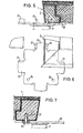
- Fig. 1 die perspektivische Ansicht einer Fußbodenplatte sowie der zugehörigen Doppelbodenstützen,
- Fig. 2 einen Teilquerschnitt durch eine Fußbodenplatte mit L-förmigem Rahmen,
- Fig. 3 einen Teilquerschnitt durch die Fußbodenplatte mit einem L-förmigen Rahmen mit Arretierungsnase;
- Fig. 4 einen Teilquerschnitt durch eine Fußbodenplatte mit einem Rahmen mit nach innen ragenden Stegen,
- Fig. 5 einen Teilquerschnitt durch eine Fußbodenplatte und den Auflageteller einer Doppelbodenstütze mit Arretierungsnasen
- Fig. 6 eine Aufsicht im Teilschnitt auf die Arretierung nach Fig. 5 und
- Fig. 7 einen Teilquerschnitt durch eine Fußbodenplatte mit einer Arretierung durch Stifte.
- 1 is a perspective view of a floor slab and the associated raised floor supports,
- 2 shows a partial cross section through a floor plate with an L-shaped frame,
- Figure 3 is a partial cross section through the floor plate with an L-shaped frame with locking lug.
- 4 shows a partial cross section through a floor plate with a frame with inwardly projecting webs,
- Fig. 5 shows a partial cross section through a floor plate and the support plate of a raised floor support with locking lugs
- Fig. 6 is a plan view in partial section of the locking device according to Fig. 5 and
- Fig. 7 shows a partial cross section through a floor plate with a pin lock.
Wie aus Fig. 1 zu ersehen ist, weist eine entsprechende Fußbodenplatte 1 im allgemeinen quadratischen Querschnitt auf und ist auf 4 Doppelbodenstützen 2 aufgelagert, die im einzelnen dann jeweils aneinanderstoßend die Eckpunkte von 4 derartigen Fußbodenplatten tragen.As can be seen from Fig. 1, a corresponding floor plate 1 has a generally square cross-section and is supported on 4 raised floor supports 2, each of which then supports the corner points of 4 such floor plates in abutting manner.
Die Tragfähigkeit derartiger Platten ist dabei im wesentlichen bedingt durch die Belastbarkeit im Randbereich. Um dabei diese Platten auch für hohe Belastungen im Schwerlastbereich oder im Fahrbereich zu ertüchtigen, ist nach Fig. 2 am Außenumfang der Fußbodenplatte 1 ein lastabtragender Rahmen 3 in Form eines L-förmigen Hohlprofils, z.B. aus Aluminium oder Stahl, vorgesehen, auf dessen nach innen vorspringenden Ansatz 4 eine am Außenumfang entsprechend geformte Trägerplatte 5 aufgelegt ist. Den Rahmen 3 und die Trägerplatte 5 überdeckend, ist auf der Oberseite eine weitere Bodenplatte 6 angeordnet, die über eine lösbare Kleberschicht 7 mit dem Rahmen 3 und der Trägerplatte 5 verbunden ist. Diese Bodenplatte 6 ist zweckmäßigerweise als vorkonfektioniertes Teppichbodenträgerelement ausgebildet und auf ihrer Oberseite bereits mit einem entsprechenden begehbaren Teppichbelag ausgerüstet.The load-bearing capacity of such panels is essentially due to the load-bearing capacity in the edge area. In order to strengthen these panels also for high loads in the heavy load area or in the driving area, a load-bearing
Eine derartige Fußbodenplatte 1 ist somit für höchste Belastungen geeignet und bietet ein Optimum hinsichtlich der Anpassung an die jeweiligen Anforderungen, wobei insbesondere die Materialwahl in weiten Grenzen variiert werden kann. So ist es beispielsweise möglich, aus brandtechnischen Gründen den Rahmen 3 mit einem nicht brennbaren Füllstoff 9, z.B. Gips, auszufüllen. Die Trägerplatte 5 kann aus einer Spanplatte oder einer Gipsfaserplatte oder einem anderen, nicht brennbaren Material gefertigt sein, ebenso wie das Teppichbodenträgerelement 6, das z.B. aus einem Faserzement bestehen kann.Such a floor slab 1 is therefore suitable for the highest loads and offers an optimum in terms of adaptation to the respective requirements, the choice of material in particular being able to be varied within wide limits. For example, for fire-related reasons, it is possible to frame 3 with a non-flammable filler 9, e.g. Plaster to fill out. The carrier plate 5 can be made of a chipboard or a gypsum fiber board or another non-combustible material, as can the
Da die Fußbodenplatte 1 aufgrund ihres stabilen Rahmens 3 keine Kriech- oder Schwindeigenschaften mehr aufweist, besteht auch ein erheblicher Vorteil in der gewählten Ausführungsform darin, daß die Platte sinnvoll teilerneuert werden kann. Hierzu wird der zwischen dem Teppichbodenträgerelement 6 und der Trägerplatte 5 vorgesehene Spezialkleber 7 gelöst und entfernt, so daß dann das Element 6 und/oder die Trägerplatte 5 ausgetauscht und erneuert werden kann. Da darüberhinaus das Teppichbodenträgerelement 6 keine tragende Funktion mehr übernimmt, ist es möglich, darin entsprechende Nutungen 10 vorzunehmen, um evtl. erforderliche Steuerleitungen 11 unterzubringen.Since the floor slab 1 no longer has any creeping or shrinking properties due to its
In Fig. 3 ist ein Rahmen 3 entsprechend Fig. 2 dargestellt, der jedoch zur Verbesserung der Arretierung der Trägerplatte 5 am innenliegenden Ansatz 4 des Rahmens 3 zusätzlich noch eine nach oben ragende Arretierungsnase 12 aufweist.FIG. 3 shows a
Eine weitere zweckmäßige Ausgestaltung eines derartigen Rahmens ist in Fig. 4 dargestellt. Danach besteht der Rahmen aus einem angenähert rechteckigen Hohlprofil 15, der an seiner innenliegenden Ober- und Unterkante je einen nach innen ragenden Steg 16 und 17 aufweist, in den die entsprechende Trägerplatte 5 eingesetzt werden kann.Another expedient embodiment of such a frame is shown in FIG. 4. Thereafter, the frame consists of an approximately rectangular
Zur maßgenauen Festlegung der Fußbodenplatten 1 auf den Doppelbodenstützen 2 sind - wie aus Fig. 5 und 6 zu ersehen ist - im Eckbereich auf der Unterseite des Rahmens 3 Ausnehmungen 20 vorgesehen, in die hochgebogene Stege 21 des Auflagetellers 22 der Doppelbodenstützen 2 hineinragen. Dabei ist aus der Aufsicht nach Fig. 6 die angenähert kreuzförmige Ausbildung des Auflagetellers 22 mit den hochgebogenen Stegen 21 an den kreuzförmigen Ansätzen 23 zu erkennen. Eine derartige Arretierung ermöglicht ein paßgenaues Einsetzen der einzelnen Fußbodenplatten 1, so daß dadurch auf einfache Weise eine Scheibenausbildung der Doppelbodenehene ermöglicht ist.5 and 6, recesses 20 are provided in the corner area on the underside of the
Eine andere Möglichkeit der Festlegung von Fußbodenplatten ergibt sich aus Fig. 7 in Verbindung mit Fig. 6. Wie man aus Fig. 6 ersieht, können in den Eckbereichen der Auflageteller 22 auch Bohrungen 25 vorgesehen sein, in die - wie aus Fig. 7 zu ersehen ist - von unten nach oben herausragende Stifte 26 eingesetzt sind. Diese Stifte 26 ragen dann in entsprechende Löcher 27 im Eckbereich der Fußbodenplatte 1 und gewährleisten damit in gleicher Weise eine sichere Arretierung derselben.Another possibility of fixing floor panels results from FIG. 7 in connection with FIG. 6. As can be seen from FIG. 6,
Insgesamt ergibt sich also eine Fußbodenplatte, die hohe Belastungen aufnehmen kann und die gleichzeitig so aufgebaut ist, daß abgenutzte oder beschädigte Teile leicht ausgewechselt werden können. Durch die darüberhinaus vorgesehene Art der Arretierung der einzelnen Platten ist ein besonders stabiler Aufbau des gesamten Doppelbodens mit Scheibenwirkung gegeben.Overall, this results in a floor plate that can absorb high loads and which is also constructed in such a way that worn or damaged parts can be easily replaced. The type of locking of the individual plates, which is also provided, provides a particularly stable construction of the entire double floor with a pane effect.
Claims (10)
Priority Applications (1)
| Application Number | Priority Date | Filing Date | Title |
|---|---|---|---|
| AT86110122T ATE54705T1 (en) | 1985-07-23 | 1986-07-23 | FLOOR PLATE FOR RAISED FLOORS. |
Applications Claiming Priority (2)
| Application Number | Priority Date | Filing Date | Title |
|---|---|---|---|
| DE19853526300 DE3526300A1 (en) | 1985-07-23 | 1985-07-23 | FLOORING PANEL FOR DOUBLE FLOORS |
| DE3526300 | 1985-07-23 |
Publications (3)
| Publication Number | Publication Date |
|---|---|
| EP0209895A2 true EP0209895A2 (en) | 1987-01-28 |
| EP0209895A3 EP0209895A3 (en) | 1987-09-30 |
| EP0209895B1 EP0209895B1 (en) | 1990-07-18 |
Family
ID=6276513
Family Applications (1)
| Application Number | Title | Priority Date | Filing Date |
|---|---|---|---|
| EP86110122A Expired - Lifetime EP0209895B1 (en) | 1985-07-23 | 1986-07-23 | Floor plates for false floors |
Country Status (3)
| Country | Link |
|---|---|
| EP (1) | EP0209895B1 (en) |
| AT (1) | ATE54705T1 (en) |
| DE (2) | DE3526300A1 (en) |
Cited By (2)
| Publication number | Priority date | Publication date | Assignee | Title |
|---|---|---|---|---|
| EP0295417A2 (en) * | 1987-06-19 | 1988-12-21 | MERO-Werke Dr.-Ing. Max Mengeringhausen GmbH & Co. | Composite building slab, particularly for sectional false floors |
| US20160230404A1 (en) * | 2015-02-05 | 2016-08-11 | Karl Peter Brandstrom | Alignment stopper with adapter and method of use |
Families Citing this family (1)
| Publication number | Priority date | Publication date | Assignee | Title |
|---|---|---|---|---|
| DE3721195C2 (en) * | 1987-06-26 | 1999-02-11 | Rheinhold & Mahla Ag | Raised floor grid system |
Citations (6)
| Publication number | Priority date | Publication date | Assignee | Title |
|---|---|---|---|---|
| FR2213393A1 (en) * | 1972-10-24 | 1974-08-02 | Versino Joseph | |
| FR2236072A2 (en) * | 1973-07-05 | 1975-01-31 | Guy Chenel | Temporary floor of rectangular panels - has gas and electricity fittings in trap doors and feet on panels |
| FR2317445A1 (en) * | 1975-07-10 | 1977-02-04 | Cs Steel Et Cie Sa | Slab for construction of raised floor - is smooth upper panel with ribbed underlying caisson supported on jacks |
| EP0013570A1 (en) * | 1979-01-10 | 1980-07-23 | MARBETON Kies- u. Betonwerk Marstetten GmbH | Elevated flooring system |
| US4279109A (en) * | 1977-05-12 | 1981-07-21 | Madl Jr Joseph | Access floor mounting assembly |
| EP0102211A2 (en) * | 1982-08-26 | 1984-03-07 | Tate Architectural Products, Inc. | Modular tile with positioning means for use with an access floor panel system |
Family Cites Families (2)
| Publication number | Priority date | Publication date | Assignee | Title |
|---|---|---|---|---|
| DE7416234U (en) * | 1974-08-22 | Gruenzweig + Hartmann Und Glasfaser Ag | Base plate for the production of raised floors | |
| DE8110959U1 (en) * | 1981-04-10 | 1981-08-06 | Eisenberg, Hans Jochen, 5600 Wuppertal | KIT FOR BUILDING PODES, STAGE FLOORS, DANCE FLOORS OR THE LIKE. |
-
1985
- 1985-07-23 DE DE19853526300 patent/DE3526300A1/en not_active Ceased
-
1986
- 1986-07-23 AT AT86110122T patent/ATE54705T1/en not_active IP Right Cessation
- 1986-07-23 EP EP86110122A patent/EP0209895B1/en not_active Expired - Lifetime
- 1986-07-23 DE DE8686110122T patent/DE3672707D1/en not_active Expired - Fee Related
Patent Citations (6)
| Publication number | Priority date | Publication date | Assignee | Title |
|---|---|---|---|---|
| FR2213393A1 (en) * | 1972-10-24 | 1974-08-02 | Versino Joseph | |
| FR2236072A2 (en) * | 1973-07-05 | 1975-01-31 | Guy Chenel | Temporary floor of rectangular panels - has gas and electricity fittings in trap doors and feet on panels |
| FR2317445A1 (en) * | 1975-07-10 | 1977-02-04 | Cs Steel Et Cie Sa | Slab for construction of raised floor - is smooth upper panel with ribbed underlying caisson supported on jacks |
| US4279109A (en) * | 1977-05-12 | 1981-07-21 | Madl Jr Joseph | Access floor mounting assembly |
| EP0013570A1 (en) * | 1979-01-10 | 1980-07-23 | MARBETON Kies- u. Betonwerk Marstetten GmbH | Elevated flooring system |
| EP0102211A2 (en) * | 1982-08-26 | 1984-03-07 | Tate Architectural Products, Inc. | Modular tile with positioning means for use with an access floor panel system |
Cited By (3)
| Publication number | Priority date | Publication date | Assignee | Title |
|---|---|---|---|---|
| EP0295417A2 (en) * | 1987-06-19 | 1988-12-21 | MERO-Werke Dr.-Ing. Max Mengeringhausen GmbH & Co. | Composite building slab, particularly for sectional false floors |
| EP0295417A3 (en) * | 1987-06-19 | 1989-05-10 | Mero-Werke Dr.-Ing. Max Mengeringhausen Gmbh & Co. | Composite building slab, particularly for sectional false floors |
| US20160230404A1 (en) * | 2015-02-05 | 2016-08-11 | Karl Peter Brandstrom | Alignment stopper with adapter and method of use |
Also Published As
| Publication number | Publication date |
|---|---|
| EP0209895B1 (en) | 1990-07-18 |
| DE3526300A1 (en) | 1987-02-05 |
| EP0209895A3 (en) | 1987-09-30 |
| ATE54705T1 (en) | 1990-08-15 |
| DE3672707D1 (en) | 1990-08-23 |
Similar Documents
| Publication | Publication Date | Title |
|---|---|---|
| EP0991828A1 (en) | Bridging arrangement | |
| DE4021963A1 (en) | Hollow floor in building - comprises individual plates on height-adjustable supports | |
| EP0285787B1 (en) | Scaffold plank | |
| WO2004018798A2 (en) | Floor made from individual elements | |
| DE4215686C1 (en) | Connection for steel trapezoidal profiles with under construction - is used for roof or ceiling plates formed as concrete-steel union constructions | |
| DE60009330T2 (en) | DEVICE AND METHOD FOR FASTENING A FLAT ELEMENT TO A VEHICLE | |
| EP0180950B1 (en) | Panel-shaped wall element | |
| EP0209895A2 (en) | Floor plates for false floors | |
| EP0062687B1 (en) | Partly prefabricated ribbed floor element | |
| DE1929713U (en) | STATICALLY BEARING PLATE. | |
| DE3801445A1 (en) | Surface-elastic floor element | |
| DE2514036C3 (en) | Structure for houses, halls or the like. Buildings | |
| DE3203314A1 (en) | Roof structure | |
| DE3415848A1 (en) | Rail vehicle | |
| EP0365474A1 (en) | Representative sectional false floor | |
| DE3444666A1 (en) | Box-type board | |
| DE959632C (en) | Warped plank | |
| DE3804311A1 (en) | Large-surface-area panel consisting of ceramic, stoneware, natural stone and/or cast stone | |
| EP0965705B1 (en) | Slab for an elevated floor | |
| DE1946947A1 (en) | Large-capacity container such as a transportable cabin | |
| AT385539B (en) | Double-leaf masonry structure, and building block for such a structure | |
| EP1103672B1 (en) | Parquet from massive wood strips | |
| CH650579A5 (en) | ANGLE PROFILE FOR FINISHING WALL AND FLOOR COVERINGS. | |
| DE2350155C3 (en) | Prefabricated ceiling element made of ceiling plate and knee stick | |
| DE2931963C2 (en) | Multi-storey building made of U-shaped and level construction elements made of concrete |
Legal Events
| Date | Code | Title | Description |
|---|---|---|---|
| PUAI | Public reference made under article 153(3) epc to a published international application that has entered the european phase |
Free format text: ORIGINAL CODE: 0009012 |
|
| AK | Designated contracting states |
Kind code of ref document: A2 Designated state(s): AT DE NL |
|
| PUAL | Search report despatched |
Free format text: ORIGINAL CODE: 0009013 |
|
| AK | Designated contracting states |
Kind code of ref document: A3 Designated state(s): AT DE NL |
|
| 17P | Request for examination filed |
Effective date: 19880329 |
|
| 17Q | First examination report despatched |
Effective date: 19890428 |
|
| GRAA | (expected) grant |
Free format text: ORIGINAL CODE: 0009210 |
|
| AK | Designated contracting states |
Kind code of ref document: B1 Designated state(s): AT DE NL |
|
| REF | Corresponds to: |
Ref document number: 54705 Country of ref document: AT Date of ref document: 19900815 Kind code of ref document: T |
|
| REF | Corresponds to: |
Ref document number: 3672707 Country of ref document: DE Date of ref document: 19900823 |
|
| PLBE | No opposition filed within time limit |
Free format text: ORIGINAL CODE: 0009261 |
|
| STAA | Information on the status of an ep patent application or granted ep patent |
Free format text: STATUS: NO OPPOSITION FILED WITHIN TIME LIMIT |
|
| 26N | No opposition filed | ||
| PGFP | Annual fee paid to national office [announced via postgrant information from national office to epo] |
Ref country code: AT Payment date: 19920527 Year of fee payment: 7 |
|
| PGFP | Annual fee paid to national office [announced via postgrant information from national office to epo] |
Ref country code: DE Payment date: 19920727 Year of fee payment: 7 |
|
| PGFP | Annual fee paid to national office [announced via postgrant information from national office to epo] |
Ref country code: NL Payment date: 19920731 Year of fee payment: 7 |
|
| PG25 | Lapsed in a contracting state [announced via postgrant information from national office to epo] |
Ref country code: AT Effective date: 19930723 |
|
| PG25 | Lapsed in a contracting state [announced via postgrant information from national office to epo] |
Ref country code: NL Effective date: 19940201 |
|
| NLV4 | Nl: lapsed or anulled due to non-payment of the annual fee | ||
| PG25 | Lapsed in a contracting state [announced via postgrant information from national office to epo] |
Ref country code: DE Effective date: 19940401 |