EP0102191A2 - Containerization system, apparatus and method - Google Patents
Containerization system, apparatus and method Download PDFInfo
- Publication number
- EP0102191A2 EP0102191A2 EP83304313A EP83304313A EP0102191A2 EP 0102191 A2 EP0102191 A2 EP 0102191A2 EP 83304313 A EP83304313 A EP 83304313A EP 83304313 A EP83304313 A EP 83304313A EP 0102191 A2 EP0102191 A2 EP 0102191A2
- Authority
- EP
- European Patent Office
- Prior art keywords
- containers
- hatchway
- deck
- hold compartment
- hold
- Prior art date
- Legal status (The legal status is an assumption and is not a legal conclusion. Google has not performed a legal analysis and makes no representation as to the accuracy of the status listed.)
- Granted
Links
- 238000000034 method Methods 0.000 title claims abstract description 18
- 241000251468 Actinopterygii Species 0.000 claims abstract description 105
- 238000003860 storage Methods 0.000 claims abstract description 45
- 230000033001 locomotion Effects 0.000 claims description 54
- 230000007246 mechanism Effects 0.000 claims description 15
- 239000000725 suspension Substances 0.000 claims description 10
- 238000012546 transfer Methods 0.000 claims description 9
- 230000013011 mating Effects 0.000 claims description 7
- 230000008878 coupling Effects 0.000 claims description 5
- 238000010168 coupling process Methods 0.000 claims description 5
- 238000005859 coupling reaction Methods 0.000 claims description 5
- 230000000087 stabilizing effect Effects 0.000 claims description 3
- 238000003780 insertion Methods 0.000 claims description 2
- 230000037431 insertion Effects 0.000 claims description 2
- 239000007788 liquid Substances 0.000 claims description 2
- 230000000452 restraining effect Effects 0.000 claims 3
- 230000037361 pathway Effects 0.000 claims 1
- 239000000969 carrier Substances 0.000 description 8
- 238000010276 construction Methods 0.000 description 8
- 230000004048 modification Effects 0.000 description 4
- 238000012986 modification Methods 0.000 description 4
- 230000010355 oscillation Effects 0.000 description 4
- 230000009467 reduction Effects 0.000 description 4
- 230000000712 assembly Effects 0.000 description 3
- 238000000429 assembly Methods 0.000 description 3
- 238000002844 melting Methods 0.000 description 3
- 230000008018 melting Effects 0.000 description 3
- 238000005192 partition Methods 0.000 description 3
- 230000006641 stabilisation Effects 0.000 description 3
- 238000011105 stabilization Methods 0.000 description 3
- XLYOFNOQVPJJNP-UHFFFAOYSA-N water Substances O XLYOFNOQVPJJNP-UHFFFAOYSA-N 0.000 description 3
- 238000011109 contamination Methods 0.000 description 2
- 238000007599 discharging Methods 0.000 description 2
- 230000000694 effects Effects 0.000 description 2
- 229920001903 high density polyethylene Polymers 0.000 description 2
- 239000004700 high-density polyethylene Substances 0.000 description 2
- 238000012856 packing Methods 0.000 description 2
- 230000000284 resting effect Effects 0.000 description 2
- 238000005096 rolling process Methods 0.000 description 2
- 239000003351 stiffener Substances 0.000 description 2
- 239000004698 Polyethylene Substances 0.000 description 1
- 230000009471 action Effects 0.000 description 1
- XAGFODPZIPBFFR-UHFFFAOYSA-N aluminium Chemical compound [Al] XAGFODPZIPBFFR-UHFFFAOYSA-N 0.000 description 1
- 229910052782 aluminium Inorganic materials 0.000 description 1
- 230000003466 anti-cipated effect Effects 0.000 description 1
- 230000008901 benefit Effects 0.000 description 1
- 239000003638 chemical reducing agent Substances 0.000 description 1
- 125000004122 cyclic group Chemical group 0.000 description 1
- 230000007812 deficiency Effects 0.000 description 1
- 230000006866 deterioration Effects 0.000 description 1
- 238000009432 framing Methods 0.000 description 1
- 239000000295 fuel oil Substances 0.000 description 1
- 230000005484 gravity Effects 0.000 description 1
- 238000009434 installation Methods 0.000 description 1
- 238000009413 insulation Methods 0.000 description 1
- 238000004519 manufacturing process Methods 0.000 description 1
- 239000000463 material Substances 0.000 description 1
- 238000005007 materials handling Methods 0.000 description 1
- 230000002093 peripheral effect Effects 0.000 description 1
- -1 polyethylene Polymers 0.000 description 1
- 229920000573 polyethylene Polymers 0.000 description 1
- 229920002635 polyurethane Polymers 0.000 description 1
- 239000004814 polyurethane Substances 0.000 description 1
- 230000004044 response Effects 0.000 description 1
- 230000000717 retained effect Effects 0.000 description 1
- 238000000926 separation method Methods 0.000 description 1
Images


Classifications
-
- B—PERFORMING OPERATIONS; TRANSPORTING
- B63—SHIPS OR OTHER WATERBORNE VESSELS; RELATED EQUIPMENT
- B63B—SHIPS OR OTHER WATERBORNE VESSELS; EQUIPMENT FOR SHIPPING
- B63B35/00—Vessels or similar floating structures specially adapted for specific purposes and not otherwise provided for
- B63B35/14—Fishing vessels
- B63B35/24—Fish holds
-
- A—HUMAN NECESSITIES
- A01—AGRICULTURE; FORESTRY; ANIMAL HUSBANDRY; HUNTING; TRAPPING; FISHING
- A01K—ANIMAL HUSBANDRY; CARE OF BIRDS, FISHES, INSECTS; FISHING; REARING OR BREEDING ANIMALS, NOT OTHERWISE PROVIDED FOR; NEW BREEDS OF ANIMALS
- A01K63/00—Receptacles for live fish, e.g. aquaria; Terraria
- A01K63/02—Receptacles specially adapted for transporting live fish
-
- B—PERFORMING OPERATIONS; TRANSPORTING
- B65—CONVEYING; PACKING; STORING; HANDLING THIN OR FILAMENTARY MATERIAL
- B65D—CONTAINERS FOR STORAGE OR TRANSPORT OF ARTICLES OR MATERIALS, e.g. BAGS, BARRELS, BOTTLES, BOXES, CANS, CARTONS, CRATES, DRUMS, JARS, TANKS, HOPPERS, FORWARDING CONTAINERS; ACCESSORIES, CLOSURES, OR FITTINGS THEREFOR; PACKAGING ELEMENTS; PACKAGES
- B65D21/00—Nestable, stackable or joinable containers; Containers of variable capacity
- B65D21/02—Containers specially shaped, or provided with fittings or attachments, to facilitate nesting, stacking, or joining together
- B65D21/0209—Containers specially shaped, or provided with fittings or attachments, to facilitate nesting, stacking, or joining together stackable or joined together one-upon-the-other in the upright or upside-down position
Landscapes
- Life Sciences & Earth Sciences (AREA)
- Marine Sciences & Fisheries (AREA)
- Environmental Sciences (AREA)
- Engineering & Computer Science (AREA)
- Mechanical Engineering (AREA)
- Animal Husbandry (AREA)
- Biodiversity & Conservation Biology (AREA)
- Combustion & Propulsion (AREA)
- Chemical & Material Sciences (AREA)
- Ocean & Marine Engineering (AREA)
- Ship Loading And Unloading (AREA)
- Packging For Living Organisms, Food Or Medicinal Products That Are Sensitive To Environmental Conditiond (AREA)
- Packages (AREA)
- Stackable Containers (AREA)
- Supplying Of Containers To The Packaging Station (AREA)
- Container Filling Or Packaging Operations (AREA)
Abstract
Description
- This application is a continuation-in-part of U.S. patent application Serial No. 402,111 filed 26 July 1982.
- This invention relates to method and apparatus for the transfer of objects, closely packed within an enclosure, between the interior of the enclosure and selected positions on the top deck of the enclosure. More particularly, the invention relates to method and apparatus for transferring containers for the storage of fish in the hold of a vessel between the hold and the deck through a hatchway in the deck. The invention also relates to suitable such nesting containers, and to the containerized fish handling system comprising the containers, the transferring apparatus, and support and guiding structures within the hold of the vessel.
- Known methods of holding fish onboard trawlers and discharging them from the hold are subject to a number of disadvantages.
- One such method comprises the storage of fish below )deck in large pens. Such pens are typically assembled during fishing operations by the fitting of corrugated aluminum boards (pen boards and shelving boards) into vertical stanchions permanently installed in the hold.. Fish are subsequently removed by breaking down the pen boards and shelving and directing the loose fish to a conveyor system, air unloader or other impelling device to remove them from the hold. Storage of fish in pens utilizes space in the hold efficiently, but results in a deterioration of quality in the fish, arising in part from the considerable weight exerted on fish near the bottom of the pen by those above, and in part from physical damage that occurs during discharging.
- Another method, which leads to the delivery to port of fish of a very high quality, employs the boxing of fish and ice in relatively small boxes (approximately 100 lb. capacity) and storage of such boxes by stacking them within the hold. However, boxing entails a high labour cost and the boxes employed and the manual procedures employed in their handling are volumetrically inefficient. Furthermore, neither boxing nor holding in pens lends itself to high rates of unloading fish from the hold.
- Apparatus for handling fish containers to be stowed within the hold of a ship is disclosed in United States Patent 2,448,373 (Hurst), which describes the gravity-controlled swinging of containers lowered into the hatchway towards either side of the hold by means of a system of ropes and pulleys. However, this system is not adapted to the rapid and volumetrically efficient storage and removal of the large number of relatively small, rigid containers required to ensure delivery of high quality fish to shore.
- In accordance with the present invention, there is provided a system of containerized fish handling which overcomes the deficiencies of prior systems of handling fish on board an ocean going vessel. This system allows the storage of fish in containers of sufficiently small interior depth to ensure delivery to port of a high quality product, while at the same time achieving high volumetric efficiency of fish storage within a hold compartment of a fishing vessel and high rates of discharge of containers from or transfer to a hold compartment.
- According to the containerized fish handling system of the present invention, fish are stored in each hold compartment of the vessel in closely stacking, vertically mating containers. Each container is provided with extended side walls between which nests the container arranged immediately above it. The side walls of each container are provided with apertures or other suitable gripping sites adapted to be engaged from above by gripping means positioned over the container and between the extended side walls, thereby allowing containers to be removed from the hold compartment and yet be stacked close together therein, so that the maximum storage capacity of the hold compartment for containers may be utilized.
- The rapid and efficient transfer of containers between storage positions in the hold compartment and working positions above the deck overlying the hold of the vessel is achieved by the use of an in-hold travelling hoist to move a plurality of containers to and from selected positions within the hold compartment in co-operation with an above-deZk conveying system, including an above-deck hoist, operable to convey the plurality of containers between a position interior of the hold compartment directly below an open hatchway in the deck and a selected working position on the deck. Each hoist is provided with a vertically movable lifting frame having extendible projections adapted for engagement with or release from the gripping sites of a plurality of containers arranged end-to-end in a horizontal row, so that a row of containers may be thereby lifted from the next underlying row without disturbing the containers stacked in rows adjacent to the sides or bottom of the row being lifted.
- Transporter assemblies which utilize the principle of horizontal movement of a lifting device on a track and of hoisting and lowering therefrom for the purpose of lifting cargo from within a hold of a ship to dockside and vice versa are known in the art of materials handling, as in United States Patent 2,591,140 (Dougherty), United States Patent 3,543,952 (Young), United States Patent 3,630,390 (Tax), United States Patent 3,881,608 (Hupkes) and United States Patent 3,946,881 (Ludvigsen). Travelling crane assemblies which further provide for fore-and-aft motion of the entire lifting unit are also known for use with container ships, as in United States Patent No. 2,456,104 (Andersen), United States Patent No. 2,984,367 (McIntyre) and United States Patent No. 4,049,132 (Stromback).
- The apparatus of the present invention differs from the prior art relating to marine transporter assemblies in disclosing a travelling hoist which operates beneath a deck of a fishing trawler at sea in co-operation with above-deck conveying apparatus in an efficient system for the transfer of containers suitable for the storage of fish between a working deck and selected locations in the hold.
- Stackable, vertically interlocking packing or transport cases for the storage or transportation of fish in an ice-packed condition, which provide for outside drainage of melt water to prevent contamination of the contents of the lower container in a stack, are known. Examples of such containers are disclosed in United States Patent 3,338,468 (Wilson), United States Patent 3,366,273 (Crocella et al.) and United States Patent 3,447,716 (Nesse). Cases of this type are not, however, provided with extended, slotted side walls to impart transverse strength to a stack of nesting containers while allowing for grasping and lifting of a container by a mechanism operating between the side walls. Interior gripping ability allows an array of such containers to be lifted without disturbing adjacent containers. Higher stacking strength may be achieved by exterior vertical corrugations in the side walls of the container, which is further rigidified by a stiffener rod fastened between the side walls. The stiffener rod also provides support for a cover that fits closely between the side walls and curves over the end walls of the container in a frictional fit.
- Directed generally to a method, apparatus and system for the efficient storage of objects within an enclosed space and their cyclical removal and replacement within that space, and particularly to the containerization and handling of fish on board an ocean-going vessel, the invention, in one aspect relates to & nesting container having a bottom wall, a pair of side walls extending upwardly from opposite sides of the bottom wall and a pair of end walls extending upwardly from opposite ends of the bottom wall, the container being configured and dimensioned at its top and bottom for mating engagement with the bottom and top, respectively, of similar vertically adjacent containers in a vertical stack. The side walls are provided with gripping sites in the vicinity of the upper portions thereof, adapted to be engaged by gripping means operating between the side walls, thereby allowing containers to be lifted without disturbing like containers stacked closely at the sides and ends of the container being lifted.
- Another aspect of the invention is a nesting container for the storage of fish and ice within the hold of a fishing vessel, wherein the bottom portions of the side walls are inwardly recessed a sufficient amount that the bottom portion of such containers is of a reduced width dimensioned to be received between the extending upper portions of the side walls of a similar container stacked vertically therebelow. The vertical dimension of the bottom portion of the container of reduced width is slightly less than the vertical dimension of the upper portion of the side walls extending beyond the tops of the end walls. One of the vertical end walls has a drainage hole therethrough located immediately above the interior face of the bottom wall, to allow drainage of melting ice, and the container is further provided with an arrangement of parallel drainage grooves running vertically along the interior faces of the end walls and longitudinally along the interior face of the bottom wall to communicate with the drainage hole, so that liquid in the container flows along the drainage grooves and out the drainage hole.
- It is a further aspect of this invention to provide apparatus for the transferring of objects between storage positions in the interior of an enclosure covered by a top deck having an opening therethrough narrower than the dimensions of the enclosure and at least one selected position on the top deck. The apparatus comprises in combination internal hoisting means disposed below the top deck of the enclosure, operable to convey the objects between a location directly below the opening and other locations within the enclosure, and external O conveying means disposed above the top deck of the enclosure operable to.convey the objects between the location within the enclosure directly below the opening and at least one position on the top deck of the enclosure.
- In a further aspect of the invention for use aboard a :5fishing vessel having a hold compartment provided with a hatchway through the main deck overlying the hold compartment, apparatus is provided for transferring fish containers between storage positions in the hold compartment and at least one working position above the hold compartment. The apparatus comprises internal hoisting means disposed below the main deck of the hold compartment, operable to convey fish containers between a location directly below the hatchway and other storage positions within the hold compartment, and external conveying means disposed above the main deck of the hold compartment operable to convey the fish containers between a location within the hold compartment directly below the hatchway and at least one working position above the hold compartment.
- In another of its aspects, the subject invention is a system for the containerization and handling of fish aboard a fishing vessel having a main deck, at least one hold compartment beneath the main deck and a longitudinal hatchway through the main deck extending in length over substantially the full length of the hold compartment. The system comprises in combination a plurality of similar stackable fish containers, each provided with cover means and having matching opposed flanges extending upwardly at opposite sides of the cover means, and further having a bottom portion configured for nesting engagement with the top flanges of a similar container stacked therebelow, the flanges being further provided with opposed gripping sites adapted for engagement by gripping means positioned over the cover means and between the two opposed flanges, whereby the top container of a stack of containers may be vertically lifted from the stack without disturbing containers in adjacent stacks, hoisting means disposed below the main deck and operable to selectively grip and release containers at their gripping sites and to convey them between selected positions within the hold compartment, and conveying means disposed above the main deck operable to selectively grip and release containers and to convey them between a location within the hold compartment directly below the hatchway and at least one working position on the main deck of the fishing vessel.
- The invention in another of its aspects is a system for the containerization and handling of fish aboard a fishing vessel having a main deck, at least one hold compartment beneath the main deck and a longitudinal opening through the main deck extending in length over substantially the full length of the hold compartment, which comprises in combination, a plurality of similar stackable fish containers provided with cover means and matching flanges extending upwardly from each such container at opposite sides of the cover means, each such container being provided with opposed gripping sites adapted for engagement by gripping means positioned over the cover means between the two opposed flanges, the containers being configured and dimensioned for vertical mating engagement in a predetermined array of vertical stacks in close lateral contact within the hold compartment, each layer of any such vertical stacks comprising a predetermined number of such stackable containers in a longitudinal row, first hoisting means disposed below the main deck, operable to grip a single longitudinal row of containers positioned within the hold compartment, to raise or lower the row of containers and to transport the row of containers between selected positions within the hold compartment, the first hoisting means being operable to grip a single longitudinal row of containers positioned within the hold compartment, to raise or lower the row of containers and to transport the row of containers between selected positions within the hold compartment, including a position directly beneath and in alignment with the longitudinal opening through the main deck, and including a lifting frame vertically movable between the vicinity of the underside of the main deck and locations vertically spaced therebelow and horizontally movable between locations within the hold compartment when in the vicinity of the underside of the main deck, said lifting frame being dimensioned for placement between the opposed side flanges of a longitudinal row of containers, and gripping means mounted to said first lifting frame and operable to selectively engage and release the gripping sites of the containers in said longitudinal row, an array of vertical guide members transversely spaced along each end of the hold compartment and adapted to prevent undesired horizontal movement of the rows of containers, while permitting vertical movement of the rows of containers and permitting horizontal movement of the rows of containers when said rows have been raised to a location proximate the underside of the deck, and conveying means disposed above the main deck and operable to selectively grip and release a single longitudinal row of containers and to convey that row between a location within the hold compartment directly below the longitudinal opening and at least one working position on the main deck of the fishing vessel.
- In a preferred embodiment of a system for the containerization and handling of fish aboard a fishing vessel according to the present invention, the conveying means disposed above the main deck includes stationary hoist means fixedly mounted over the hold compartment and operable to raise and lower a row of containers between a position within the hold compartment directly beneath the longitudinal opening through the main deck and a position above the main deck, the stationary hoist means including an upper hoist vertically spaced from the main deck and fixedly mounted thereabove, a second lifting frame, suspension means suspending the second lifting frame from the upper hoist, a power mechanism operatively connected to the suspension means for raising and lowering the second lifting frame, the second lifting frame having a plurality of vertical frame guides extending upwardly from the perimeter thereof, said vertical frame guides being operable to assist in stabilizing said second lifting frame when it is raised to a maximum elevation by the power mechanism, gripping means mounted to the second lifting frame and operable to selectively engage and release the gripping sites of the containers in a longitudinal row, movable object support means associated with the opening through the main deck, movable between an open configuration which permits a row of containers to pass through the opening, and a closed configuration in which the support means is operable to support a row of containers above the opening. In this preferred embodiment, the stationary hoist means also includes roller conveyor means operable to support containers being moved between a working position directly over the hold compartment and other locations on the main deck, and an array of second vertical guide members extending upwardly from the opening through the main deck toward the upper hoist associated therewith, the second vertical guide members being adapted to slidably engage the vertical frame guides of the associated lifting frame to prevent undesired horizontal movement of that lifting frame, while permitting its vertical movement.
- Advantageously, the movable object support means associated with each opening through the main deck may also comprise roller-topped members so arranged that the roller-topped members and the roller conveyor means form a continuous track operable to support objects moved therealong when the movable object support means is in its closed configuration.
- The invention is also, in another of its aspects, a method for charging containers*with fish and ice and stowihg them in a vessel equipped with a system of stackable fish containers, first hoisting means, vertical guide members and conveying means, comprising the steps of transferring rows of containers, empty of fish, from the hold compartment to a working position, charging them with fish and ice, returning them to the hold compartment, and restacking them therein, by use of the conveying means and first hoisting means, proceeding row by row and stack by stack in a cyclical series of operations, without moving charged containers after they have been restacked in the hold compartment.
- The detailed description is separated into descriptions of original embodiments of the apparatus, presently preferred embodiments of the apparatus, and the operation of a fishing trawler provided with alternative embodiments of hoisting apparatus used in the trawler containerization system of the invention.
- In the drawings which illustrate embodiments of the invention, and in which like reference numberals refer to like structural components throughout,
- FIGURE 1 is an end elevational sectional view of a fish container for use in the containerization system of the present invention.
- FIGURE 2 is a side elevational sectional view of the container of Figure 1, including a snap-on cover and horizontal grooves in the end walls for securing the cover.
- FIGURE 3 is a perspective view from above and to one side of the container of Figure 1, without a cover.
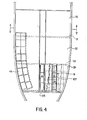
- FIGURE 4 is a top plan view, partly broken away, of the factory deck of a fishing trawler equipped with a containerization system according to the present invention.
- FIGURES 5a to 5d are cross-sectional views through a hold compartment along the line V-V of Figure 4, showing the disposition of containers at various stages of the handling operation and further showing the co-operating hoist systems.
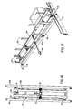
- FIGURE 6 is a top plan view of the travelling framework of an in-hold transverse travelling hoist mounted for travel along transverse beams affixed to the underside of the working deck of a fish hold compartment.
- FIGURE 6a is a partial perspective view of a presently preferred embodiment of internal hoisting means for use within a fish hold compartment.
- FIGURE 6b is a partial perspective view of the interior of a fish hold compartment showing the manner of installation of the internal hoisting means of Figure 6a for transverse movement along the underside of the working deck.
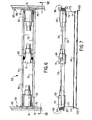
- FIGURE 7 is a side elevation view of the travelling framework of Figure 6 seen along the section VII-VII showing the lifting frame suspended from the travelling framework.
- FIGURE 8 is an enlarged partial top plan view of the travelling framework of Figure 6 showing in dotted outline the mechanism of engagement of one end pair of framework rollers with the corresponding transverse track.
- FIGURE 9 is a side elevation view of the portion of the travelling framework shown in Figure 8.
- FIGURE 10 is an end elevational view of Figure 8 along the section X-X, partly broken away to reveal the mechanism of engagement of one end pair of framework rollers with the corresponding transverse track.
- FIGURE 11 is an enlarged fragmentary view of a lifting frame such as that associated with either the in-hold transverse travelling hoist of Figure 7 or the above-deck longitudinal travelling hoist of Figure 16.
- FIGURE lla is a fragmentary perspective view of a preferred embodiment of lifting frame for use with the internal hoisting means.
- FIGURE 12 is a cross-sectional view along the section XII-XII through the lifting frame of Figure 11.
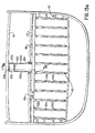
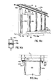
- FIGURE 13 is a transverse vertical sectional view of a typical hold compartment empty of containers according to an original embodiment of the invention.
- FIGURE 13a is a transverse vertical sectional view of a typical hold compartment fitted with a presently preferred arrangement of below and above-deck restraint devices.
- FIGURE 13b is an expanded cross-sectional view along the section XIII-XIII of Figure 13a.
- FIGURE 14 is a partial perspective view of the hold compartment of Figure 13, showing the vertical guide members located along one end of the hold compartment and a transverse beam for supporting the travelling framework of Figure 6.
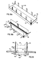
- FIGURE 14a is a partial perspective view of the hold compartment of Figure 13a, showing the presently preferred vertical guide members located along one end of a hold compartment and the bottom container supports.
- FIGURE l4b is a cross-sectional view along the section XIVb-XIVb of Figure 14a.
- FIGURE 14c is a partial plan view of a typical hold compartment showing an alternative preferred construction of guides and restraints.
- FIGURE 15 is a fragmentary side elevational view of an in-hold transverse travelling hoist with lifting frame engaging a container at the top extent of its vertical travel within a hold compartment having the original arrangement of below-deck restraints illustrated in Figure 14.
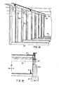
- FIGURE 15a is a fragmentary side elevational view of an in-hold transverse travelling hoist with lifting-frame engaging a container at the top extent of its vertical travel within a hold compartment, indicating the operation of a presently preferred construction and arrangement of below and above-deck restraint devices depicted in Figure 14b.
- FIGURE 16 is a top plan view of the travelling framework of the above-deck longitudinal travelling hoist mounted for travel along longitudinal tracks affixed to the underside of the upper deck of a fishing trawler.
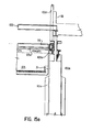
- FIGURE 16a is a side elevation view of one of the above-deck stationary hoists used in a presently preferred embodiment showing the upper lifting frame suspended from the upper bridge hoist.
- FIGURE 16b is a fragmentary perspective view of a preferred embodiment of upper lifting frame for use with the above-deck stationary hoist of Figure 16a.
- FIGURE 17 is a perspective view of a transverse moving framework mounted on the factory deck in the vicinity of the hatchway through the deck.
- FIGURE 18a is a perspective view of an outwardly opening hinged hatch cover with vertically extending container side restraints which may be used as an alternative to the transverse moving framework of Figure 17.
- FIGURE 18b is a perspective view of the hatch cover of Figure 13a showing the hatch cover in the open position.
- FIGURE 19 is a cross sectional view through the factory deck of an outwardly opening hinged hatch cover and movable container support means which may be used as an alternative to the transverse moving framework of Figure 17.
- FIGURE 19a is a transverse cross-sectional view through the factory deck of an outwardly opening hinged hatch cover including movable container support means provided with roller means for longitudinal conveyance of containers from one hold compartment to another.
- FIGURE 19b is a partial cross-sectional view along the length of a continuous hatchway of a trawler showing a preferred embodiment of roller conveyor means for longitudinal conveyance of containers from one hold compartment to another.
- A nesting container for use in the storage and handling of fish on a fishing trawler using the method and apparatus of the present invention is illustrated in Figures 1 to 3.
- Such a container is preferably of double-wall construction and fabricated of high density polyethylene or other high strength material suitable for contact with foodstuffs. Polyurethane insulation may be foamed into place within the double walls during fabrication to further rigidify the structure and to reduce the melting of ice packed with fish into the container.
- The vertical stacking strength of the containers is enhanced by the inclusion of a series of exterior vertical corrugations 1 formed in
side walls 3 and endwalls 5, as best seen in Figure 3.Bottom wall 4 is strengthened by a series of exteriorhorizontal corrugations 6, seen in cross-section in Figure 2. - The upper portions--7 of the
side walls 3 extend vertically beyond thetops 9 of theend walls 5. The bottom portions 11 of theside walls 3 are inwardly recessed a sufficient amount that the bottom portion of the container is of a reduced width dimensioned to be received between the extendingupper portions 7 of theside wall 3 of a similar container container stacked vertically therebelow. - Preferably, the vertical dimension of the bottom portion of the container of reduced width is slightly less than the vertical dimension of the
upper portions 7 of theside walls 3 extending beyond thetops 9 of saidend walls 5 to allow for the thickness of container covers, described below, in the stacking of containers one above the other. For ease of nesting and separation of containers stacked one above the other, the recessed bottom portions 11 of theside walls 3 are preferably sloped slightly outwardly from the bottom as seen in Figure 1. - Through each of side wall
upper portions 7 there is a pair oflongitudinal slots 13 opposed to a corresponding pair of slots in the opposite side wall portion. As will be described in more detail below with reference to the hoisting systems of the present invention, these slots through extended side wall portions impart to a container the ability to be lifted from the top of a stack of such containers without disturbing like adjacent containers disposed below, to either side or to either end of the container being lifted. - Added strength along the parallel side wall portions extending above the upper edges of the end walls is achieved by the inclusion of an
elongate stiffening member 15 fastened at opposed locations on the interior surfaces of the side walls so that the top surface ofmember 15 lies in a horizontal plane with theupper edges 9 of the end walls of the container.Member 15 is preferably a polyethylene pipe cross member welded at each end to opposite locations on the interior faces ofside walls 3. Each container is provided with acover 17 dimensioned for close fit between theextended portions 7 of the parallel side walls. As best seen in Figure 2, the cover is supported at its ends by the upper edges of the end walls, and centrally by the stiffening member.Cover 17 is provided withend tabs 19, which turn down over the end walls of the container in a snap fit inhorizontal grooves 21 in the exterior faces ofend walls 5.Cover 17 may simply be a sheet of high density polyethylene of sufficient thickness and strength to retain the contents of fish and ice during rolling motion of the trawler at sea. The cover also serves to prevent contamination of the contents of a container. - Each container is provided with a
drainage hole 23 through one of theend walls 5 to allow water formed by the melting of ice within a container to drain along the outside of the end walls of containers stacked below. The bore ofhole 23 is screw-threaded to allow insertion of a threadeddrainage plug 25. Melt water within a container is internally drained towardsdrainage hole 23 along an arrangement ofparallel drainage grooves 27 running vertically along the interior faces ofend walls 5 and longitudinally along the interior face ofbottom wall 4 to communicate withdrainage hole 23. - As shown in Figure 5c, at various times'during the operation of the system, as hereinafter described in detail, there will be empty space between two vertical stacks of containers. The end containers of each row are retained against undesired lateral movement by engagement with vertical T-section members, also hereinafter described in detail. To prevent dislodgement by motion of the ship of the interior containers of a row adjacent to the vacated space, at least the containers constituting each row of the second layer from the top of a hold compartment are secured together by removable connecting means which may be released when such a row of containers is placed on deck for loading with fish and ice. The connecting means used may comprise channel connectors adapted to be snapped over adjacent extended side wall portions of containers within the longitudinal row, or a removable dowel rod inserted through a longitudinal channel extending through matching openings in the extended side wall portions of the containers in the row, or any other convenient connecting means. In Figure 1,
side wall portions 7 are shown as provided withlongitudinal holes 29, to accommodate securing dowel rods. - To facilitate the entry of the container between the T-section members described below when the container is being lowered into position, the
side walls 3 of the container are preferably provided with taperedguide portions 31, as best seen in Figure 3. - In accordance with the present invention, a trawler fish hold is divided across its length into a plurality of fish hold compartments (three or four, depending on the overall length of the hold). As shown in Figure 4,
partitions compartments - A cross-sectional view across
hold compartment 35 is shown in Figure 5a, illustrating theupper deck 41 which lies spaced above the main orfactory deck 43. A plurality of identical nesting containers is shown stacked withinhold compartment 35. Containers stacked within a hold compartment are arranged in longitudinal rows each containing a predetermined number of containers that depends upon the relative length of the hold compartment and a container. - As will be described in more detail below, according to the working of the present invention, the largest hold compartment is not entirely filled with containers when the trawler leaves port. Rather, as seen in Figure 4, the topmost layer of containers for that hold compartment is stored above the deck of the vessel in a
container storage system 49, which is preferably located above the working decks of the smaller hold compartments disposed toward the fore of the vessel. The vacant top layer space over the remaining containers within the largest hold compartment enables the temporary storage of all the rows of containers from any vertical stack, within this top layer space, preparatory to their removal to the above-deck charging area. In the preferred embodiment, the number of rows which can be accommodated across the top layer is sufficiently great relative to the number of rows comprising any vertical stack to permit storage of all the rows of the vertical stack in the vacant top layer space below and to one side of the hatchway. - For the moving and placement of containers located beneath the factory deck, each hold compartment is provided with internal hoisting means disposed below the factory deck and operable to convey fish containers between a location directly below the hatchway and other storage positions within the hold compartment. In the original embodiment, the internal hoisting means is a transverse travelling hoist, which is described below with reference to Figures 4, 6, 7, 8, 9, 10, 11, 12 and 13.
- In Figure 4, the transverse travelling hoist associated with
hold compartment 39 is indicated at 51. The transverse travelling hoist associated withhold compartment 35 is indicated at 53 in Figure 5a, engaging and suspending a longitudinal row of containers 55. - The structure of in-hold transverse travelling hoist 53 is shown in detail in Figures 6, 7, 8, 9, 10, 11, 12 and 13. As best seen in Figures 6, 7, 8, 9 and 10, hoist 53 comprises a rectangular travelling
framework 56, having fouridle rollers 57 mounted at its four corners for travel along a pair oftransverse tracks 58 affixed to the underside of workingdeck 43 along opposite ends ofhold compartment 35. -
Framework 56 carries two similar motor andgear reducer combinations 59 each operatively connected to a circulartoothed pinion 61 which engages the teeth of ; correspondingrack section 63.Rack sections 63 are affixed to oppositetransverse tracks 58. - Motion of
framework 56 alongtracks 58 in either transverse direction, and its placement at a selected lateral position along the underside of the working deck, may be effected by actuating, stopping or reversing the motor/reduction gear combinations 59. - Transverse travelling hoist 53 also comprises a
rectangular lifting frame 65, shown in side elevational view in Figure 7, suspended below travellingframework 56. - Lifting
frame 65 is adapted to engage a longitudinal row of containers running the length of a hold compartment. Vertical travel offrame 65 is effected by means of a four-drum winch 69 mounted on transverse travellingframework 56 and powered by a third motor/reduction gear combination 71 centrally mounted onframework 56. The rotation ofwinch 69 extends or retractscables 73 which are looped over fourpulleys 75 disposed towards the four corners of framework 55 and attached by any convenient means to corresponding corners of liftingframe 65, as shown at 77 in Figure 7. Whencables 73 are retracted so that liftingframe 65 is at its maximum elevation, lateral oscillations offrame 65 are prevented by the abutting proximity offrame 65 to travellingframework 56. - Details of the container pick-up means with which lifting
frame 65 is provided are shown in Figures 11 and 12. Liftingframe 65 includes opposed pairs of container-engaging lugs projecting frommembers 77 pivotally mounted onpins 79 along the long sides offrame 65. Each lug presents acontainer engaging portion 81 which projects outwardly beyond the long side offrame 65 at one extreme of the pivotal movement of themember 77, to permit engagement with amatching slot 83 through the side wall of a container. In Figure 12, the container-engaging lugs are shown in the engaged position. - Each lug-carrying
member 77 comprises a lever portion 84 extending towards the interior of liftingframe 65. By exertion of a longitudinal force against lever portions 84, it may be seen.that the container-engaging lugs can be extended to engage, or retracted to disengage withslots 83 in thecontainers 85 and 86. The two pairs of matching opposed lugs nearest end 87 of liftingframe 65 in Figure 11, correspond to the four slots through the extended side walls of asingle container 85. Container 86 next adjacent the end ofcontainer 85 in the longitudinal row of containers is likewise engaged through its four slots by the next four lugs, etc. - Only the linkages involved in engaging the first container in a longitudinal row are completely shown, as the pattern of lugs and the manner in which they are linked repeats over the length of lifting
frame 65. The length of the frame and hence the number of quartets of lugs positioned to engage a single container will depend upon the length of the particular hold compartment and the number of containers placed end-to-end in a longitudinal row accommodated by that hold compartment. - The simultaneous engagement or disengagement of all the lugs from the row of containers between whose
extended side 5walls lifting frame 65 is positioned is effected by the action of apneumatic cylinder 88 andpiston 89 combination powered by an air compressor and air receiver unit (not shown) carried onframe 65.Piston 89 is pivotally linked to cross member 91 which is adapted to pivot about a centrally locatedpin 93 in response to longitudinal movement ofpiston 89. All container-engaging lugs along either side offrame 65 are constrained to move in unison by pivotal connections of the lever portions 84 of the associated members with alongitudinal coupling member 95 linked to pivoting cross member 91 at opposite ends thereof by pins 97.Pins 97 are situated within slots 96 in the ends of pivoting member 91, thereby allowing for the slight transverse movement of cross member 91. - As viewed in Figure 11, retraction of
piston 89 causes cross member 91 to move in the sense indicated byarrow 98, thereby movingcoupling members 95 in opposite longitudinal directions, as indicated by arrows 98a and 98b, and moving the container-engaging lugs to the retracted (disengaged) position. Extension ofpiston 89 causes the lugs to extend and engageslots 83 incontainer 85. - A
spring 99 connects couplingmember 95 to the end 87 offrame 65 to exert a biasing force on the lugs toward the engaged position. In the event of an accidental loss of power toair cylinder 88 when liftingframe 65 is carrying a row of containers,spring 99 maintains the lugs in the engaged position and the undesired release of the containers is averted. It will be understood that other linear actuator means than the above-described pneumatic cylinder and piston combination could be employed to effect the desired engagement or disengagement of the lugs. - The removal of containers from and their replacement into a hold compartment of a fishing trawler at sea requires restraint devices within the hold to ensure that containers will not be thrown into unfilled spaces or damaged by lateral swinging of the suspended lifting frame on the in-hold travelling hoist in the event of rolling of the vessel. The original embodiment of these restraint devices is described below with reference to Figures 13, 14 and 15.
- As seen in Figures 13 and 14, the partition between . adjacent hold compartments comprises an arrangement of parallel guides and supports extending from the bottom of the hold up to the main beam beneath the factory deck. Figures 13 and 14 provide a sectional view and a perspective view, respectively, of a typical hold compartment, empty of containers so that the alternating set of vertical channel guides 100 and T-
section members 101 may be seen. A hold compartment is bounded at its front and back ends by two such sets of opposed channel guides and T-section members. As may best be seen in Figure 14, eachchannel guide 100 and each T-section member 101 is associated with a flatvertical partition portion 102 extending from thefloor 44 of the hold compartment upwardly to meet thetransverse track 58 mounted against the underside ofmain deck 43. - As shown in Figures 14 and 15, the vertical extent of the channel guides 100 and T-
sections 101 is such that liftingframe 65 is restricted to vertical movement, except when raised to the top extent of its travel, by the engagement of projectingmembers 103, centrally located at either end of liftingframe 65, within the vertical channel ofchannel end guide 100. When raised to the top limit of its travel, liftingframe 65 is in close proximity to the travellingframework 56, and so restrained against lateral oscillation with respect to travellingframework 56. - As may be seen from Figure 15,
container 104, a container at the end of a longitudinal row of containers engaged by liftingframe 65, is itself restrained from transverse movement when positioned below its highest point of vertical travel within the hold by the two vertical T-section guides 101 located at either side ofcontainer 104. - In ordinary use in the container-handling method of the present invention, a below-deck transverse travelling hoist is moved across a hold compartment only when the lifting
frame 65 is drawn up against transverse travellingframe 56. In this retracted position the row of containers engaged by the lifting frame and the lifting frame itself are clear of the lateral restraints presented by the vertical channel guide and T-section members, but are sterilized by proximity to the - travelling frame and the transverse tracks along which it moves. Whenever the lifting frame is lowered vertically into the hold, however, accidental lateral swinging movement of the frame and engaged containers is prevented by the arrangement of vertical guides described above. - As seen in Figures 4 and 5a, each hold compartment presents a
longitudinal hatchway 105 through workingdeck 43 overlying the hold compartment.Hatchway 105 is centrally disposed over the predetermined storage location of one vertical stack ofcontainers 106, so that the uppermost longitudinal row of containers ofstack 106 may be vertically lifted from the interior of the hold compartment throughhatchway 105 to a position directly above the hatchway. - Conveying means external to the hold compartment are operable to convey fish containers between a location within the hold compartment directly below the hatchway and at least one working position on the main deck of the hold compartment. In one embodiment of the invention, the above-deck components of the container handling apparatus of the present invention, which effect the raising and lowering of a longitudinal row of containers positioned within a hold compartment directly below the hatchway of that hold compartment and the transportation of the row of containers to and from selected locations on the working deck, include a longitudinal travelling hoist.
- As seen in Figure 5a, longitudinal travelling hoist 107 is mounted next to the underside of
upper deck 43 on parallellongitudinal tracks 108 straddlinghatchway 105. - An enlarged top plan view of above-deck longitudinal travelling hoist 107 is shown in Figure 16. Travelling hoist 107 includes a rectangular travelling
framework 109, having fouridle rollers 110 mounted at its four corners for travel alongtracks 108. Travellingframework 109 is powered to move alongtracks 108 by means such as a motor drive and reduction gear combination 111, the drive shaft llla of which is linked at its ends to rack-and-pinion drive mechanisms similar to that of transverse travellingframework 56, described above. - Longitudinal travelling hoist 107 also includes a rectangular lifting frame and gripping means of like construction to
rectangular lifting frame 65, described in connection with Figure 11. Vertical travel of the lifting frame associated with longitudinal travelling hoist 107 is effected by means of a four-drum winch 112 mounted on longitudinal travellingframework 109 and powered by a motor/reduction gear combination 113, in a manner similar to the lifting mechanism described in relation to the below-deck transverse travelling hoist described above. - Travelling hoist 107 may be positioned over the hatchway of each successive hold compartment to move a longitudinal row of containers therefrom or to deposit a row of containers vertically into the hold compartment directly below the hatchway, whence it may be engaged and transported laterally to selected positions within the hold by the in-hold transverse travelling hoist 5E,
- At least one hold compartment is provided with travelling support means, operable to convey containers between a location above the main deck directly over the hatchway and a working position to one side of the hatchway. In one embodiment, the placement on the working area of the factory deck of a row of containers is effected by providing at least one hold compartment with an above-deck transverse moving
frame unit 114 which acts in co-operation with above-deck longitudinal travelling hoist 107. As shown in Figure 17, transverse movingframe 114 is provided at its four corners withrollers 115 mounted for movement along paralleltransverse segments 116, wherebyframe 114 may be positioned by suitable drive means such ashydraulic drive 117 for lateral positioning of the framework directly overhatchway 105 or displaced fromhatchway 105 toward a separate container storage and fish loading area on the factory deck. In Figure 17,frame 114 is shown positioned over thehatch coaming 118 defining the opening ofhatchway 105.Frame 114 is provided around its periphery with spacedvertical members 119 to guide containers into the frame and to provide lateral support. - When a row of containers has been lifted from within a hold compartment by travelling hoist 107, transverse moving
frame 114 may be positioned overhatchway 105 directly beneath the row of containers held by the above-deck travelling hoist. The containers may then be lowered intoframe 114 onto supportingplatform portion 120, in the position shown in broken lines in Figure 17, for transverse movement into positon for filling with fish and ice. By reversing this operation, a row of containers so filled may be replaced into the hold compartment. - Alternatively, a row of containers lifted from within a hold compartment and lowered into
frame 114 positioned directly overhatchway 105 may be filled with fish and ice while held inframe 114 directly overhatchway 105,platform 120 offrame 114 serving as both a loading station and as a temporary cover overhatchway 105 to prevent fish and ice from falling intohold compartment 105. - On the basis of further experimentation, modifications have been made to the apparatus of the invention for improving the operation of the invention installed in a fishing trawler. The principle of operation of the system is unchanged by these modifications to the apparatus; as with the original embodiments described above, fish containers are transferred between storage positions in the hold compartment and at least one working position above the hold compartment by the cooperative use of internal hoisting means disposed below the main deck and external conveying means disposed above the main deck.
- The presently preferred embodiments differ from the original firstly in providing a modified construction of restraint devices located within the hold of a ship and corresponding modifications to the lifting frames of the internal hoisting means and the external conveying means. Further, there is now provided a system of above-deck restraint devices for the lifting frame of the external conveying means. As described below, the preferred arrangement of above and below-deck restraint devices prevents undesired swinging of this lifting frame at all positions along its vertical path of travel.
- Secondly, in the presently preferred embodiment the external conveying means includes roller conveying means for conveying containers between hold compartments in the cyclical container handling method of the invention.
- Finally, a preferred alternative construction of internal hoisting means operable to convey fish containers between a location directly below the hatchway over a hold compartment and other positions within the hold compartment is described. This construction of internal hoisting means dispenses with the travelling framework of the original embodiment of internal hoisting means. Instead, the lifting frame is carried by a pair of opposed carriers running in transverse channelled tracks mounted just below the factory deck. The transverse movement of carriers and lifting frame and the raising and lowering of the lifting frame are both effected by a drive unit located on the factory deck. By dispensing with the requirement for a travelling framework like that shown at 56 in Figures 6 and 7, more below-deck storage space proximate to the underside of the deck is provided.
- The arrangement of below-deck restraint devices in a ' presently preferred embodiment of the invention is illustrated in Figures 13a and 14a which present views of a typical hold compartment, empty of containers, and correspond respectively to Figures 13 and 14 illustrating the original embodiment described above.
- An array of flat vertical
deck support columns 102a extends upwardly from the top surfaces of thelongitudinal frame members 45.Members 45 constitute a framing suitable to support that layer of containers nearest the bottom 44 of the hold compartment at a uniform height. As seen, containers nearest the sides of the hold compartment are kept in position by side supports 47 which prevent their falling over or being dislodged towards the curved sides of the vessel. The verticaldeck support columns 102a are supported from below by bottom beam supports 45a which may be integral with the hull of the ship or with the top of fuel oil storage tanks. As seen in Figures 13a and 14a, eachsupport column 102a extends upwardly to meet the underside ofmain deck 43 after passing between thetransverse tracks 58 and theoverlying rack sections 63 associated with adjacent hold compartments. - As may best be seen in Figure 14a and the cross-sectional view of Figure 14b, each
support column 102a presents along each of its two hold-facing inward faces avertical angle guide 100a. In turn, eachangle guide 100a is provided with a vertical T-guide 101a welded to the inward face of theangle guide 100a. - The structure of the below-
deck lifting frame 65a is similar to that of theoriginal embodiment 65 illustrated in Figures 7, 11, 12 and 15, except for the number and positioning of projectingmembers 103a. As illustrated in Figure lla, the projectingmembers 103a of below-deck lifting frame 65a are short guide lugs extending longitudinally outwardly in symmetric pairs from opposite ends of liftingframe 65a and are adapted to engage opposed faces of adjacent T-guides 101a to restrain lateral movement of liftingframe 65a as described below with reference to Figure 15a. - As seen from Figures 14a and 15a, the vertical extent of the angle guides 100a is such that lifting
frame 65a of the internal hoisting means is restricted to vertical movement, except when raised to the top extent of its travel, by the engagement of projectingmembers 103a with the sides of the angle guides 100a. When raised to the top limit of its travel, liftingframe 65a is in close proximity to the travellingframework 56, and so restrained against lateral oscillation with respect to travellingframework 56. Bevel guides 103b distributed along the upper portions of the long sides oflower lifting frame 65a, as seen in Figure lla, assist the mating and stabilization offrame 65a against travellingframe 56. - Similarly,
container 104, a container at the end of a longitudinal row of containers engaged by liftingframe 65a, is itself restrained from transverse movement when positioned below its highest point of vertical travel within the hold by the two vertical T-guides 101a located at either side ofcontainer 104. - In Figure 15a, 103d indicates the vertical factory deck guides which stabilize the lifting frame of the presently preferred external conveying means to be described in detail below. A perimetral section of the hatchway leading into the hold compartment is indicated at l05; the hatch coaming is indicated at 118.
- In the presently preferred embodiment, the external conveying means does not include a longitudinal travelling hoist. Rather, a stationary hoist as illustrated in Figures 16a and 16b is mounted to the underside of the upper deck directly over the hatchway of each hold compartment.
- The above-deck stationary hoist 107a includes a stationary upper bridge hoist 109a and a rectangular
upper lifting frame 65b. Like the lower rectangular lifting frame described in connection with Figure lla and like the original embodiment of lifting frame of Figure 11 associated with either the in-hold transverse travelling hoist of Figure 7 or the above-deck longitudinal travelling hoist of Figure 16,upper lifting frame 65b of Figure 16a includes means for gripping and releasing a row of containers and power means for effecting vertical travel of the lifting frame with respect to the upper bridge hoist. Figure 16a illustrates the use of a four-drum winch 69 to extend or retractcables 73 which are looped over fourpulleys 75 disposed towards the four corners ofupper lifting frame 65b, as shown at 77 in Figure 16a. - As best seen in Figure 16b, the
upper lifting frame 65b is provided with long thin vertical frame guides 103c in opposed pairs at opposite ends ofupper lifting frame 65b. The spacing of the vertical frame guides 103c corresponds to the spacing of the projectingmembers 103a of the below-deck lifting frame, so that once the upper lifting frame is lowered into its corresponding hold compartment it is stabilized by engagement of its vertical frame guides 103c with corresponding angle guides 100a of the below-deck restraints. - Stabilization of the upper lifting frame against undesired swinging when it is vertically positioned above the angle guides 100a is achieved by the provision in the presently preferred embodiment of vertical factory deck guides 103d extending vertically upward from a position below the working
deck 43, at least to a position just below the upper limit position ofupper lifting frame 65b, as shown in Figures 13a and 13b. Factory deck guides 103d are configured for mating engagement with vertical frame guides 103c to permit relative sliding movement but to restrain swinging ofupper lifting frame 65b. - Accordingly, at no position along its vertical path of travel is
upper lifting frame 65b free to swing. At the upper limit of travel, liftingframe 65b is stabilized at least by engagement with upper bridge hoist 109a. Below deck, the vertical frame guides 103c are stabilized by the angle guides 100a and at all intermediate positions by the factory deck guides 103d. - As will be described below, the operations scheme for charging and loading containers with fish and ice into the hold compartments of a trawler during fishing operations at sea entails the transfer of rows of containers between different hold compartments. In the original embodiments this is accomplished by means of the above-deck longitudinal travelling hoist 107 illustrated in Figure 16 and described above in connection with that figure.
- In the presently preferred embodiment, the external conveying means includes deck rail-mounted roller means for movement of a row of containers between hold compartments. By way of comparison, Figure 19 illustrates a transverse cross-sectional view through
factory deck 43 in the vicinity ofhatchway 105 in an original embodiment of the invention wherein the space directly over ahatchway 105 is used as a working station for the charging of a row of containers with fish and ice during fishing operations. The hatch cover comprises first andsecond cover portions 124 pivotally mounted to opposed long sides ofhatch coaming 118 as indicated at 125, for swinging movement away fromhatchway 105 to a substantially vertical open position; swinging movement beyond this open position is prevented bymembers 125a which extend vertically above and belowpivot 125. Hingedcover portions 124 may be swung from their substantially vertical open position toward the top surface ofhatch coaming 118 to a substantially horizontal closed position resting against the top surface ofhatch coaming 118 and substantially occludinghatchway 105. - Parallel longitudinal support beams 126 are joined to movable supports at each end of the hold compartment. The support beams 126 are operable to be selectively moved between an
open configuration 126a, which permits containers to pass throughhatchway 105, and aclosed configuration 126b, shown in dotted outline, in which the support beams are positioned to support a row ofcontainers 127, shown in dotted outline, inhatchway 105 within the perimeter-of-hatch coaming 118, by engagement of the recessed portion of the bottom ofcontainers 127. - In the original embodiment shown in Figure 19, the row of
containers 127 supported in the hatchway by beams positioned at 126b may be lifted and transported longitudinally be longitudinal travelling hoist 107. - Figure 19a presents a similar view to that of Figure 19, showing a presently preferred arrangement in which the support beams 126 present vertical roller-topped
extension pieces 128. Again, the support beams are operable to be moved between anopen configuration 126a (shown in dotted outline) permitting containers to pass throughhatchway 105 and, aclosed configuration 126b, in which the roller tops of extension pieces are positioned to support a row ofcontainers 127, shown in dotted outline at a level above the top ofhatch coaming 118. The row of containers may then be rolled along the centerline of the ship to the roller topped extensions of the support beams of the hatchway over another hold compartment via a series of roller-topped extension pieces (not shown) extending upwardly from parallel track sections extending between the several hatchways. - However, as seen from Figure 19a, the spacing between the vertical factory deck guides 103d described above is narrower than the width of the row of
containers 127, so that at least a section of the factory deck guides must be operable to be shifted laterally apart to permit longitudinal movement of a row of containers from the roller-topped beams supporting the row of containers within a hatchway and onto the train of roller conveyors leading to the next hatchway. - Figure 19a also illustrates that the use of vertical frame guides 103c affixed to
upper lifting frame 65b in association with factory deck guides 103d as described above requires thatslots 129 aligned with vertical frame guides 103c be cut through therack section 63 and the flanges oftransverse track 58 in order to allow passage of theupper lifting frame 65b past the rack sections and transverse track into or out of a hold compartment. Figure 19a illustrates the relative lateral spacing of the factory deck guides 103d, the below-deck angle guides 100a and theslots 129 through the transverse members below the level ofmain deck 43. - A modification to the roller conveyor system of the external conveying means in the presently preferred embodiment is now described in connection with Figure 19b. This arrangement contemplates a construction of trawler main deck in which there is a single continuous longitudinal hatchway extending over all of the hold compartments, rather than separate hatch coamings and hatch coverings for each hold compartment. In this case, there is no need for on-deck longitudinal track sections presenting roller-topped vertical extension pieces to mate end-to-end with the roller-topped extension pieces of the movable support beams associated with each hold compartment.
- Figure 19b shows a vertical cross-sectional view along three
adjacent hold compartments rollers 130 that support the indented undersides of containers when support beams 126 are shifted together in the closed position. - The requirement for shiftable sections of factory .deck guides 103d to allow for the passage of containers along the roller conveyors leading between hold compartments can be avoided by means of an alternative arrangement of above and below-deck guides and restraints illustrated in Figure 14c. Figure 14c shows in a partial plan view into a hold compartment a different arrangement of vertical frame guides l03c' positioned at the corners of
upper lifting frame 65b and extending horizontally so that the vertical frame guides are spaced apart a greater distance than the width of the containers. The vertical frame guides 103c' stabilize the upper liftingrframe against undesired transverse movement in passing into or out ofhatchway 105, by running vertically in channels defined by the inner face of anangle guide 100a and a verticalfactory deck guide 103d' fastened to T-guide 100a. - In this arrangement of laterally rather than longitudinally extending vertical frame guides 103' and associated vertical factory deck guides 103d', the spacing between adjacent T-guides 101a must be slightly greater than in the arrangement of below-deck restraints described in connection with Figures 13a, 14a and 14b. Accordingly, the projecting
members 103a on the below-deck lifting frame are also positioned to the corners of that frame for transverse stabilization by the T-guides 101a in the embodiment of Figure 14c. As in the alternative embodiment of Figures 13a, 14a, 14b and 15a, the spacing between adjacent angle guides 100a is unchanged and containers gripped and held in the hold compartment below their maximum elevation are stabilized by abutment against the sides of angle guides 100a. - A further advantage presented by the arrangement of guides and restraints shown in Figure 14c is that it obviates the need for slots to be cut into the rack or roller support beams, the line of which is indicated in dotted outline at X, to allow passage at the
vertical frame guide 103c'. - Figures 6a and 6b illustrate a presently preferred embodiment of internal hoisting means comprising a lifting
frame 65 similar to that described above in connection with Figures 7, 11 and 12, but without any associated travelling. framework carrying its own power drive means, viz. the transverse travellingframe 56 of Figures 7, 11 and 12. Instead, as seen in Figures 6a and 6b twosmall carriers 130 running ontrolley wheels 130a in double channels 132 mounted transversely within the hold at each end of the hold compartment just below thefactory deck 43 are caused to move horizontally by a factory deck mounted power drive unit (not shown) engaging tworoller chains 133a, located at the respective ends of the hold compartment. For the sake of simplicity, only one end of the liftingframe 65 and associated carrier, chains, shafts and sprockets are shown in Figures 6a and 6b. The mechanical arrangements of components at the respective ends of the frame are exactly symmetrical. - A long shaft 134a connects corresponding driven
sprockets 137a at opposite ends of the hold compartment. A second pair ofchains 133b, fastened at oneend 130b of therespective carriers 130, and passing around twosprockets 135 mounted at the respective ends of liftingframe 65 and thence around anidler sprocket 136 at the opposite end of eachcarrier 130 and back to the drive unit suspends the liftingframe 65 beneath the carriers. A secondlong shaft 134b connects the two lifter drivesprockets 137b which engage thechains 133b at the respective ends of the compartment. As will be evident from Figure 6a, the carriers may be moved horizontally, with the lifting frame remaining at a fixed height, by suitably synchronizing the motions ofroller chains 133a androller chains 133b. Whenchains 133a are held stationary, to hold the carriers fixed over a row of containers, motion of thechains 133b causes the lifting frame to be raised or lowered as required. - Level orientation of lifting
frame 65 is ensured by mechanically linking each set ofsprockets 135 by a roller chain 133c passing over twosprockets 135a keyed to theshafts carrying sprockets 135. - Methods of operation of a fishing trawler provided with the containers and various embodiments of hoisting apparatus used in the trawler containerization system of the present invention will now be described.
- A trawler will leave port with each hold compartment but the largest (or, one of the largest, if there is more than one hold compartment of maximum size) filled to capacity with containers stacked in longitudinal rows as described above. The remaining compartment is partially filled, space to accommodate a complete layer of containers being left vacant at the top of the compartment. As shown in Figure 4, a number of containers corresponding to the capacity of the vacant top layer next below the factory deck in the partially-filled hold compartment are kept above the factory deck in
container storage system 49 prior to the commencement of fishing operations. The containers so stored are the last to be charged with fish and ice. - A predetermined proportion of the containers placed within the hold compartments and the factory deck storage system in readiness for fishing operations is filled with ice for use in the packing of all containers with fish and ice. The ratio of ice-filled to empty containers will depend upon the anticipated reguirements for the catch. In the following description it will be assumed for simplicity that the length of each horizontal row of containers within the hold is four containers and that a single container full of ice is sufficient to ice four containers of fish. In that event, each longitudinal row will consist of three empty containers and one filled with ice.
- When fishing commences, the in-hold travelling hoist 53 of the largest hold compartment is positioned over. the vertical stack of containers located directly below
hatchway 105. With the embodiment of internal-hoisting means described in connection with Figures 6a and 6b, thecarriers 130 are centrally positioned over the ends of that vertical stack. The lifting device is then lowered and as shown in Figure 5a, the top row 55 of four containers is engaged and raised sufficiently to clear adjacent rows of containers and the restraints of the vertical channel guides and T-section members. In this position, sizeable oscillations of the containers held by the travelling hoist owing to vessel movement are prevented by contact with the travelling framework. - The top row of the central vertical stack is deposited by the internal hoisting means on a vertical stack to the side of the hold compartment, and successive rows are similarly raised and positioned to the side, until the
bottom row 106 of the central vertical stack is uncovered, as shown in Figure 5b. - According to an original embodiment of the invention, the uncovered bottom row of
containers 106 below the hatchway is then engaged by the lifting frame of the above-deck travelling hoist and is raised out of the hold compartment to its maximum elevation, whereupon the deck-mounted transverse moving frame is positioned over the hatch directly below the raised row of containers. This row of containers is then lowered on to the transverse movingframe 114 of Figure 17, as shown in Figure 5c. The transverse moving frame may then be returned with the one ice-filled and three empty containers to its original position on the factory deck adjacent and parallel to the hatchway. - Alternatively, transverse moving
frame 114 may serve to hold a row of containers overhatchway 105 for filling with fish and ice, rather than transporting the containers to a working area laterally displaced from the hatchway. Vertical end andside restraints 119 aroundframe 114 serve as support for the containers, and the framework itself serves as a cover overhatchway 105 to prevent fish and ice from accidentally falling into the hold. - The covers of the four containers are removed, the ice-filled container is overturned by suitable dumping apparatus and the contents charged into an ice hopper screw feeder unit. The container emptied of its ice is returned to its position in the horizontal row of containers on the travelling framework and all four containers are charged with fish and ice either simultaneously or in succession, the ice feeder unit being operated to feed the correct proportion of ice into each container.
- Alternatively, ice may be manually distributed among the four containers of a row in a working position as follows: As fish are loaded into two of the three empty containers, ice from the initially ice-filled container is shovelled into each of them. When those two containers have been charged with fish and ice, the originally ice-filled container is manually moved from its position sufficiently to insert a "floating" empty container, which is charged with fish and ice along with the remaining container. The now-empty, originally ice-filled container then serves as the "floating" container for the next set of four. When all four containers have been charged, the covers are replaced and the travelling framework positioned over the hatchway (if not already there). The containers are then engaged by the longitudinal travelling hoist and raised sufficiently to permit retraction of the transverse travelling framework. The row of
containers 106 is then lowered through the hatchway to its original position at the bottom of the hold compartment, as shown in Figure 5d. - The next row of containers which had been placed in the top level of the hold compartment away from the hatchway is then transferred by the in-hold travelling hoist to a position directly beneath the hatchway and is lowered and deposited on to the first row of containers filled. The in-hold travelling hoist is then withdrawn and the row of containers is removed, charged with fish and ice and replaced in its original position, second from the bottom of the central vertical stack, in like manner as the bottom row of containers.
- This operation is repeated until each row of the central vertical stack has been returned to its original position after being filled with ice and fish.
- A second vertical stack of containers is then transferred row by row to adjacent temporary storage positions in the top layer space of the hold to one side of the hatchway. The stack of filled containers directly below the hatch then serves as a working platform to the top of which each temporarily stored row of containers from the second vertical stack is transferred by the in-hold travelling hoist for removal to the charging area by the above-deck hoisting system. After charging with fish and ice, a row of containers is placed back on the top of the central stack of filled containers and thence deposited in its original position in the second vertical stack by the in-hold travelling hoist.
- The operations carried out on the second vertical stack of containers are then repeated for each of the remaining stacks within the hold. That is, all remaining containers in the first hold compartment are similarly successively transferred by the in-hold hoist system to a position directly below the hatchway, where they are picked up by the above-deck hoisting system, deposited in the transverse moving frame, charged with fish and ice and returned to the hold to the same positions they occupied prior to removal.
- When all containers in the first hold have thus been filled with fish and ice, the above-deck travelling hoist is moved longitudinally along the underside of the upper deck and positioned over the second hold compartment. The top layer of containers in this hold compartment is removed row-by-row, filled with fish and ice and placed within the empty upper level of the first hold compartment. Loading of the second hold compartment then proceeds in the manner described above with reference to Figures 5a to 5d for the first hold compartment.
- In like manner, loading of containers proceeds from hold compartment to hold compartment until all the remaining rows of containers which were originally stored in the hold have been removed, filled with fish and ice, and replaced. Those containers which were originally stored in the on-deck storage system are next moved, either manually or by means of a suitable overhead track and trolley system (not shown) into place on the transverse moving frame associated with the working deck of a hold compartment and are charged with fish and ice in the manner described above. Successive loaded rows from the above deck storage system are then used in loading the remaining empty spaces of the last compartment, whereupon the trawler returns to port with all hold compartments filled.
- In the operation described above, it is necessary to have a transverse-moving frame on the working deck at-only one of the compartment hatchways and to conduct container filling operations in the vicinity of that hatchway alone. The longitudinally moving above-deck hoist then serves to transfer a row of containers raised from within any of the hold compartments to a position over the hatchway of the one working deck. By using a longitudinally-travelling above-deck hoist to transfer a row of containers between its below-deck storage position and a working position on a platform positioned either directly over or to one side of the hatchway of the largest hold compartment (which is ordinarily located towards the stern of the ship and nearer the actual fishing operations than the other hold compartments), while at the same time locating the on-deck container storage area over the other hold compartments, more deck space is provided above the deck of the largest hold compartment for ice-feeding equipment, and the length of conventional fish conveyor is minimized.
- In an alternative embodiment of the invention, -illustrated in Figures 18a and 18b, the transverse moving frame of Figure 17 may be omitted and each hold compartment provided with a hatch cover hingedly mounted to the
coaming 118 of thehatchway 105 through the overlying deck for swinging open to allow the passage of a row of containers, as shown in Figure 18b. In the closed position shown in Figure 18a, hinged hatch covers 121 fold down along hingedsections 122 to provide a working station for the loading of fish and ice into a row of containers in the manner described above. Peripheralupstanding support members 123 are designed to hold a.row of containers securely over the closed hatch cover and to extend horizontally outwardly from thehatch coaming 118 when the hatch cover is open. For use with this alternative embodiment, the single longitudinal travelling hoist of Figure 16 may be replaced by a series of fixed vertical hoists located above the hatchway cover of each hold compartment, whereby filling of containers is carried out at work stations above each hatchway. This embodiment permits all hold compartments to be operated simultaneously during the discharge and filling operations in port, thereby increasing the rate at which those operations can be performed. - In a further alternative embodiment illustrated in Figure 19, the transverse moving frame of Figure 17 may again be omitted and each hold compartment provided with movable. container support means located within each hatchway at the level of the factory deck. In the transverse cross-sectional view through
factory deck 43 in the vicinity ofhatchway 105, shown in Figure 19, the hatch cover comprises first andsecond cover portions 124 pivotally mounted to opposed long sides ofhatch coaming 118 along the top outer edges thereof as indicated at 125, for swinging movement away fromhatchway 105 to a substantially vertical open position; swinging movement beyond this open position is prevented bymembers 125a which extend vertically above and belowpivot 125. Hingedcover portions 124 may be swung from their substantially vertical open position toward the top surface ofhatch coaming 118 to a substantially horizontal closed position resting against the top surface ofhatch coaming 118 and substantially occludinghatchway 105. - Parallel longitudinal support beams 126 are joined to movable supports at each end of the hold compartment. The support beams 126 are operable to be selectively moved between an
open configuration 126, which permits containers to pass throughhatchway 105, and aclosed configuration 126a, shown in dotted outline, in which the support beams are positioned to support a row ofcontainers 127, shown in dotted outline, inhatchway 105 within the perimeter ofhatch coaming 118, by engagement of the recessed portion of the bottom ofcontainers 127. - In the operation of a system incorporating the embodiment of Figure 19, a row of containers which has been hoisted above
hatchway 105 may be lowered and supported at the factory deck level within the perimeter ofcoaming 118 by beams positioned at 126a. The lifting lugs of the lifting frame of the above deck hoist are then disengaged, whereupon the covers of thecontainers 127 may be removed and the containers charged with fish and ice. Immediately prior to the charging of containers held within the hatchway at factory deck level in this manner, auxiliary covers 128 may be put into position to prevent fish and ice from falling into the hold throughhatchway 105 during the charging operation. - In employing the presently preferred embodiment of external conveying means illustrated in Figures 16a, 19a and 19b and described above in connection with those figures, the cycle of operations for charging rows of containers with fish and ice and transporting them between working and storage positions is similar to operations employing earlier embodiments.
- Each hold compartment is associated with an overhead stationary hoist 107a of the kind illustrated in Figure 16a, whereby filling of containers is carried out at work stations above each hatchway. A row of containers which has been hoisted above
hatchway 105 may be lowered and supported on roller conveyor means extending up from the factory deck level within the perimeter ofcoaming 118 by roller-toppedbeams 126. - As seen in Figure 19a, the working position at which a row of containers is charged with fish and ice in the manner described above is atop the roller topped
extensions 128 of support beams 126d in their closed position. The lifting lugs ofupper lifting frame 65a of hoist 107a are then disengaged, and thelifting frame 65a is raised out of the way, whereupon the covers of the containers may be removed and the containers charged with fish and ice. - As described above, the cyclic operation of charging and storing containers during fishing operations require external conveying means which are operable, inter alia, to remove the charged containers from the top layer of one hold compartment and to place them within the empty upper level of another hold compartment. In the presently preferred embodiment, this aspect of the operation is carried out by means of the roller conveyor system illustrated in Figure 19a and earlier described in connection with that figure.
- Turning finally to the discharge of containers filled with fish and ice when the fishing vessel returns to port, it is readily seen that this may be achieved by the combined use of the in-hold travelling hoist to place a row of containers laterally displaced from the hatchway on top of that row of containers immediately below the hatchway, whence the on-deck hoist removes that row for placement on deck and subsequent removal from the vessel. Thus, as was the case in respect of the filling operations described above, the vertical stack of containers below the hatchway serves as a working platform during discharge as well. To maintain vessel stability, rows of containers will be removed alternately from opposite sides of the vessel.
- Removal of containers from the deck of the vessel may be achieved by any suitable conventional means, such as a cargo winch, a conveyor system, a shore-mounted hoist, etc. Maximum rate of discharge will probably best be achieved through the use of a suitably designed conveyor system operating through the side of the vessel to the factory deck area near the hold hatches.
- While particular embodiments have been described and shown with reference specifically to fishing trawler containerization, it is to be understood that these embodiments are illustrative only, and that the present invention is not limited thereto, but includes all embodiments falling within the scope and spirit of the appended claims.
Claims (36)
Applications Claiming Priority (4)
| Application Number | Priority Date | Filing Date | Title |
|---|---|---|---|
| US06/402,111 US4498584A (en) | 1982-07-26 | 1982-07-26 | Stackable container for use in a containerization system |
| US402111 | 1982-07-26 | ||
| US06/513,418 US4666356A (en) | 1982-07-26 | 1983-07-14 | Containerization system, apparatus and method |
| US513418 | 1983-07-14 |
Related Child Applications (2)
| Application Number | Title | Priority Date | Filing Date |
|---|---|---|---|
| EP87118050A Division EP0277316A3 (en) | 1982-07-26 | 1983-07-26 | Stackable containers |
| EP87118050.1 Division-Into | 1983-07-26 |
Publications (3)
| Publication Number | Publication Date |
|---|---|
| EP0102191A2 true EP0102191A2 (en) | 1984-03-07 |
| EP0102191A3 EP0102191A3 (en) | 1986-02-26 |
| EP0102191B1 EP0102191B1 (en) | 1988-12-28 |
Family
ID=27017730
Family Applications (2)
| Application Number | Title | Priority Date | Filing Date |
|---|---|---|---|
| EP87118050A Withdrawn EP0277316A3 (en) | 1982-07-26 | 1983-07-26 | Stackable containers |
| EP83304313A Expired EP0102191B1 (en) | 1982-07-26 | 1983-07-26 | Containerization system, apparatus and method |
Family Applications Before (1)
| Application Number | Title | Priority Date | Filing Date |
|---|---|---|---|
| EP87118050A Withdrawn EP0277316A3 (en) | 1982-07-26 | 1983-07-26 | Stackable containers |
Country Status (9)
| Country | Link |
|---|---|
| US (1) | US4666356A (en) |
| EP (2) | EP0277316A3 (en) |
| AU (2) | AU560810B2 (en) |
| CA (1) | CA1241615A (en) |
| DE (1) | DE3378758D1 (en) |
| DK (1) | DK336383A (en) |
| ES (2) | ES8502650A1 (en) |
| NO (1) | NO832702L (en) |
| NZ (1) | NZ204986A (en) |
Cited By (2)
| Publication number | Priority date | Publication date | Assignee | Title |
|---|---|---|---|---|
| FR2584367A1 (en) * | 1985-07-03 | 1987-01-09 | Navequip | Method for trawl fishing, and trawler and container for implementing it |
| FR2633898A1 (en) * | 1988-07-06 | 1990-01-12 | Havre Chantiers | Device for handling fish at sea and unloading them |
Families Citing this family (21)
| Publication number | Priority date | Publication date | Assignee | Title |
|---|---|---|---|---|
| AU597025B2 (en) * | 1987-02-16 | 1990-05-24 | Wavin B.V. | A plastic container or crate |
| JP2515171B2 (en) * | 1989-09-19 | 1996-07-10 | 日本水産株式会社 | Handling equipment for seafood vessels |
| US5365980A (en) * | 1991-05-28 | 1994-11-22 | Instant Terminalling And Ship Conversion, Inc. | Transportable liquid products container |
| FI100320B (en) * | 1994-12-21 | 1997-11-14 | Rapeli Pekka Eino | Transport and distribution of goods units in ships |
| NL9500345A (en) * | 1995-02-22 | 1996-10-01 | Fusion Kunststoffen Bv | System of containers which can be stacked on top of one another |
| US6572319B1 (en) * | 1999-09-20 | 2003-06-03 | August Design | Modular cell elevator for containership |
| US8651790B2 (en) * | 2006-09-25 | 2014-02-18 | Charles E. Benedict | Warehouse storage system |
| US8015727B2 (en) * | 2003-11-11 | 2011-09-13 | Lg Electronics Inc. | Dryer rack |
| US7708514B2 (en) * | 2004-03-31 | 2010-05-04 | Bec Companies, Inc. | Automated shipboard material handling and storage system |
| US7909558B2 (en) * | 2006-09-25 | 2011-03-22 | Bec Companies, Inc. | Overhead vehicle storage system |
| US7850412B2 (en) * | 2006-09-25 | 2010-12-14 | Bec Companies, Inc. | Overhead boat storage system |
| US7753637B2 (en) * | 2007-03-01 | 2010-07-13 | Benedict Charles E | Port storage and distribution system for international shipping containers |
| FR2913438B1 (en) * | 2007-03-08 | 2009-05-15 | Simop Soc Par Actions Simplifi | METALLIC HOUSING FOR SEPARATING FAT AND / OR LIGHT LIQUIDS |
| EP2420438A4 (en) * | 2009-04-15 | 2015-05-06 | Nippon Yusen Kk | Ship |
| US20120160178A1 (en) * | 2010-12-23 | 2012-06-28 | Umbra Llc | Stackable aquarium assembly |
| KR200465528Y1 (en) * | 2011-06-23 | 2013-02-25 | 삼성중공업 주식회사 | Oil coaming of ship |
| US9385019B2 (en) | 2012-06-21 | 2016-07-05 | Globalfoundries Inc. | Overhead substrate handling and storage system |
| NO343042B1 (en) * | 2017-07-31 | 2018-10-15 | Marad Norway As | Fish Farm |
| SG10201909072XA (en) * | 2019-09-27 | 2021-04-29 | Eng Soon Goh | Mixed Cargoes Barge |
| DE102021107023A1 (en) | 2021-03-22 | 2022-09-22 | Ulrich Malchow | Device and method for limiting the movement of containers on a ship's hatch cover and ship with such a device |
| CN113460226B (en) * | 2021-07-22 | 2022-11-08 | 烟台中集来福士海洋工程有限公司 | Ocean cargo ship |
Citations (10)
| Publication number | Priority date | Publication date | Assignee | Title |
|---|---|---|---|---|
| US2513004A (en) * | 1945-09-14 | 1950-06-27 | Edward H Cooley | Ship's hull construction |
| FR58075E (en) * | 1948-03-08 | 1953-09-21 | Improvements to the means for the exploitation of perishable foodstuffs, in particular for the conservation and handling (transport, storage, sale) of fishery products | |
| DE1113381B (en) * | 1959-02-20 | 1961-08-31 | Guenther Lehmann Dr Ing | Watercraft as a fishing vessel |
| GB967793A (en) * | 1959-09-01 | 1964-08-26 | Hydroconic Ltd | Improvements in or relating to apparatus for use by fishing vessels |
| FR1550780A (en) * | 1967-01-13 | 1968-12-20 | ||
| FR2310275A1 (en) * | 1975-05-07 | 1976-12-03 | Danjou Bernard | Panelled channel framed fish containers - are unloaded through hatch and transported by forklift truck |
| FR2340240A1 (en) * | 1976-02-04 | 1977-09-02 | Mandelli Antonio | ADVANCED CARGO HULL |
| FR2380952A1 (en) * | 1977-02-22 | 1978-09-15 | Unifel Provence Sa | Wooden packing tray for fruit - has vertical corner reinforcements on outer face of short sides and projecting tops as stacking surface |
| US4138961A (en) * | 1976-02-23 | 1979-02-13 | The Broken Hill Proprietary Company Limited | Vessel for carrying steel slabs |
| EP0011726A1 (en) * | 1978-11-08 | 1980-06-11 | Fritz Schäfer Gesellschaft mit beschränkter Haftung Fabriken für Lager- und Betriebseinrichtungen | Transportation and/or storing case |
Family Cites Families (14)
| Publication number | Priority date | Publication date | Assignee | Title |
|---|---|---|---|---|
| US2448373A (en) * | 1944-06-02 | 1948-08-31 | Gilchrist L Hurst | Apparatus for loading. stowing, and unloading vessels |
| US2440307A (en) * | 1945-04-04 | 1948-04-27 | Smith Alva | Ship hold |
| US2457841A (en) * | 1945-05-07 | 1949-01-04 | Smith | Freight container |
| FR1004267A (en) * | 1947-03-27 | 1952-03-27 | Improvements to the means for the exploitation of perishable foodstuffs, in particular for the conservation and handling (transport, storage, sale) of fishery products | |
| US3034659A (en) * | 1959-07-31 | 1962-05-15 | Nat Castings Co | Cargo handling system |
| US3160306A (en) * | 1962-03-30 | 1964-12-08 | Phillips Petroleum Co | Storage and transportation case |
| US3214057A (en) * | 1963-08-16 | 1965-10-26 | Box Theodor | Carrying case |
| US3361274A (en) * | 1966-04-04 | 1968-01-02 | Jerome L. Goldman | Lighter lifting and stacking devices |
| FR2088047A7 (en) * | 1970-05-12 | 1972-01-07 | Bouvet | Moulded market pack - with ventilated body and a snap fit cover which permits stacking |
| DE2033594A1 (en) * | 1970-07-07 | 1972-01-20 | Fried Krupp GmbH, 4300 Essen | Facility for handling floating containers |
| SE351830B (en) * | 1971-02-05 | 1972-12-11 | L Andersson | |
| US3856178A (en) * | 1971-04-13 | 1974-12-24 | Gen Box Co | Insulated shipping container |
| US4043285A (en) * | 1976-02-25 | 1977-08-23 | Nordstrom Immo R | Container ship |
| DE2724978C2 (en) * | 1977-06-02 | 1985-04-04 | Schaefer Förderanlagen- und Maschinenbau GmbH, 8043 Unterföhring | Device for stacking boxes |
-
1983
- 1983-07-14 US US06/513,418 patent/US4666356A/en not_active Expired - Fee Related
- 1983-07-21 NZ NZ204986A patent/NZ204986A/en unknown
- 1983-07-22 ES ES524368A patent/ES8502650A1/en not_active Expired
- 1983-07-22 DK DK336383A patent/DK336383A/en not_active Application Discontinuation
- 1983-07-25 CA CA000433139A patent/CA1241615A/en not_active Expired
- 1983-07-25 NO NO832702A patent/NO832702L/en unknown
- 1983-07-26 EP EP87118050A patent/EP0277316A3/en not_active Withdrawn
- 1983-07-26 AU AU17374/83A patent/AU560810B2/en not_active Ceased
- 1983-07-26 EP EP83304313A patent/EP0102191B1/en not_active Expired
- 1983-07-26 DE DE8383304313T patent/DE3378758D1/en not_active Expired
-
1984
- 1984-08-16 ES ES1984281150U patent/ES281150Y/en not_active Expired
-
1987
- 1987-07-14 AU AU75713/87A patent/AU7571387A/en not_active Abandoned
Patent Citations (10)
| Publication number | Priority date | Publication date | Assignee | Title |
|---|---|---|---|---|
| US2513004A (en) * | 1945-09-14 | 1950-06-27 | Edward H Cooley | Ship's hull construction |
| FR58075E (en) * | 1948-03-08 | 1953-09-21 | Improvements to the means for the exploitation of perishable foodstuffs, in particular for the conservation and handling (transport, storage, sale) of fishery products | |
| DE1113381B (en) * | 1959-02-20 | 1961-08-31 | Guenther Lehmann Dr Ing | Watercraft as a fishing vessel |
| GB967793A (en) * | 1959-09-01 | 1964-08-26 | Hydroconic Ltd | Improvements in or relating to apparatus for use by fishing vessels |
| FR1550780A (en) * | 1967-01-13 | 1968-12-20 | ||
| FR2310275A1 (en) * | 1975-05-07 | 1976-12-03 | Danjou Bernard | Panelled channel framed fish containers - are unloaded through hatch and transported by forklift truck |
| FR2340240A1 (en) * | 1976-02-04 | 1977-09-02 | Mandelli Antonio | ADVANCED CARGO HULL |
| US4138961A (en) * | 1976-02-23 | 1979-02-13 | The Broken Hill Proprietary Company Limited | Vessel for carrying steel slabs |
| FR2380952A1 (en) * | 1977-02-22 | 1978-09-15 | Unifel Provence Sa | Wooden packing tray for fruit - has vertical corner reinforcements on outer face of short sides and projecting tops as stacking surface |
| EP0011726A1 (en) * | 1978-11-08 | 1980-06-11 | Fritz Schäfer Gesellschaft mit beschränkter Haftung Fabriken für Lager- und Betriebseinrichtungen | Transportation and/or storing case |
Cited By (2)
| Publication number | Priority date | Publication date | Assignee | Title |
|---|---|---|---|---|
| FR2584367A1 (en) * | 1985-07-03 | 1987-01-09 | Navequip | Method for trawl fishing, and trawler and container for implementing it |
| FR2633898A1 (en) * | 1988-07-06 | 1990-01-12 | Havre Chantiers | Device for handling fish at sea and unloading them |
Also Published As
| Publication number | Publication date |
|---|---|
| DK336383A (en) | 1984-01-27 |
| US4666356A (en) | 1987-05-19 |
| ES524368A0 (en) | 1985-01-16 |
| AU7571387A (en) | 1987-10-22 |
| ES281150Y (en) | 1985-10-01 |
| ES281150U (en) | 1985-02-16 |
| ES8502650A1 (en) | 1985-01-16 |
| NZ204986A (en) | 1986-10-08 |
| AU1737483A (en) | 1984-02-02 |
| EP0277316A3 (en) | 1988-10-19 |
| EP0102191B1 (en) | 1988-12-28 |
| AU560810B2 (en) | 1987-04-16 |
| NO832702L (en) | 1984-01-27 |
| DE3378758D1 (en) | 1989-02-02 |
| CA1241615A (en) | 1988-09-06 |
| EP0277316A2 (en) | 1988-08-10 |
| DK336383D0 (en) | 1983-07-22 |
| EP0102191A3 (en) | 1986-02-26 |
Similar Documents
| Publication | Publication Date | Title |
|---|---|---|
| EP0102191B1 (en) | Containerization system, apparatus and method | |
| US4498584A (en) | Stackable container for use in a containerization system | |
| US5039275A (en) | Method for transferring cargo between vessel and dock | |
| US8408863B1 (en) | Automated shipboard X-Y track material handling and storage method | |
| US3812987A (en) | Container loading and unloading | |
| US20060198722A1 (en) | Method and apparatus for loading stacks of cartons of frozen animal products onto vessels using a carrier | |
| US20160347543A1 (en) | Method and apparatus for storing and retrieving or shifting containers in high-bay warehouses | |
| KR20170137711A (en) | Robot container handling device and method | |
| US3519147A (en) | Ship loading and unloading | |
| US4872798A (en) | Vessel to dock cargo transfer apparatus | |
| US4138961A (en) | Vessel for carrying steel slabs | |
| EP0471411A1 (en) | Method and apparatus for loading and/or unloading goods, in particular goods stacked on pallets, generally for use with ships | |
| US4610594A (en) | Container conveyor system | |
| US4946344A (en) | General cargo crane | |
| NZ216155A (en) | Fish storage and handling system on board trawlers | |
| US3422971A (en) | Storage arrangements | |
| EP0409837B1 (en) | A ship and its loading and unloading system | |
| US3941071A (en) | Shifting tween deck structure for cargo vessels | |
| US2448373A (en) | Apparatus for loading. stowing, and unloading vessels | |
| EP0591403B1 (en) | Arrangement in an unloading system | |
| JPS58177827A (en) | Barge type container multistorey storehouse | |
| JPS5938188A (en) | Ship | |
| US20210047114A1 (en) | Storing, retrieving or moving containers in a high-bay warehouse | |
| FI78660B (en) | HISS FOER ETT KYLFARTYGS AVLASTNINGSSYSTEM. | |
| JPH0751905Y2 (en) | Fishing boat |
Legal Events
| Date | Code | Title | Description |
|---|---|---|---|
| PUAI | Public reference made under article 153(3) epc to a published international application that has entered the european phase |
Free format text: ORIGINAL CODE: 0009012 |
|
| AK | Designated contracting states |
Designated state(s): BE DE FR GB IT NL SE |
|
| RBV | Designated contracting states (corrected) |
Designated state(s): BE DE FR GB IT NL SE |
|
| RHK1 | Main classification (correction) |
Ipc: B65D 21/02 |
|
| PUAL | Search report despatched |
Free format text: ORIGINAL CODE: 0009013 |
|
| AK | Designated contracting states |
Designated state(s): BE DE FR GB IT NL SE |
|
| 17P | Request for examination filed |
Effective date: 19860820 |
|
| 17Q | First examination report despatched |
Effective date: 19870204 |
|
| GRAA | (expected) grant |
Free format text: ORIGINAL CODE: 0009210 |
|
| AK | Designated contracting states |
Kind code of ref document: B1 Designated state(s): BE DE FR GB IT NL SE |
|
| PG25 | Lapsed in a contracting state [announced via postgrant information from national office to epo] |
Ref country code: SE Effective date: 19881228 Ref country code: NL Effective date: 19881228 Ref country code: IT Free format text: LAPSE BECAUSE OF FAILURE TO SUBMIT A TRANSLATION OF THE DESCRIPTION OR TO PAY THE FEE WITHIN THE PRESCRIBED TIME-LIMIT;WARNING: LAPSES OF ITALIAN PATENTS WITH EFFECTIVE DATE BEFORE 2007 MAY HAVE OCCURRED AT ANY TIME BEFORE 2007. THE CORRECT EFFECTIVE DATE MAY BE DIFFERENT FROM THE ONE RECORDED. Effective date: 19881228 Ref country code: FR Free format text: THE PATENT HAS BEEN ANNULLED BY A DECISION OF A NATIONAL AUTHORITY Effective date: 19881228 Ref country code: BE Effective date: 19881228 |
|
| REF | Corresponds to: |
Ref document number: 3378758 Country of ref document: DE Date of ref document: 19890202 |
|
| EN | Fr: translation not filed | ||
| NLV1 | Nl: lapsed or annulled due to failure to fulfill the requirements of art. 29p and 29m of the patents act | ||
| PGFP | Annual fee paid to national office [announced via postgrant information from national office to epo] |
Ref country code: GB Payment date: 19890731 Year of fee payment: 7 |
|
| PLBE | No opposition filed within time limit |
Free format text: ORIGINAL CODE: 0009261 |
|
| STAA | Information on the status of an ep patent application or granted ep patent |
Free format text: STATUS: NO OPPOSITION FILED WITHIN TIME LIMIT |
|
| 26N | No opposition filed | ||
| PG25 | Lapsed in a contracting state [announced via postgrant information from national office to epo] |
Ref country code: DE Effective date: 19900403 |
|
| PG25 | Lapsed in a contracting state [announced via postgrant information from national office to epo] |
Ref country code: GB Effective date: 19900726 |
|
| GBPC | Gb: european patent ceased through non-payment of renewal fee |