EP0101226A2 - Optimalisation de l'échappement de suie - Google Patents
Optimalisation de l'échappement de suie Download PDFInfo
- Publication number
- EP0101226A2 EP0101226A2 EP83304383A EP83304383A EP0101226A2 EP 0101226 A2 EP0101226 A2 EP 0101226A2 EP 83304383 A EP83304383 A EP 83304383A EP 83304383 A EP83304383 A EP 83304383A EP 0101226 A2 EP0101226 A2 EP 0101226A2
- Authority
- EP
- European Patent Office
- Prior art keywords
- boiler
- sootblowing
- heat
- optimum
- cycle time
- Prior art date
- Legal status (The legal status is an assumption and is not a legal conclusion. Google has not performed a legal analysis and makes no representation as to the accuracy of the status listed.)
- Granted
Links
Images


Classifications
-
- F—MECHANICAL ENGINEERING; LIGHTING; HEATING; WEAPONS; BLASTING
- F22—STEAM GENERATION
- F22B—METHODS OF STEAM GENERATION; STEAM BOILERS
- F22B37/00—Component parts or details of steam boilers
- F22B37/02—Component parts or details of steam boilers applicable to more than one kind or type of steam boiler
- F22B37/56—Boiler cleaning control devices, e.g. for ascertaining proper duration of boiler blow-down
-
- F—MECHANICAL ENGINEERING; LIGHTING; HEATING; WEAPONS; BLASTING
- F23—COMBUSTION APPARATUS; COMBUSTION PROCESSES
- F23J—REMOVAL OR TREATMENT OF COMBUSTION PRODUCTS OR COMBUSTION RESIDUES; FLUES
- F23J3/00—Removing solid residues from passages or chambers beyond the fire, e.g. from flues by soot blowers
-
- G—PHYSICS
- G05—CONTROLLING; REGULATING
- G05B—CONTROL OR REGULATING SYSTEMS IN GENERAL; FUNCTIONAL ELEMENTS OF SUCH SYSTEMS; MONITORING OR TESTING ARRANGEMENTS FOR SUCH SYSTEMS OR ELEMENTS
- G05B13/00—Adaptive control systems, i.e. systems automatically adjusting themselves to have a performance which is optimum according to some preassigned criterion
- G05B13/02—Adaptive control systems, i.e. systems automatically adjusting themselves to have a performance which is optimum according to some preassigned criterion electric
- G05B13/0205—Adaptive control systems, i.e. systems automatically adjusting themselves to have a performance which is optimum according to some preassigned criterion electric not using a model or a simulator of the controlled system
- G05B13/021—Adaptive control systems, i.e. systems automatically adjusting themselves to have a performance which is optimum according to some preassigned criterion electric not using a model or a simulator of the controlled system in which a variable is automatically adjusted to optimise the performance
Definitions
- This invention relates to a method of optimizing cycle time to schedule sootblowing during the operation of a boiler, for example a fossil . or other organic fuel boiler.
- Furnace wall and convection-pass surfaces can be cleaned of ash and slag while in operation by the use of sootblowers using steam or air as a blowing medium.
- the sootblowing equipment directs product air through retractable nozzles aimed at the areas where deposits accumulate.
- the convective pass surfaces in the boiler are divided into distinct sections in the boiler (see Fig. 1).
- Each heat trap normally has its own dedicated set of sootblowing equipment.
- sootblowers is operated at any time, since the sootblowing operation consumes product steam and at the same time reduces the heat transfer rate of the heat trap being cleaned.
- Timing schedule is developed during initial operation and startup of the boiler.
- critical operating parameters such as gas side differential pressure, will interrupt the timing schedule when emergency plugging or fouling conditions are detected.
- the sequencing and scheduling of the sootblowing operation can be automated by using controls. See U.S. Patent No. 4,085,438 to Butler April 18, 1978, for example.
- the scheduling is usually set by boiler cleaning experts who observe boiler operating conditions and review fuel analyses and previous laboratory tests of fuel fouling.
- the sootblower schedule control settings may be accurate for the given operating conditions which were observed, but the combustion process is highly variable. There are constant and seasonal changes in load demand and gradual long term changes in burner efficiency and heat exchange . surface cleanliness after sootblowing.
- Fuel properties can also vary for fuels such as bark, refuse, blast furnace gas, residue oils, waste sludge, or blends of coals. As a result, sootblowing scheduling based on several days of operating cycles may not result in the most economical operation of the boiler.
- timing schedule is developed during initial operation and start-up. No one timing schedule can be economically optimum, for there are constant and seasonal changes in load demand, fuel variations, and gradual long term changes In burner efficiency and heat exchange surface cleanliness after sootblowing.
- a preferred embodiment of the present invention described in detail hereinbelow is directed to a method for predicting the optimum economic cycle time to schedule sootblowing which uses on line process measurements.
- the optimum cycle times dynamically adjust to changing conditions resulting from boiler operation, fuel changes, or seasonal changes.
- the optimum conditions are based on economic criteria which account for heat trap fouling, rate of fouling, rate of fouling of other heat traps within the boiler, and on line incremental steam cost.
- the boiler 10 includes a plurality of heat traps or zones which include, for example, platens 12, secondary superheater 13 with input and output portions, reheater 14, primary superheater 16, and economizer 18.
- Equation (10) The total penalty cost during an operational time ⁇ b can be determined by integrating Equation (10) as follows:
- Equation (12) can be used as a basis for finding the cycle time which will result in the minimum penalty cost during a given period.
- Equation (14) the only variable in Equation (14) is ⁇ b .
- the incremental steam cost ⁇ and, therefore, the sootblowing cost S may vary from cycle to cycle.
- ⁇ opt The instantaneous optimum economic cycle time ⁇ opt is, thus, determined by holding ⁇ , S, P, and K constant. As these parameters change, the optimum economic cycle will vary, however. With large swings in load, the rate of scale build-up on heat exchanger surfaces will be significantly affected, and ⁇ opt will vary from cycle to cycle for each heat trap. Instantaneous values of ⁇ opt , which take into account changes in incremental steam cost and steam load, can be calculated if the parameters P and K are dynamically updated.
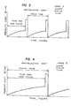
- a simple predictive model can be used to estimate the incremental penalty cost cure and, thereby, infer model parameters P and K from on line measurements of the heat flux q as follows:
- Equation (17) Equation (17) can be solved for ⁇ opt by integrating the error from a null balance recursive solution technique.
- the model utilizes measurements of tube side fluid temperature (or enthalpy), which is readily available. No gas side furnace temperatures are necessary.
- the optimum cycle time ⁇ opt is determined instantaneously and adapts to varying operating and economic conditions.
- the optimum economic cycle time for each heat trap is determined independently of the other heat traps. However, interaction among the various heat traps is taken into account because each heat trap affects the overall efficiency and resultant incremental steam cost. Calculation of overall efficiency is based on the losses method and is not affected by the heat trap performance calculations.
- fluid flow as well as input and output temperatures are provided by transmitters 20, 22, and 24, respectively.
- the driving temperature is obtained in comparator 26 with its output multiplied by a flow rate in multiplication unit 28.
- the output is multiplied again by a constant which represents specific heat of the fluid (water) in multiplier 30.
- the output of multiplier 30 represents the heat flux in the tubes of the boiler at various times during boiler operation.
- ⁇ b the flux value for the end of the period is calculated and provided to a second com- parameter 32.
- a transfer terminal 34 holds the initial value for heat flux (right after a sootblowing operation) which is compared in comparator 32 to obtain a different value.
- the ratio of flow rate after the termination of the cycle to flow rate at the beginning of the cycle is supplied by element 36 which receives the ratio from a dividing element 38 and a terminal 40 for storing the initial value of flow rate.
- Transfer terminals 34 and 40 are operated by pulses from a gate 42 which is connected to a controller 44 that controls sootblowing initiation.
- Terminal 46 receives a value which corresponds to the scaling parameter K with that value and a value representing the incremental steam cost being provided to a multiplier 48.
- the incremental cost factor is calculated from a cost transmitter 50 and modified by a load transmitter 52 which process signals as shown in the logic circuitry 60 to generate incremental cost factor ⁇ .
- a dividing element 56 and a comparator 58 generate the scaling factor P.
- Terminals 62, 64, and 66 carry values P, the signal for the sootblower timer, and the value S, respectively.
- these terminals supply their respective signals to additional circuitry which is utilized to generate the optimum cycle time ⁇ opt which is supplied at terminal 70.
- the cycle time is manually set, for example, for maximum fuel efficiency and provided at terminal 72 which value is also used in the circuitry of Fig. 7 to generate the scaling parameter P.
- comparators 86 to 89 are utilized as well as lower limit detectors 90 to 97.
- AND gates98, 99, 100, and 101 compare Boolean logic signalsand only the AND gate with all positive inputs is activated to operate its respective sootblowing equipment which is connected to control elements 102, 103, 104, and 105, respectively.
Applications Claiming Priority (2)
| Application Number | Priority Date | Filing Date | Title |
|---|---|---|---|
| US40584082A | 1982-08-06 | 1982-08-06 | |
| US405840 | 1982-08-06 |
Publications (3)
| Publication Number | Publication Date |
|---|---|
| EP0101226A2 true EP0101226A2 (fr) | 1984-02-22 |
| EP0101226A3 EP0101226A3 (en) | 1985-05-15 |
| EP0101226B1 EP0101226B1 (fr) | 1989-12-06 |
Family
ID=23605468
Family Applications (1)
| Application Number | Title | Priority Date | Filing Date |
|---|---|---|---|
| EP83304383A Expired EP0101226B1 (fr) | 1982-08-06 | 1983-07-28 | Optimalisation de l'échappement de suie |
Country Status (15)
| Country | Link |
|---|---|
| EP (1) | EP0101226B1 (fr) |
| JP (1) | JPS5956609A (fr) |
| KR (1) | KR880001506B1 (fr) |
| AU (1) | AU556857B2 (fr) |
| BR (1) | BR8304232A (fr) |
| CA (1) | CA1203131A (fr) |
| DE (1) | DE3380941D1 (fr) |
| ES (1) | ES524531A0 (fr) |
| FI (1) | FI77122C (fr) |
| HK (1) | HK39190A (fr) |
| IN (1) | IN160086B (fr) |
| MX (1) | MX158789A (fr) |
| SE (1) | SE8304253L (fr) |
| SG (1) | SG14690G (fr) |
| ZA (1) | ZA835352B (fr) |
Cited By (3)
| Publication number | Priority date | Publication date | Assignee | Title |
|---|---|---|---|---|
| EP0132135A2 (fr) * | 1983-07-14 | 1985-01-23 | The Babcock & Wilcox Company | Optimalisation de l'échappement de suie d'une chaudière |
| GB2271440A (en) * | 1992-10-03 | 1994-04-13 | Boiler Management Systems Limi | Optimising boiler cleaning |
| US7891323B2 (en) | 2005-07-29 | 2011-02-22 | Clyde Bergemann Gmbh | Selective cleaning of heat exchanging devices in the boiler of a combustion plant |
Families Citing this family (1)
| Publication number | Priority date | Publication date | Assignee | Title |
|---|---|---|---|---|
| CN115510904B (zh) * | 2022-09-26 | 2023-08-01 | 天津大学 | 基于时序预测的锅炉受热面积灰监测方法 |
Citations (1)
| Publication number | Priority date | Publication date | Assignee | Title |
|---|---|---|---|---|
| FR1454034A (fr) * | 1965-08-19 | 1966-07-22 | Combustion Eng | Perfectionnements apportés aux foyers des générateurs de vapeur |
-
1983
- 1983-06-24 AU AU16245/83A patent/AU556857B2/en not_active Ceased
- 1983-06-29 FI FI832370A patent/FI77122C/fi not_active IP Right Cessation
- 1983-07-08 KR KR1019830003121A patent/KR880001506B1/ko not_active IP Right Cessation
- 1983-07-22 ZA ZA835352A patent/ZA835352B/xx unknown
- 1983-07-28 ES ES524531A patent/ES524531A0/es active Granted
- 1983-07-28 DE DE8383304383T patent/DE3380941D1/de not_active Expired - Fee Related
- 1983-07-28 EP EP83304383A patent/EP0101226B1/fr not_active Expired
- 1983-08-03 IN IN966/CAL/83A patent/IN160086B/en unknown
- 1983-08-03 BR BR8304232A patent/BR8304232A/pt not_active IP Right Cessation
- 1983-08-03 SE SE8304253A patent/SE8304253L/ unknown
- 1983-08-05 CA CA000433965A patent/CA1203131A/fr not_active Expired
- 1983-08-05 JP JP58142611A patent/JPS5956609A/ja active Granted
- 1983-08-05 MX MX198294A patent/MX158789A/es unknown
-
1990
- 1990-03-02 SG SG146/90A patent/SG14690G/en unknown
- 1990-05-24 HK HK391/90A patent/HK39190A/xx unknown
Patent Citations (1)
| Publication number | Priority date | Publication date | Assignee | Title |
|---|---|---|---|---|
| FR1454034A (fr) * | 1965-08-19 | 1966-07-22 | Combustion Eng | Perfectionnements apportés aux foyers des générateurs de vapeur |
Non-Patent Citations (1)
| Title |
|---|
| Advances in Instrumentation, Vol. 2, No. 2, October 1973, pages 660.1 - 660.7. A. WAXMAN P.E.: "optimizing and adaptive control systems for fossil fuel steam generators". *whole document* * |
Cited By (6)
| Publication number | Priority date | Publication date | Assignee | Title |
|---|---|---|---|---|
| EP0132135A2 (fr) * | 1983-07-14 | 1985-01-23 | The Babcock & Wilcox Company | Optimalisation de l'échappement de suie d'une chaudière |
| EP0132135A3 (en) * | 1983-07-14 | 1985-05-15 | The Babcock & Wilcox Company | Boiler sootblowing optimization |
| AU578618B2 (en) * | 1983-07-14 | 1988-11-03 | International Control Automation Finance Sa | Enhanced sootblowing system |
| EP0313687A2 (fr) | 1983-07-14 | 1989-05-03 | International Control Automation Finance S.A. | Modeler la perte d'efficacité d'une chaudière causée par le nettoyage de suie |
| GB2271440A (en) * | 1992-10-03 | 1994-04-13 | Boiler Management Systems Limi | Optimising boiler cleaning |
| US7891323B2 (en) | 2005-07-29 | 2011-02-22 | Clyde Bergemann Gmbh | Selective cleaning of heat exchanging devices in the boiler of a combustion plant |
Also Published As
| Publication number | Publication date |
|---|---|
| JPH059689B2 (fr) | 1993-02-05 |
| ES8406695A1 (es) | 1984-08-01 |
| SE8304253D0 (sv) | 1983-08-03 |
| AU556857B2 (en) | 1986-11-20 |
| FI77122C (fi) | 1989-01-10 |
| KR880001506B1 (ko) | 1988-08-16 |
| SG14690G (en) | 1990-07-06 |
| SE8304253L (sv) | 1984-02-07 |
| ZA835352B (en) | 1984-03-28 |
| MX158789A (es) | 1989-03-13 |
| FI77122B (fi) | 1988-09-30 |
| AU1624583A (en) | 1984-02-09 |
| FI832370A0 (fi) | 1983-06-29 |
| ES524531A0 (es) | 1984-08-01 |
| HK39190A (en) | 1990-06-01 |
| KR840006068A (ko) | 1984-11-21 |
| FI832370L (fi) | 1984-02-07 |
| EP0101226B1 (fr) | 1989-12-06 |
| CA1203131A (fr) | 1986-04-15 |
| DE3380941D1 (de) | 1990-01-11 |
| BR8304232A (pt) | 1984-03-13 |
| JPS5956609A (ja) | 1984-04-02 |
| EP0101226A3 (en) | 1985-05-15 |
| IN160086B (fr) | 1987-06-27 |
Similar Documents
| Publication | Publication Date | Title |
|---|---|---|
| US4454840A (en) | Enhanced sootblowing system | |
| US4475482A (en) | Sootblowing optimization | |
| EP0137709B1 (fr) | Optimalisation du nettoyage des chaudières | |
| US4539840A (en) | Sootblowing system with identification of model parameters | |
| US7890214B2 (en) | Method and apparatus for controlling soot blowing using statistical process control | |
| US4996951A (en) | Method for soot blowing automation/optimization in boiler operation | |
| EP2444869B1 (fr) | Procédé et appareil pour l'évaluation de la performance généralisée d'un équipement au moyen de la performance réalisable dérivée de statistiques et de données en temps réel | |
| US5181482A (en) | Sootblowing advisor and automation system | |
| EP3521748B1 (fr) | Approche de modèle double pour le calcul de la propreté d'une section de chaudière | |
| US3412786A (en) | Fouling degree computer for heat exchanger cleaner | |
| EP0101226A2 (fr) | Optimalisation de l'échappement de suie | |
| DK2737273T3 (en) | METHOD FOR INCREASING THE IMPACT DEGREE IN INCINERATION PLANTS IN PARTICULAR a waste OR BIOMASS POWER PLANT | |
| Bujalski et al. | The algorithm of steam soot blowers operation based on the monitoring of fouling factors of heating surfaces of a coal-fired boiler under operating conditions | |
| SU1765614A1 (ru) | Способ управлени средствами очистки экранов топки паровых котлов | |
| JPS63286609A (ja) | スートブロワ制御装置 | |
| JPS588911A (ja) | ス−トブロワ制御方法 | |
| JP2001065856A (ja) | リジェネレーティブ燃焼方法 | |
| JPS5787528A (en) | Soot blower controller | |
| JPS6026213A (ja) | ス−ツブロアの最適制御システム | |
| JPH01266416A (ja) | ボイラに於けるスートブロワ運転制御方法 |
Legal Events
| Date | Code | Title | Description |
|---|---|---|---|
| PUAI | Public reference made under article 153(3) epc to a published international application that has entered the european phase |
Free format text: ORIGINAL CODE: 0009012 |
|
| AK | Designated contracting states |
Designated state(s): DE FR GB IT |
|
| PUAL | Search report despatched |
Free format text: ORIGINAL CODE: 0009013 |
|
| AK | Designated contracting states |
Designated state(s): DE FR GB IT |
|
| 17P | Request for examination filed |
Effective date: 19851102 |
|
| 17Q | First examination report despatched |
Effective date: 19870305 |
|
| ITF | It: translation for a ep patent filed |
Owner name: ST. ASSOC. MARIETTI & PIPPARELLI |
|
| GRAA | (expected) grant |
Free format text: ORIGINAL CODE: 0009210 |
|
| AK | Designated contracting states |
Kind code of ref document: B1 Designated state(s): DE FR GB IT |
|
| REF | Corresponds to: |
Ref document number: 3380941 Country of ref document: DE Date of ref document: 19900111 |
|
| ET | Fr: translation filed | ||
| PGFP | Annual fee paid to national office [announced via postgrant information from national office to epo] |
Ref country code: GB Payment date: 19900625 Year of fee payment: 8 |
|
| PGFP | Annual fee paid to national office [announced via postgrant information from national office to epo] |
Ref country code: FR Payment date: 19900718 Year of fee payment: 8 |
|
| PGFP | Annual fee paid to national office [announced via postgrant information from national office to epo] |
Ref country code: DE Payment date: 19900726 Year of fee payment: 8 |
|
| ITTA | It: last paid annual fee | ||
| PLBE | No opposition filed within time limit |
Free format text: ORIGINAL CODE: 0009261 |
|
| STAA | Information on the status of an ep patent application or granted ep patent |
Free format text: STATUS: NO OPPOSITION FILED WITHIN TIME LIMIT |
|
| 26N | No opposition filed | ||
| PG25 | Lapsed in a contracting state [announced via postgrant information from national office to epo] |
Ref country code: GB Effective date: 19910728 |
|
| GBPC | Gb: european patent ceased through non-payment of renewal fee | ||
| PG25 | Lapsed in a contracting state [announced via postgrant information from national office to epo] |
Ref country code: FR Effective date: 19920331 |
|
| PG25 | Lapsed in a contracting state [announced via postgrant information from national office to epo] |
Ref country code: DE Effective date: 19920401 |
|
| REG | Reference to a national code |
Ref country code: FR Ref legal event code: ST |