EP0101014B1 - Elektronisches Blitzgerät - Google Patents
Elektronisches Blitzgerät Download PDFInfo
- Publication number
- EP0101014B1 EP0101014B1 EP83107652A EP83107652A EP0101014B1 EP 0101014 B1 EP0101014 B1 EP 0101014B1 EP 83107652 A EP83107652 A EP 83107652A EP 83107652 A EP83107652 A EP 83107652A EP 0101014 B1 EP0101014 B1 EP 0101014B1
- Authority
- EP
- European Patent Office
- Prior art keywords
- reflector
- flashtube
- electronic flash
- flash apparatus
- equation
- Prior art date
- Legal status (The legal status is an assumption and is not a legal conclusion. Google has not performed a legal analysis and makes no representation as to the accuracy of the status listed.)
- Expired
Links
Images

Classifications
-
- G—PHYSICS
- G03—PHOTOGRAPHY; CINEMATOGRAPHY; ANALOGOUS TECHNIQUES USING WAVES OTHER THAN OPTICAL WAVES; ELECTROGRAPHY; HOLOGRAPHY
- G03B—APPARATUS OR ARRANGEMENTS FOR TAKING PHOTOGRAPHS OR FOR PROJECTING OR VIEWING THEM; APPARATUS OR ARRANGEMENTS EMPLOYING ANALOGOUS TECHNIQUES USING WAVES OTHER THAN OPTICAL WAVES; ACCESSORIES THEREFOR
- G03B15/00—Special procedures for taking photographs; Apparatus therefor
- G03B15/02—Illuminating scene
- G03B15/03—Combinations of cameras with lighting apparatus; Flash units
- G03B15/05—Combinations of cameras with electronic flash apparatus; Electronic flash units
-
- G—PHYSICS
- G03—PHOTOGRAPHY; CINEMATOGRAPHY; ANALOGOUS TECHNIQUES USING WAVES OTHER THAN OPTICAL WAVES; ELECTROGRAPHY; HOLOGRAPHY
- G03B—APPARATUS OR ARRANGEMENTS FOR TAKING PHOTOGRAPHS OR FOR PROJECTING OR VIEWING THEM; APPARATUS OR ARRANGEMENTS EMPLOYING ANALOGOUS TECHNIQUES USING WAVES OTHER THAN OPTICAL WAVES; ACCESSORIES THEREFOR
- G03B2215/00—Special procedures for taking photographs; Apparatus therefor
- G03B2215/05—Combinations of cameras with electronic flash units
- G03B2215/0514—Separate unit
- G03B2215/0517—Housing
- G03B2215/0525—Reflector
- G03B2215/0528—Reflector movable reflector, e.g. change of illumination angle or illumination direction
Definitions
- the present invention relates to an electronic flash device with a flash tube lying horizontally in the normal position of use in an elongated, substantially uniform, trough-shaped reflector and with a device for the adjustable deflection of the emitted light beams for partially indirect lighting.
- the reflector is successively divided in sections into at least three partial reflectors, of which at least one partial reflector radiates directly onto the object and at least two partial reflectors can be pivoted upward around the flash tube from the direct emission direction for indirect illumination.
- "normal position of use” is meant using the device for shots in landscape format.
- Such a flash unit is described, for example, in DE-B-2 740 487.
- GB-A-2 026 720 also discloses the use of a reflector whose curvature is a modified parabola of the shape follows.
- the desired change in the radiation angle of the reflector is only slight, it is sufficient to provide only the possibility of changing the position assignment of the lamp and reflector. Larger changes in the beam angle must also be taken into account by redesigning the curvature of the reflection surface of the reflector, because otherwise the necessary uniform illumination of the usable surface cannot be maintained.
- the object of the present invention is to further develop the electronic flash device described in the introduction in such a way that it can be used to produce tufts of light adapted to objectives with focal lengths from 24 mm to 100 mm.
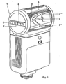
- a flash tube 2 lies in a cylindrical housing section 1 in a reflector 3, which is made up of partial reflectors 3 ', 3 ", 3"' 'which are successively assigned in sections (FIG. 1).
- the partial reflectors can be pivoted about the flash tube 2.
- a corresponding pivot mechanism and a handle 6 for pivoting the two partial reflectors 3 ', 3 "' or all three partial reflectors 3 ', 3", 3 "' is provided.
- direct, indirect or at the same time direct and indirect lighting can be generated.
- the flash tube 2 can be moved parallel to the optical axis of the reflector 3.
- a slide 7 is provided for moving the flash tube 2 into the desired position relative to the reflector 3. Tufts of light, adapted to lenses with focal lengths from 24 mm to 100 mm, can be produced.
- the flash tube can be moved by a maximum of 1.5 mm.
- the course of curvature of the reflection surface of the partial reflectors 3 ', 3 ", 3"' is preferably composed of two successive curve sections I, 11 lying in this region R (solid curve), wherein
- Section I with 0 ⁇ y ⁇ 12 of the equation and Section II with 12 ⁇ y ⁇ 15.9 of the equation obey.
Landscapes
- Physics & Mathematics (AREA)
- General Physics & Mathematics (AREA)
- Securing Globes, Refractors, Reflectors Or The Like (AREA)
- Stroboscope Apparatuses (AREA)
- Optical Elements Other Than Lenses (AREA)
Description
- Die vorliegende Erfindung betrifft ein elektronisches Blitzgerät mit einer in normaler Gebrauchslage horizontal liegenden Blitzröhre in einem langgestreckten, im wesentlichen gleichförmigen, wannenförmigen Reflektor sowie mit einer Einrichtung zum einstellbaren Umlenken der abgegebenen Lichtstrahlen für eine teilweise indirekte Beleuchtung. Der Reflektor ist abschnittsweise aufeinanderfolgend in zumindest drei Teilreflektoren unterteilt, von denen zumindest ein Teilreflektor direkt auf das Objekt abstrahlt und zumindest zwei Teilreflektoren um die Blitzröhre aus der direkten Ausstrahlrichtung nach oben wegschwenkbar sind für die indirekte Beleuchtung. Mit »normaler Gebrauchslage« ist eine Gerätbenutzung für Aufnahmen im Querformat gemeint. Ein derartiges Blitzgerät beschreibt beispielsweise die DE-B-2 740 487.
- Es ist bspw. aus der DE-A-2 347 287 bekannt, durch Veränderung der Lagezuordnung von Lampe und Reflektor den Abstrahlwinkel eines Reflektors zur Anpassung an Objektive zu verändern. Aus der GB-A-2 026 720 ist außerdem die Verwendung eines Reflektors bekannt, dessen Krümmung einer modifizierten Parabel der Form

- Ist die angestrebte Änderung des Abstrahlwinkels des Reflektors nur geringfügig, ist es hinreichend, lediglich die Möglichkeit der Veränderung der Lagezuordnung von Lampe und Reflektor vorzusehen. Größeren Änderungen des Abstrahlwinkels ist zusätzlich durch Neugestalten der Krümmung der Reflexionsfläche des Reflektors Rechnung zu tragen, weil sonst die notwendige gleichmäßige Ausleuchtung der Nutzfläche nicht beibehalten werden kann.
- Aufgabe der vorliegenden Erfindung ist es, das einleitend beschriebene elektronische Blitzgerät derart weiterzubilden, daß mit ihm Lichtbüschel, angepaßt an Objektive mit Brennweiten von 24 mm bis 100 mm erzeugt werden können.
- Erfindungsgemäß besteht die Lösung dieser Aufgabe darin, daß die Krümmung der Reflexionsfläche der Teilreflektoren in einem von den Kurven
- A: y2 = 19,4x-0,3593x2 und
- B: y2 = 16x-0,2666x2
- Weitere Einzelheiten ergeben sich aus der folgenden Beschreibung mit Zeichnungen. Von den Figuren zeigt
- Fig. 1 eine schematische perspektivische Darstellung des elektronischen Blitzgerätes
- Fig. 2 den Bereich in kartesischer Koordinierung, in dem die Krümmung der Reflexionsfläche der Teilreflektoren zu verlaufen hat sowie den bevorzugten Krümmungsverlauf.
- In einem zylinderförmigen Gehäuseabschnitt 1 liegt eine Blitzröhre 2 in einem Reflektor 3, der aus abschnittsweise aufeinanderfolgend zugeordneten Teilreflektoren 3', 3", 3''' aufgebaut ist (Fig. 1). Die Teilreflektoren sind um die Blitzröhre 2 schwenkbar. Ein entsprechender Schwenkmechanismus und eine Handhabe 6 zum Verschwenken der beiden Teilreflektoren 3', 3"' bzw. aller drei Teilreflektoren 3', 3", 3"' ist vorgesehen. Es kann je nach Stellung der Teilreflektoren allein direkte, indirekte oder gleichzeitig direkte und indirekte Beleuchtung erzeugt werden.
- Die Blitzröhre 2 ist parallel zur optischen Achse des Reflektors 3 verschiebbar. In einer Nut 5 der Handhabe 6 zum Schwenken der Teilreflektoren ist ein Schieber 7 zum Verschieben der Blitzröhre 2 in die gewünschte Stellung gegenüber dem Reflektor 3 vorgesehen. Es lassen sich Lichtbüschel, angepaßt an Objektive mit Brennweiten von 24 mm bis 100 mm erzeugen. Die Blitzröhre kann um maximal 1,5 mm bewegt werden.
- Um die gewünschte Lichtverteilung zu erhalten, ist die Krümmung der Reflexionsfläche derart gewählt, daß sie in einem Bereich R kartesischer Koordinierung verläuft, den die Kurven
- A: y2 = 19,4x-0,3593x2 und
- B: y2 = 16x-0,2666x2
- Bevorzugt setzt sich der Krümmungsverlauf der Reflexionsfläche der Teilreflektoren 3', 3", 3"' aus zwei in diesem Bereich R liegenden aufeinanderfolgenden Kurvenabschnitten I, 11 zusammen (ausgezogene Kurve), wobei
- Abschnitt I mit 0 < y < 12 der Gleichung


begrenzten Bereich verläuft und die Blitzröhre um maximal 1,5 mm parallel zur optischen Achse des Reflektors verschiebbar ist.
begrenzen (Fig. 2).
Claims (2)
begrenzten Bereich (R) verläuft und die Blitzröhre (2) um maximal 1,5 mm parallel zur optischen Achse des Reflektors (3) verschiebbar ist.


Applications Claiming Priority (2)
| Application Number | Priority Date | Filing Date | Title |
|---|---|---|---|
| DE19823229272 DE3229272A1 (de) | 1982-08-05 | 1982-08-05 | Elektronisches blitzgeraet |
| DE3229272 | 1982-08-05 |
Publications (3)
| Publication Number | Publication Date |
|---|---|
| EP0101014A2 EP0101014A2 (de) | 1984-02-22 |
| EP0101014A3 EP0101014A3 (en) | 1984-05-30 |
| EP0101014B1 true EP0101014B1 (de) | 1985-11-13 |
Family
ID=6170217
Family Applications (1)
| Application Number | Title | Priority Date | Filing Date |
|---|---|---|---|
| EP83107652A Expired EP0101014B1 (de) | 1982-08-05 | 1983-08-03 | Elektronisches Blitzgerät |
Country Status (3)
| Country | Link |
|---|---|
| EP (1) | EP0101014B1 (de) |
| JP (1) | JPS5933435A (de) |
| DE (2) | DE3229272A1 (de) |
Cited By (1)
| Publication number | Priority date | Publication date | Assignee | Title |
|---|---|---|---|---|
| DE4130992A1 (de) * | 1991-09-18 | 1993-03-25 | Kodak Ag | Blitzvorrichtung zum uebertragen einer farbstoffmatrix |
Family Cites Families (4)
| Publication number | Priority date | Publication date | Assignee | Title |
|---|---|---|---|---|
| DE2347287A1 (de) * | 1973-09-20 | 1975-04-03 | Thum Karl Heinrich | Leuchtwinkelregulierung fuer elektronenblitzgeraete und filmleuchten |
| DE2740487C3 (de) | 1977-09-08 | 1981-06-19 | Patent-Treuhand-Gesellschaft für elektrische Glühlampen mbH, 8000 München | Elektronisches Blitzgerät |
| FR2431090A1 (fr) * | 1978-07-10 | 1980-02-08 | Patent Treuhand Ges Fuer Elektrische Gluehlampen Mbh | Appareil electronique a eclats comportant un reflecteur a elements orientables |
| US4356538A (en) * | 1980-08-04 | 1982-10-26 | Polaroid Corporation | Photographic lighting apparatus |
-
1982
- 1982-08-05 DE DE19823229272 patent/DE3229272A1/de not_active Withdrawn
-
1983
- 1983-07-14 JP JP58127023A patent/JPS5933435A/ja active Pending
- 1983-08-03 DE DE8383107652T patent/DE3361229D1/de not_active Expired
- 1983-08-03 EP EP83107652A patent/EP0101014B1/de not_active Expired
Cited By (1)
| Publication number | Priority date | Publication date | Assignee | Title |
|---|---|---|---|---|
| DE4130992A1 (de) * | 1991-09-18 | 1993-03-25 | Kodak Ag | Blitzvorrichtung zum uebertragen einer farbstoffmatrix |
Also Published As
| Publication number | Publication date |
|---|---|
| DE3229272A1 (de) | 1984-02-09 |
| EP0101014A3 (en) | 1984-05-30 |
| DE3361229D1 (en) | 1985-12-19 |
| JPS5933435A (ja) | 1984-02-23 |
| EP0101014A2 (de) | 1984-02-22 |
Similar Documents
| Publication | Publication Date | Title |
|---|---|---|
| DE2144300C3 (de) | Beleuchtungsanordnung | |
| DE2740487C3 (de) | Elektronisches Blitzgerät | |
| DE2925456A1 (de) | Beleuchtungskoerper fuer strassenbeleuchtung | |
| DE4341555A1 (de) | Vorrichtung zum Bündeln und Übertragen von Licht | |
| DE1472179C2 (de) | Diaskop-Projektionsgerät | |
| DE19519264A1 (de) | Projektionsscheinwerfer | |
| DE4241719A1 (de) | ||
| EP0735311A1 (de) | Beleuchtungssystem für einen Innenraum | |
| DE3826988A1 (de) | Fahrzeugscheinwerfer | |
| DE1907939C3 (de) | Schlitz- oder Spalt-Belichtungsvorrichtung mit einer Einrichtung zum Ausgleichen der ungleichmäßigen Verteilung der Beleuchtungsintensität | |
| DE2830321C3 (de) | Elektronisches Blitzgerät | |
| EP0101014A2 (de) | Elektronisches Blitzgerät | |
| DE2936054A1 (de) | Arbeitsplatzleuchte | |
| EP1275898A2 (de) | Innenraumleuchte mit variablem, indirektem Lichtanteil | |
| DE3711366C2 (de) | ||
| DE2511030A1 (de) | Beleuchtungskoerper insbesondere fuer refraktierende flaechenbeleuchtung | |
| DE3633440C2 (de) | Reflektor und Abschirmungssystem für eine Leuchte mit linear ausgedehnter Lichtquelle | |
| DE69535403T2 (de) | Elektronische weitwinkel-beleuchtungsvorrichtung | |
| DE826469C (de) | Tischleuchte fuer Leuchtstofflampen | |
| EP0508163A2 (de) | Leuchte mit Spiegeloptik | |
| DE10231531B4 (de) | Schutzrohrleuchte | |
| DE102022115250B4 (de) | Linsenoptik zur flexiblen positionierung von lichtquellen | |
| DE9113944U1 (de) | Hinweisleuchte | |
| DE846139C (de) | Beleuchtungsvorrichtung fuer Flugplaetze, Leuchttuerme u. dgl. | |
| DE10020348B4 (de) | Reflektor für elektromagnetische Strahlen |
Legal Events
| Date | Code | Title | Description |
|---|---|---|---|
| PUAI | Public reference made under article 153(3) epc to a published international application that has entered the european phase |
Free format text: ORIGINAL CODE: 0009012 |
|
| AK | Designated contracting states |
Designated state(s): DE FR GB IT |
|
| PUAL | Search report despatched |
Free format text: ORIGINAL CODE: 0009013 |
|
| AK | Designated contracting states |
Designated state(s): DE FR GB IT |
|
| 17P | Request for examination filed |
Effective date: 19840629 |
|
| ITF | It: translation for a ep patent filed | ||
| GRAA | (expected) grant |
Free format text: ORIGINAL CODE: 0009210 |
|
| AK | Designated contracting states |
Designated state(s): DE FR GB IT |
|
| REF | Corresponds to: |
Ref document number: 3361229 Country of ref document: DE Date of ref document: 19851219 |
|
| ET | Fr: translation filed | ||
| PLBE | No opposition filed within time limit |
Free format text: ORIGINAL CODE: 0009261 |
|
| STAA | Information on the status of an ep patent application or granted ep patent |
Free format text: STATUS: NO OPPOSITION FILED WITHIN TIME LIMIT |
|
| 26N | No opposition filed | ||
| ITPR | It: changes in ownership of a european patent |
Owner name: CESSIONE;CULLMANN GMBH |
|
| PGFP | Annual fee paid to national office [announced via postgrant information from national office to epo] |
Ref country code: FR Payment date: 19910807 Year of fee payment: 9 |
|
| ITTA | It: last paid annual fee | ||
| REG | Reference to a national code |
Ref country code: FR Ref legal event code: TP |
|
| REG | Reference to a national code |
Ref country code: GB Ref legal event code: 732 |
|
| PGFP | Annual fee paid to national office [announced via postgrant information from national office to epo] |
Ref country code: GB Payment date: 19920724 Year of fee payment: 10 |
|
| PGFP | Annual fee paid to national office [announced via postgrant information from national office to epo] |
Ref country code: DE Payment date: 19920807 Year of fee payment: 10 |
|
| PG25 | Lapsed in a contracting state [announced via postgrant information from national office to epo] |
Ref country code: FR Effective date: 19930430 |
|
| REG | Reference to a national code |
Ref country code: FR Ref legal event code: ST |
|
| PG25 | Lapsed in a contracting state [announced via postgrant information from national office to epo] |
Ref country code: GB Effective date: 19930803 |
|
| GBPC | Gb: european patent ceased through non-payment of renewal fee |
Effective date: 19930803 |
|
| PG25 | Lapsed in a contracting state [announced via postgrant information from national office to epo] |
Ref country code: DE Effective date: 19940503 |