EP0100668B1 - Système de transmission de données au moyen du réseau - Google Patents
Système de transmission de données au moyen du réseau Download PDFInfo
- Publication number
- EP0100668B1 EP0100668B1 EP83304412A EP83304412A EP0100668B1 EP 0100668 B1 EP0100668 B1 EP 0100668B1 EP 83304412 A EP83304412 A EP 83304412A EP 83304412 A EP83304412 A EP 83304412A EP 0100668 B1 EP0100668 B1 EP 0100668B1
- Authority
- EP
- European Patent Office
- Prior art keywords
- terminal
- main unit
- signal
- terminals
- data signal
- Prior art date
- Legal status (The legal status is an assumption and is not a legal conclusion. Google has not performed a legal analysis and makes no representation as to the accuracy of the status listed.)
- Expired
Links
- 230000005540 biological transmission Effects 0.000 title claims description 12
- 238000005070 sampling Methods 0.000 description 15
- 230000000694 effects Effects 0.000 description 4
- 238000000034 method Methods 0.000 description 4
- 238000010586 diagram Methods 0.000 description 3
- 230000008054 signal transmission Effects 0.000 description 3
- 230000002159 abnormal effect Effects 0.000 description 2
- 238000005286 illumination Methods 0.000 description 2
- 238000011084 recovery Methods 0.000 description 2
- 230000002411 adverse Effects 0.000 description 1
- 230000001419 dependent effect Effects 0.000 description 1
- 230000007257 malfunction Effects 0.000 description 1
- 230000011664 signaling Effects 0.000 description 1
- 230000002269 spontaneous effect Effects 0.000 description 1
- 230000001360 synchronised effect Effects 0.000 description 1
- 239000002699 waste material Substances 0.000 description 1
Images



Classifications
-
- H—ELECTRICITY
- H04—ELECTRIC COMMUNICATION TECHNIQUE
- H04B—TRANSMISSION
- H04B3/00—Line transmission systems
- H04B3/54—Systems for transmission via power distribution lines
- H04B3/546—Combination of signalling, telemetering, protection
-
- H—ELECTRICITY
- H04—ELECTRIC COMMUNICATION TECHNIQUE
- H04L—TRANSMISSION OF DIGITAL INFORMATION, e.g. TELEGRAPHIC COMMUNICATION
- H04L12/00—Data switching networks
- H04L12/28—Data switching networks characterised by path configuration, e.g. LAN [Local Area Networks] or WAN [Wide Area Networks]
- H04L12/40—Bus networks
- H04L12/403—Bus networks with centralised control, e.g. polling
-
- H—ELECTRICITY
- H04—ELECTRIC COMMUNICATION TECHNIQUE
- H04B—TRANSMISSION
- H04B2203/00—Indexing scheme relating to line transmission systems
- H04B2203/54—Aspects of powerline communications not already covered by H04B3/54 and its subgroups
- H04B2203/5404—Methods of transmitting or receiving signals via power distribution lines
- H04B2203/5408—Methods of transmitting or receiving signals via power distribution lines using protocols
-
- H—ELECTRICITY
- H04—ELECTRIC COMMUNICATION TECHNIQUE
- H04B—TRANSMISSION
- H04B2203/00—Indexing scheme relating to line transmission systems
- H04B2203/54—Aspects of powerline communications not already covered by H04B3/54 and its subgroups
- H04B2203/5429—Applications for powerline communications
- H04B2203/5458—Monitor sensor; Alarm systems
Definitions
- the present invention relates to a system for transmitting data via a power supply line, using a high frequency AC signal synchronously mixed with the AC commercial frequency cycle, the system comprising a main unit and a plurality of terminals, and being operable to survey the conditions of the terminals.
- FIG. 1 shows a simplified diagram of a conventional data transmission system using an AC power supply line.
- Central processing unit (CPU) 1 transmits the control command to the terminal units 2 via the power supply line 3 by turning switches on and off to execute the designated operation, for example, On/Off operations for power and illumination, while it usually surveys and displays the operative conditions of respective terminal units 2, for example, current conditions of the power source, illumination, or sensors, or alternatively, it causes an alarm to be generated in case of an emergency.
- These terminal units 2 incorporate a self-selective function so that each can enter operation only when a respective specific signal is detected.
- the first is a method of contention, by which signal transmission can be started upon contesting available channel lines as soon as such a need for signal transmission arises.
- the second is the time division stationary slot allocation system, which, as shown in Figure 2, activates the CPU 1 to output a specific code H in order to establish a system synchronization before either transmitting or receiving data 21 through 25 to and from respective terminal units 2 via the preliminarly allocated slots.
- the third is the polling system, which, as shown in Figure 3, activates the CPU 1 to output signals P1, P2, and P3, each containing an address signal, while any of the terminal units 2 selected by these signals can feed back any data such as D1, D2, and D3.
- the second one which is the time division stationary slot allocation system, also requires a long time to collect sampling data in each cycle if a large number of terminal units 2 are employed, since the CPU 1 will also be obliged to stop sending the control command until the next data are completely collected.
- the third one which is the polling system can collect the sampling data within a very short while in each cycle without causing the CPU 1 to stop sending the control command without any waste of time.
- GB-2039402 discloses a data transmission system conforming with the third type discussed above. It comprises a central processing unit, a plurality of terminal units connected to the central processing unit over a power line through which high frequency AC signals are synchronously mixed with the AC supply frequency cycle so that such terminals are controlled and interrogated using a polling method.
- This known system suffers the disadvantage mentioned above, namely that it cannot respond quickly to a change in status occurring at a terminal unit immediately after it has been polled.
- DE-2844453 discloses a data transmission system which uses a polling technique, and in which there is provided means to permit spontaneously arising data to be transmitted with contention to the central unit after each terminal unit is polled; this is achieved by causing a call to go out to all of the terminal units after each unit polling. A unit at which such spontaneous data is present is deliberately interrogated. In this system, however, the central unit has to generate and transmit call signals to all of the terminal units.
- a system for transmitting data via an AC power supply line using a high frequency AC signal synchronously mixed with the AC commercial frequency cycle comprising a main unit and a plurality of terminals interconnected by the supply line, the main unit being operable to poll the terminals for transmission of information between the main unit and the terminals, characterised in that after each terminal is polled by a polling signal from the main unit, the terminals are capable of responding to emergency conditions at the respective terminal by transmitting spontaneously and without being interrogated by special interrogation signals from the main unit, an emergency data signal in synchronism with a specific cycle period of the AC power supply via said supply line, and in that means is provided to resolve contention for access to the supply line for transmission of a said emergency data signal by different said terminals.
- terminal wishes to transmit emergency data it does not have to wait until it is polled, neither does it have to rely upon receipt of a specially generated call signal, before signalling its condition to the central unit. It merely awaits the said specific cycle, which it can itself determine, and then transmits said emergency data signal.
- all other terminals are capable of transmitting a said emergency data signal (37).
- Central processing unit 1 comprises a microprocessor 4, a transmitter 5, a receiver 6, a switching unit 7, a display unit 8, and an alarm unit 9.
- Switching unit 7 has switches instructing every terminal unit to perform ON/OFF operations.
- Display unit 8 displays the actual status of the connected terminal units 2 by means of LED, CRT, and lamps.
- Alarm unit 9 generates alarm sound, for example, by buzzer, if any abnormal condition arises at any of the connected terminal units 2.
- Each of the terminal units 2 is also provided with a microprocessor 10, transmitter 11, and receiver 12.
- Addressing switch unit 13 provides each terminal unit 2 with a respective address.
- Sensor unit 14 confirms the operation of such a unit as a motor 15 being controlled by other units.
- Such a unit 15 as motor is being controlled, for example, by a load controller such as a relay 16 shown in Figure 4, which turns the unit 15 ON and OFF.
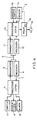
- Figure 5 is a flow-chart describing operations of the central processing unit 1, while Figure 6 is also a flowchart describing operations of the terminal units 2.
- the CPU 1 As soon as the CPU 1 receives an input from the switching unit 7, the CPU outputs the ON/OFF control command to the designated terminal unit 2, which then identifies whether the received ON/ OFF control command has been addressed to itself, and if so, it starts to control the ON/OFF operations of the related devices and simultaneously sends out an ACKNOWLEDGE signal to the CPU 1. On receipt of this signal, the CPU 1 decodes its contents and then displays the existing condition of the designated terminal unit 2 in the display unit 8.
- the period needed for the delivery of the control command for the ON/OFF operation of the terminal units is as described above, while the time actually needed for waiting until the command signal can be output corresponds to one round of the data sampling cycle, which in effect is a very short time.
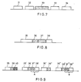
- FIG 8 shows a timing chart during the data sampling operation, which actually corresponds to one of the cases denoted by symbols 31 through 34 of Figure 7.
- the data sampling operation is described below with reference to the timing chart of Figure 8 and the flowcharts of Figure 5 and 6.
- symbol 35 indicates a polling signal delivered from the CPU 1 to a specific terminal unit 2 :
- the terminal unit 2 first identifies that the polling signal has been addressed to itself, and then samples the present status for encoding and delivering the answerback signal to the CPU 1 as ACKNOWLEDGE signal 36.
- Symbol 37 is an emergency signal fed from one of the terminal units 2 other than said specific one, where said emergency signal is output from one of the terminal units in a specific timing after the polling signal 35 has been detected, and using line contention, indicating that an abnormal condition exists in said terminal unit 2.
- Symbol 38 denotes the ACKNOWLEDGE signal output from the CPU 1 in response to said emergency signal.
- CPU 1 receives the ACKNOWLEDGE signal 36 from a designated terminal unit 2 for the polling, then displays the actual state of the terminal unit 2 and if appropriate generates an alarm.
- the CPU 1 however provides a period for permitting the sampled data to be received during a predetermined cycle. If a data received by the CPU 1 is identified as an emergency signal, the CPU 1 outputs the ACKNOWLEDGE signal 38 to the terminal unit 2 which sent such an emergency signal to the CPU 1.
- the CPU 1 then changes the display contents and simultaneously generates an alarm.
- the terminal unit 2 receives an instruction sent by the CPU to other units to deliver the sampled data, it first identifies whether an emergency signal should be output from itself, and if found necessary, it sets flag and outputs the emergency data to a specific cycle position corresponding to the data receiving period of the CPU 1. On receipt of the ACKNOWLEDGE signal 38 from the CPU 1, the terminal unit 2 resets and stops to output such an emergency signal.
- FIG. 9 shows a chart describing the recovery process from a collision which may have taken place between emergency signals from the two terminal units 2A and 2B.
- symbols 35, 35', 35", and 35'" denote the polling signals output from the CPU 1 for normal data sampling operations
- symbols 36, 36', 36", and 36'" are the ACKNOWLEDGE data output from the corresponding terminal units 2.
- All the emergency signals are preliminarily encoded so that they cannot be decoded when collided with each other. Actually, these signals can easily be encoded. For example, when emergency signals A and B collide with each other at the position 40 of Figure 9, since the CPU 1 cannot decode both signals, it executes the polling for sampling the next data by ignoring these emergency signals. As shown in the flow- chart of Figure 6, the terminal units 2A and 2B which respectively generated the emergency signals will continuously output emergency signals by any means such as a random delay, if no ACKNOWLEDGE signal is fed from the CPU 1, until they eventually receive the ACKNOWLEDGE signals 38 or until the units themselves are subjected to the polling.
- Random delay means enables the system to properly adjust the time needed for waiting to cause the intended operations to be repeatedly performed by using the random digit table.
- such a random delay operation corresponds to the act of repeating operations while determining whether such an emergency signal should be output during the ensuing polling operations.
- collided emergency signals A and B can eventually be separated to allow only the normal emergency signal to be transmitted.
- only the terminal unit A outputs an emergency signal at the position 37'
- the unit B outputs an emergency signal at the position 37"'
- these units A and B respectively receive the ACKNOWLEDGE signals 38' and 38'" so that the system can recover from the effect of the collision.
- the mean time can effectively be shortened unless there are many fractional numbers of the collision, although the mean time needed for recovering from the effect of the collision is dependent on the algorithm of the random number generation.
Landscapes
- Engineering & Computer Science (AREA)
- Computer Networks & Wireless Communication (AREA)
- Signal Processing (AREA)
- Power Engineering (AREA)
- Small-Scale Networks (AREA)
- Selective Calling Equipment (AREA)
- Remote Monitoring And Control Of Power-Distribution Networks (AREA)
- Cable Transmission Systems, Equalization Of Radio And Reduction Of Echo (AREA)
Claims (10)
Applications Claiming Priority (2)
| Application Number | Priority Date | Filing Date | Title |
|---|---|---|---|
| JP57133932A JPS5925536A (ja) | 1982-07-30 | 1982-07-30 | 電力線デ−タ伝送システム |
| JP133932/82 | 1982-07-30 |
Publications (3)
| Publication Number | Publication Date |
|---|---|
| EP0100668A2 EP0100668A2 (fr) | 1984-02-15 |
| EP0100668A3 EP0100668A3 (en) | 1985-08-07 |
| EP0100668B1 true EP0100668B1 (fr) | 1988-05-11 |
Family
ID=15116439
Family Applications (1)
| Application Number | Title | Priority Date | Filing Date |
|---|---|---|---|
| EP83304412A Expired EP0100668B1 (fr) | 1982-07-30 | 1983-07-29 | Système de transmission de données au moyen du réseau |
Country Status (5)
| Country | Link |
|---|---|
| US (1) | US4611274A (fr) |
| EP (1) | EP0100668B1 (fr) |
| JP (1) | JPS5925536A (fr) |
| CA (1) | CA1196977A (fr) |
| DE (1) | DE3376612D1 (fr) |
Families Citing this family (40)
| Publication number | Priority date | Publication date | Assignee | Title |
|---|---|---|---|---|
| US4866602A (en) * | 1983-11-02 | 1989-09-12 | Microsoft Corporation | Power supply for a computer peripheral device which positions a cursor on a computer display |
| DE3402076A1 (de) * | 1984-01-21 | 1985-08-01 | Philips Patentverwaltung Gmbh, 2000 Hamburg | Verfahren und anordnung zur datenuebertragung |
| JPS6194433A (ja) * | 1984-10-15 | 1986-05-13 | Mitsubishi Electric Corp | シリアルバスの制御方式 |
| US4910655A (en) * | 1985-08-14 | 1990-03-20 | Apple Computer, Inc. | Apparatus for transferring signals and data under the control of a host computer |
| US4918598A (en) * | 1985-08-14 | 1990-04-17 | Apple Computer, Inc. | Method for selectively activating and deactivating devices having same first address and different extended addresses |
| US4912627A (en) * | 1985-08-14 | 1990-03-27 | Apple Computer, Inc. | Method for storing a second number as a command address of a first peripheral device and a third number as a command address of a second peripheral device |
| US4875158A (en) * | 1985-08-14 | 1989-10-17 | Apple Computer, Inc. | Method for requesting service by a device which generates a service request signal successively until it is serviced |
| US4785396A (en) * | 1986-01-28 | 1988-11-15 | Intel Corporation | Push-pull serial bus coupled to a plurality of devices each having collision detection circuit and arbitration circuit |
| US4751495A (en) * | 1986-01-28 | 1988-06-14 | Raychem Corporation | Analog pulsed heat trace monitor or the like |
| US4716409A (en) * | 1986-07-16 | 1987-12-29 | Homestead Products, Inc. | Electrical appliance control system |
| US4806905A (en) * | 1986-10-01 | 1989-02-21 | Honeywell Inc. | Transmitter for transmitting on a two-wire transmitting line |
| JP2596569B2 (ja) * | 1987-12-22 | 1997-04-02 | 富士通株式会社 | ネットワーク通信方法 |
| CH677568A5 (fr) * | 1989-03-21 | 1991-05-31 | Datawatt Bv | |
| FR2656188B1 (fr) * | 1989-12-18 | 1996-10-18 | Telediffusion Fse | Installation a reseau filaire de distribution de programmes et de communication numerique et terminal pour une telle installation. |
| KR960009358B1 (ko) * | 1990-02-06 | 1996-07-18 | 배회환 | 조명기구 고장부위 집중 표시 장치 및 고장정보 수집방법 |
| US5241629A (en) * | 1990-10-05 | 1993-08-31 | Bull Hn Information Systems Inc. | Method and apparatus for a high performance round robin distributed bus priority network |
| EP0489944B1 (fr) * | 1990-12-08 | 1995-09-20 | Deutsche ITT Industries GmbH | Procédé de communication de données maître-esclave avec bus flexible à un câble |
| US5613065A (en) * | 1992-02-19 | 1997-03-18 | Fujitsu Limited | Information broadcasting system having reception error minimizing facility |
| CA2170380A1 (fr) * | 1993-02-11 | 1994-08-18 | O.S. Mogdil | Systeme de telemetrie et de commande |
| US5592621A (en) * | 1994-08-03 | 1997-01-07 | Emc Corporation | System for inserting first transmission token into data stream appended to second transmission token to facilitate full duplex communication between central controller and other controllers |
| US5818821A (en) * | 1994-12-30 | 1998-10-06 | Intelogis, Inc. | Universal lan power line carrier repeater system and method |
| US5553072A (en) * | 1995-01-30 | 1996-09-03 | Northrop Grumman Corporation | Communication apparatus and method |
| US5651114A (en) * | 1995-06-23 | 1997-07-22 | Lexmark International, Inc. | External network adapter for handling normal and alternate channel data over a single bi-directional channel connected to a printer |
| US5970127A (en) * | 1997-10-16 | 1999-10-19 | Phonex Corporation | Caller identification system for wireless phone jacks and wireless modem jacks |
| US6055435A (en) * | 1997-10-16 | 2000-04-25 | Phonex Corporation | Wireless telephone connection surge suppressor |
| US6107912A (en) * | 1997-12-08 | 2000-08-22 | Phonex Corporation | Wireless modem jack |
| KR100261512B1 (ko) | 1998-06-17 | 2000-07-15 | 김철 | 양 방향 전력선 통신을 이용한 원격제어장치 및 그 제어방법 |
| US6480510B1 (en) | 1998-07-28 | 2002-11-12 | Serconet Ltd. | Local area network of serial intelligent cells |
| US6246868B1 (en) | 1998-08-14 | 2001-06-12 | Phonex Corporation | Conversion and distribution of incoming wireless telephone signals using the power line |
| US6243571B1 (en) | 1998-09-21 | 2001-06-05 | Phonex Corporation | Method and system for distribution of wireless signals for increased wireless coverage using power lines |
| US6842459B1 (en) | 2000-04-19 | 2005-01-11 | Serconet Ltd. | Network combining wired and non-wired segments |
| US6373377B1 (en) | 2000-10-05 | 2002-04-16 | Conexant Systems, Inc. | Power supply with digital data coupling for power-line networking |
| US7151968B2 (en) | 2001-11-01 | 2006-12-19 | Salton, Inc. | Intelligent coffeemaker appliance |
| US7069091B2 (en) | 2001-11-01 | 2006-06-27 | Salton, Inc. | Intelligent microwave oven appliance |
| US20030189495A1 (en) * | 2002-04-03 | 2003-10-09 | Pettler Peter R. | Method and system for controlling a selected electrical load in a building |
| IL154921A (en) | 2003-03-13 | 2011-02-28 | Mosaid Technologies Inc | A telephone system that includes many separate sources and accessories for it |
| JP5114330B2 (ja) * | 2008-07-22 | 2013-01-09 | 京楽産業.株式会社 | Plc通信を用いた遊技ホール用ネットワークシステム |
| JP5114329B2 (ja) * | 2008-07-22 | 2013-01-09 | 京楽産業.株式会社 | Plc通信を用いた遊技ホール用ネットワークシステム |
| US9667318B2 (en) | 2010-05-11 | 2017-05-30 | Texas Instruments Corporation | Device and frame structure for powerline communications |
| US9112753B2 (en) * | 2010-05-11 | 2015-08-18 | Texas Instruments Incorporated | Interleaver design and header structure for ITU G.hnem |
Family Cites Families (11)
| Publication number | Priority date | Publication date | Assignee | Title |
|---|---|---|---|---|
| US4063220A (en) * | 1975-03-31 | 1977-12-13 | Xerox Corporation | Multipoint data communication system with collision detection |
| US4161786A (en) * | 1978-02-27 | 1979-07-17 | The Mitre Corporation | Digital bus communications system |
| DE2844453A1 (de) * | 1978-10-12 | 1980-04-24 | Bbc Brown Boveri & Cie | Verfahren zum uebertragen von fernwirktelegrammen im gemeinschaftsverkehr |
| CA1151261A (fr) * | 1979-01-05 | 1983-08-02 | Robertshaw Controls Company | Systeme de communication bidirectionnel par ligne de secteur a courant alternatif |
| US4429299A (en) * | 1979-01-05 | 1984-01-31 | Robertshaw Controls Company | Two-way AC power line communications system |
| GB2064923B (en) * | 1979-10-31 | 1984-02-08 | Matsushita Electric Works Ltd | Data transmission system utilising power line |
| US4283529A (en) * | 1980-03-03 | 1981-08-11 | Abbott Laboratories | 3-O-Demethyl derivatives of Sannamycin C and antibiotic AX-127B-1 |
| JPS5767355A (en) * | 1980-10-15 | 1982-04-23 | Nec Corp | Data transmission controlling system at loop transmission system |
| US4447872A (en) * | 1980-10-20 | 1984-05-08 | Minnesota Mining And Manufacturing Company | Alarm data concentration and gathering system |
| US4379294A (en) * | 1981-02-12 | 1983-04-05 | Electric Power Research Institute, Inc. | Data highway access control system |
| US4439856A (en) * | 1982-02-24 | 1984-03-27 | General Electric Company | Bimodal bus accessing system |
-
1982
- 1982-07-30 JP JP57133932A patent/JPS5925536A/ja active Pending
-
1983
- 1983-07-29 CA CA000433531A patent/CA1196977A/fr not_active Expired
- 1983-07-29 DE DE8383304412T patent/DE3376612D1/de not_active Expired
- 1983-07-29 US US06/518,450 patent/US4611274A/en not_active Expired - Fee Related
- 1983-07-29 EP EP83304412A patent/EP0100668B1/fr not_active Expired
Also Published As
| Publication number | Publication date |
|---|---|
| EP0100668A2 (fr) | 1984-02-15 |
| US4611274A (en) | 1986-09-09 |
| CA1196977A (fr) | 1985-11-19 |
| JPS5925536A (ja) | 1984-02-09 |
| EP0100668A3 (en) | 1985-08-07 |
| DE3376612D1 (en) | 1988-06-16 |
Similar Documents
| Publication | Publication Date | Title |
|---|---|---|
| US4611274A (en) | Data transmission system via power supply line | |
| US5230084A (en) | Selective call receiver having extended battery saving capability | |
| US3845472A (en) | Data communication system employing a series loop | |
| US5061922A (en) | Method of monitoring changes of state of a power transmission system by interruption signal transmission | |
| EP1731977B1 (fr) | Procédé de contrôle de la période de démarrage de la station maître de communication | |
| EP0140077B1 (fr) | Procédé pour contrôler l'accès à un moyen de communication dans un système CSMA avec évitement de collisions | |
| EP0125809A2 (fr) | Système de commande d'ordinateurs distribués | |
| US2501063A (en) | Station selector signaling system | |
| EP0143160B1 (fr) | Attribution d'adresses à des dispositifs d'entrée-sortie identiques éloignés | |
| US5107257A (en) | Bus relay apparatus for multi-data communication processing system | |
| US4646292A (en) | Link controller | |
| GB2178878A (en) | Alarm system with priority override | |
| JPH03121549A (ja) | チャネル装置の状態管理システム | |
| JPS57147353A (en) | Synchronization system | |
| JP3108478B2 (ja) | 多重伝送システムの割込処理方法 | |
| US2501592A (en) | Intercommunicating teletypewriter system | |
| JPS59168737A (ja) | マルチ・ドロツプ伝送方式 | |
| JPH0343657B2 (fr) | ||
| JPH0662023A (ja) | ポーリング方式 | |
| KR920005008B1 (ko) | 신호단말 제어장치의 송신중재회로 | |
| JPS63299597A (ja) | 監視情報伝送装置 | |
| JPS6471238A (en) | Fault processing system | |
| JPH02217039A (ja) | ポーリング/セレクティング制御手順方式 | |
| JPS6394733A (ja) | 信号伝送装置 | |
| JPS5620359A (en) | Telegram relay system |
Legal Events
| Date | Code | Title | Description |
|---|---|---|---|
| PUAI | Public reference made under article 153(3) epc to a published international application that has entered the european phase |
Free format text: ORIGINAL CODE: 0009012 |
|
| AK | Designated contracting states |
Designated state(s): DE FR GB IT |
|
| PUAL | Search report despatched |
Free format text: ORIGINAL CODE: 0009013 |
|
| AK | Designated contracting states |
Designated state(s): DE FR GB IT |
|
| 17P | Request for examination filed |
Effective date: 19860120 |
|
| 17Q | First examination report despatched |
Effective date: 19870112 |
|
| GRAA | (expected) grant |
Free format text: ORIGINAL CODE: 0009210 |
|
| ITF | It: translation for a ep patent filed | ||
| AK | Designated contracting states |
Kind code of ref document: B1 Designated state(s): DE FR GB IT |
|
| REF | Corresponds to: |
Ref document number: 3376612 Country of ref document: DE Date of ref document: 19880616 |
|
| ET | Fr: translation filed | ||
| PLBE | No opposition filed within time limit |
Free format text: ORIGINAL CODE: 0009261 |
|
| STAA | Information on the status of an ep patent application or granted ep patent |
Free format text: STATUS: NO OPPOSITION FILED WITHIN TIME LIMIT |
|
| 26N | No opposition filed | ||
| ITTA | It: last paid annual fee | ||
| PGFP | Annual fee paid to national office [announced via postgrant information from national office to epo] |
Ref country code: FR Payment date: 19960709 Year of fee payment: 14 |
|
| PGFP | Annual fee paid to national office [announced via postgrant information from national office to epo] |
Ref country code: GB Payment date: 19960722 Year of fee payment: 14 |
|
| PGFP | Annual fee paid to national office [announced via postgrant information from national office to epo] |
Ref country code: DE Payment date: 19960802 Year of fee payment: 14 |
|
| PG25 | Lapsed in a contracting state [announced via postgrant information from national office to epo] |
Ref country code: GB Free format text: LAPSE BECAUSE OF NON-PAYMENT OF DUE FEES Effective date: 19970729 |
|
| GBPC | Gb: european patent ceased through non-payment of renewal fee |
Effective date: 19970729 |
|
| PG25 | Lapsed in a contracting state [announced via postgrant information from national office to epo] |
Ref country code: FR Free format text: LAPSE BECAUSE OF NON-PAYMENT OF DUE FEES Effective date: 19980331 |
|
| PG25 | Lapsed in a contracting state [announced via postgrant information from national office to epo] |
Ref country code: DE Free format text: LAPSE BECAUSE OF NON-PAYMENT OF DUE FEES Effective date: 19980401 |
|
| REG | Reference to a national code |
Ref country code: FR Ref legal event code: ST |