EP0100304B1 - Verfahren und Vorrichtung zum Bestimmen der Fliessgeschwindigkeit eines geschmolzenen, Strahlung aussendenden Materials - Google Patents
Verfahren und Vorrichtung zum Bestimmen der Fliessgeschwindigkeit eines geschmolzenen, Strahlung aussendenden Materials Download PDFInfo
- Publication number
- EP0100304B1 EP0100304B1 EP83850142A EP83850142A EP0100304B1 EP 0100304 B1 EP0100304 B1 EP 0100304B1 EP 83850142 A EP83850142 A EP 83850142A EP 83850142 A EP83850142 A EP 83850142A EP 0100304 B1 EP0100304 B1 EP 0100304B1
- Authority
- EP
- European Patent Office
- Prior art keywords
- flow
- material flow
- radiation
- value
- measuring
- Prior art date
- Legal status (The legal status is an assumption and is not a legal conclusion. Google has not performed a legal analysis and makes no representation as to the accuracy of the status listed.)
- Expired
Links
Images
Classifications
-
- G—PHYSICS
- G01—MEASURING; TESTING
- G01F—MEASURING VOLUME, VOLUME FLOW, MASS FLOW OR LIQUID LEVEL; METERING BY VOLUME
- G01F1/00—Measuring the volume flow or mass flow of fluid or fluent solid material wherein the fluid passes through a meter in a continuous flow
- G01F1/704—Measuring the volume flow or mass flow of fluid or fluent solid material wherein the fluid passes through a meter in a continuous flow using marked regions or existing inhomogeneities within the fluid stream, e.g. statistically occurring variations in a fluid parameter
- G01F1/708—Measuring the time taken to traverse a fixed distance
- G01F1/7086—Measuring the time taken to traverse a fixed distance using optical detecting arrangements
-
- G—PHYSICS
- G01—MEASURING; TESTING
- G01P—MEASURING LINEAR OR ANGULAR SPEED, ACCELERATION, DECELERATION, OR SHOCK; INDICATING PRESENCE, ABSENCE, OR DIRECTION, OF MOVEMENT
- G01P5/00—Measuring speed of fluids, e.g. of air stream; Measuring speed of bodies relative to fluids, e.g. of ship, of aircraft
- G01P5/18—Measuring speed of fluids, e.g. of air stream; Measuring speed of bodies relative to fluids, e.g. of ship, of aircraft by measuring the time taken to traverse a fixed distance
- G01P5/20—Measuring speed of fluids, e.g. of air stream; Measuring speed of bodies relative to fluids, e.g. of ship, of aircraft by measuring the time taken to traverse a fixed distance using particles entrained by a fluid stream
Definitions
- the present invention relates to a method and a corresponding apparatus for measuring the flow velocity of a flow, stream or jet of a molten, radiation-emitting material.
- the invention has been made primarily for measuring the flow velocity of a freely falling jet of molten glass, but it can be used also for other molten, radiation-emitting materials, as ceramic or mineral materials and metals.
- a development of the invention concerns also measuring the volumetric or mass flow rate of a stream, flow or jet of molten radiation-emitting material by measuring the flow velocity as well as the diameter of the stream, flow or jet and calculating the volumetric flow rate on the basis of these measured data.
- this method can not, of course, be used for measuring the flow velocity of a molten material which is itself radiative. It is also previously known to measure the flow velocity of a liquid containing gas bubbles, by directing a light beam through the liquid flow at two mutually spaced locations, and by detecting the passage of gas bubbles in the liquid at these locations, so as to determine the travel time of the gas bubbles and thus the travel time of the liquid between said two locations. As will be understood, it is also impossible to use this method for determining the flow velocity of a molten material which is itself radiative, such as, for instance, a freely falling jet of molten glass.
- the present invention relates to a novel and very satisfactory and advantageous method for this purpose.
- the method according to the invention is based on the discovery that a stream, flow or jet of a molten radiation-emitting material, such as molten glass in particular, emits radiation of such a character that when detecting radiation emitted from a limited section of the material flow, for instance by means of a suitable radiation detector, although the major part of the output signal from said detector will have a noice-character, the signal will also contain pulse-like, extremely large amplitude variations, which appear randomly in the signal.
- the invention is based on the assumption that these pulse-like, ramdomly occurring intensity variations in the radiation emitted by the material can be used to determine the flow velocity of the material, by detecting the radiation emitted from a limited section of the material flow at two mutually spaced locations along its flow path, and by measuring the time interval between the occurrence of such a pulse-like intensity variation at an upstream location and the occurrence of the same pulse-like intensity variation at a down- stream location.
- the present invention relates to another method of solving the same problem.
- the method and corresponding apparatus according to the invention for determining the flow velocity of a stream, jet or flow of molten, radiation-emitting material have the characterizing features set-forth in following claims 1-4 and 7-9 respectively.
- a further embodiment of the invention relates to a method and corresponding apparatus for determining the volumetric flow rate if a stream, jet or flow of radiation-emitting material having the characterizing features set-forth in following claims 5-6 and 10-12 respectively.
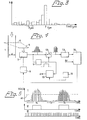
- the apparatus comprises two radiation detectors S1 and S2, which are spaced apart at a predetermined mutual distance L along the glass jet 1 and are arranged to receive, through a suitable optical system not shown in detail, radiation from two limited sections of the glass jet.
- these two limited sections of the glass jet are schematically illustrated by broken-line rectangles 2 and 3, respectively.
- these rectangles can be regarded as 'viewing windows' for the radiation detectors S1 and S2, respectively.
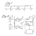
- Each of the detectors provides an electric output signal having, in principle, the form illustrated by way of example in Fig. 1. Although the major part of this signal has the nature of a noise signal, it also comprises a plurality of randomly occurring, pulse-like, large amplitude variations P.
- amplitude variations P are caused by randomly occurring, intensity variations of short duration in the radiation emitted by the glass jet 1.
- these intensity variations are most probably caused by randomly occurring air bubbles 4 in the glass material.
- an air bubble passes the viewing window 2 or 3, it causes a pulse-like amplitude variation P in the output signal from the associated detector S1 or S2, respectively, the magnitude of this amplitude variation being dependent inter alia on the size of the bubble and its distance from the external surface of the glass jet 1.
- the time of travel of a given air bubble from the upstream viewing window 2 to the downstream viewing window 3 will be equal to the time taken for the glass jet 1 to travel the distance L, wherefore it can be used for determining the flow velocity of the glass jet in accordance with the expression where V is the flow velocity and T is the travel time of the air bubble.
- Each of the output signals from the two detectors S1 and S2 are applied to a respective amplifying and signal-processing circuit F1 and F2.
- Each circuit F1 and F2 respectively, discriminates from the output signal of the associated radiation detector any pulse-like amplitude variations P having an amplitude exceeding a predetermined amplitude level, for instance the amplitude level A in Fig. 1, and provides on its output a corresponding signal pulse P' for each such amplitude variation P.
- a time measuring circuit R which may comprise a digital counter driven from a clock pulse generator C.
- the time measuring circuit R is started by an air bubble 4 in the glass jet 1 passing the viewing window 2 of the upstream detector S1, and is stopped again as soon thereafter as an air bubble 4 passes the viewing window 3 of the downstream detector S2.
- the time-measuring circuit R sends a ready signal to a calculating unit D, for instance comprising a micro-processor, which receives the measured value from the output of the time measuring circuit and at the same time resets said circuit.
- the time measuring circuit R is subsequently restarted as soon as an air bubble 4 passes the viewing window 2 for the upstream detector S1.
- the time measuring circuit R is started and stopped under the influence of precisely one and the same air bubble 4 in the glass jet 1. As will be understood, this will only be the case if there are no bubbles 4 present in the space between the viewing windows 2 and 3 at the time when a bubble passes the upstream window 2 and starts the time measuring circuit R. However, since the air bubbles 4 are completely randomly- located in the glass jet 1, in the majority of cases bubbles 4 will be present, in practice, between the windows 2 and 3 when the timing circuit R is started by a bubble 4 passing the window 2.
- the timing circuit R will be stopped prematurely by one of the bubbles already present between said windows 2 and 3, and hence the time interval measured by the timing circuit R will be too short. It may also be that the time interval measured by the timing circuit R is too long, for example when the bubble 4 which passes the upstream window 2 and initiates the timing circuit R does not, for some reason or other, pass the downstream window 3, e.g. because of irregular flow in the glass jet 1, and therewith does not influence the down- stream detector SZ. In this case, the time-measuring circuit R will be stopped by a later, subsequent bubble 4 and the time interval measured will be too long.
- the calculating unit D when practicing the invention, to obtain correct information concerning the «correct» time interval, i.e. the time taken for an air bubble 4, and therewith the glass jet 1, to travel the distance L between the viewing windows 2 and 3.
- this is effected in that the calculating unit D receives from the time-measuring circuit R, and stores a large number of time intervals, for example 100 time intervals, measured in the manner described above.
- the calculating unit D is designed or programmed to sort or classify these measured time intervals with respect to their values, and to determine the most frequently occurring value of theses measured time intervals received by and stored in the calculating unit.
- the calculating unit D sets up a histogram of the kind illustrated in Fig. 3, in which histogram the horizontal axis represents the values of the measured time intervals in classes or groups each having a width of X ⁇ s, and the vertical axis represents the number of measured time intervals N within each class or group. It is found that this histogram displays a single distinct peak or maximum for the class or group within which the correct time interval is located, i.e. the class or group having the center value Y ⁇ s in Fig. 3.
- the «erroneously» measured time intervals will be spread out along the time axis, mainly as too short time intervals, whereas all the correct measured time intervals will be placed at one and the same location along the time axis.
- This analysis of the measured time intervals received from the time measuring circuit 3 is performed automatically by the micro-processor in the calculating unit D, when this has received a predetermined number of measured time intervals, for instance 100.
- the calculating unit D could, per se, use the center value Y for the largest class of measured time intervals according to Fig. 3 as the wanted value of the travel time of the glass jet 1 over the distance L between the windows 2 and 3, and consequently calculate the flow velocity of the jet on the basis of this value in accordance with the expression given in the foregoing.
- the calculating unit D is designed and programmed in such a way that after having determined the value Y in the manner decribed above on the basis of a first plurality of measured time intervals, for instance 100, it accepts thereafter only such measured time intervals received from the time measuring circuit R as those which have values within a limited range on both sides of the value Y, i.e. within the range Y ⁇ Z%.
- the calculating unit D thereafter collects a predetermined number for instance 100, of such accepted measured time intervals and calculates the mean value of these accepted measured time intervals.
- This mean value is then regarded as the correct value of the travel time of the glass jet 1 over the distance L between the viewing windows 2 and 3.
- this mean value is updated, by calculating a new mean value for each new accepted measured time interval received from the time measuring circuit R, so that the mean value is always calculated on the basis of, for example the last hundred accepted measured time intervals received.
- the value Y is changed continuously, so as to be equal to the mean value last calculated, whereby the only measured time intervals arriving from the time measuring circuit R which will be accepted are those which have values within the range ⁇ Z% on both sides of the last calculated mean value.
- the measuring process will automatically follow the variations in the flow velocity of the glass jet 1.
- the calculating unit D will restart the process from the beginning, and establish a new histogram according to Fig. 3 in the manner described above, in order to find a correct value of Y. This may, for instance, be necessary in connection with very rapid changes in the flow velocity of the glass jet.
- the number of «accepted», i.e. correct, measured time intervals from the time measuring circuit R is at least about 8 to 10% of the total number of measured time intervals.
- This can be achieved by an appropriate selection of the distance L between the viewing windows 2 and 3, the size of the viewing windows and the magnitude of the threshold amplitude level A in the amplifiers F1 and F2 in relation to the number of air bubbles 4 present in the glass jet, and to the velocity of the glass jet, in such a manner that the mutual spacing, in time between mutually sequential signal pulses P' in each of the output signals from respective amplifiers F1 and F2 exceeds the travel time of the glass jet between the viewing windows 2 and 3 in at least about 8 to 10% of all cases.
- a larger threshold amplitude level A in the amplifiers F1 and F2 will reduce the number of signal pulses P' and consequently increase the mutual spacing in time between mutually sequential signal pulses P' for an unchanged total number of bubbles 4 in the glass jet and an unchanged flow velocity of the jet.
- an apparatus according to the invention can be further developed to determine not only the flow velocity of the material but also its volumetric flow rate, which is of interest in many fields of application, such as glass-fiber production, for example where it is important to be able to measure the volumetric rate of flow of the freely falling jet of molted glass down to the spinners. For this purpose it is necessary to determine the diameter of the jet, in addition to its flow velocity.
- the diameter of the glass jet can advantageously be measured by means of such an apparatus as that illustrated schematically in Fig. 4.
- This apparatus comprises a linear array of photodiodes 5, which throug a suitable optical system, not shown in detail in the drawing, is arranged to receive radiation emitted by the glass jet 1 along a line 6 which is perpendicular to the direction of flow of the glass jet. It will be appreciated that of the array 5 a number of diodes corresponding to the diameter dot the glass jet 1 will receive radiation from the jet 1, whereas the remaining diodes in the array will receive substantially only background radiation.
- the diodes in the array 5 are scanned or sensed periodically by means of a scanning circuit 7, from which a series of signal pulses are obtained with each scan, the number of pulses obtained being equal to the number of diodes in the array, and each of which signals has an amplitude corresponding to the amount of radiation received by the respective diode since the immediately preceding scan. Consequently, the output signal of the scanning circuit 7 has the form illustrated by the diagram 1 in Fig. 5.
- This diagram shows the output signal of the scanning circuit 7 for two mutually sequential scans, and the total scanning time for the array 5 is designated Ta, whereas the pause between two mutually sequential scans is designated To.
- the scanning or sampling frequency is consequently 1/Ta+To and is determined by a control circuit 8, which comprises, for instance, a voltage-controlled oscillator for determining the scanning frequency.
- the output signal of the scanning circuit 7 is applied to a digitizing circuit 9, which determines which pulses of the signal have an amplitude exceeding a predetermined level, for instance the amplitude level A1 in Fig. 5, and which produces a square wave signal of corresponding duration, i.e. having the shape illustrated by the diagram II in Fig. 5.
- This square wave signal thus has a duration corresponding to that number of diodes in the array 5 which have received radiation exceeding a given level A1.
- This square wave signal is applied to a time-measuring circuit 10, for instance in the form of a digital counter driven from a clock pulse generator 11, which counter is kept running by the square wave signal from the circuit 9 and which consequently counts a number of clock pulses corresponding to the duration of said square wave signal.
- the clock pulses from the clock pulse generator 11 are illustrated in the diagram III in Fig. 5.
- the resulting count in the digital counter of the time measuring circuit 10 will consequently constitute a measure of the diameter d of the glass jet 1, and is supplied from the time measuring circuit 10 to a calculating circuit, which also receives the measured value of the flow velocity of the glass jet 1 and which calculates the volumetric flow rate of the glass jet on the basis of these measured values.
- this measuring error is compensated for by applying the output signal of the scanning circuit 7 to a switch 12, which is controlled by the square wave signal from the circuit 9 in such a manner that it is closed only for the duration of this square wave signal, whereby only those output signals from the diodes of the array 5 which exceed the threshold level A1 are passed through the switch.
- These signals are applied to an averaging circuit 13 which determines the mean amplitude value of these signal pulses and supplies a corresponding signal to a control cicuit 14.
- this mean value signal from the circuit 13 is compared with a reference value Ar and in response to this comparison the control circuit 14 provides a control voltage to the voltage-controlled oscillator in the control circuit 8.
- the circuit 8 adjusts the scanning or sampling frequency for the array 5 in such a manner that the mean amplitude of the photodiode signals exceeding the threshold value A1 is maintained cosntant and equal to the reference amplitude Ar. It will be appreciated that this is possible, since the amplitude of the signal pulses from the diodes of the array 5 increases when the scanning or sampling period Ta+To increases, since each diode will then have time to receive a larger amount of radiation between each scan. In this way there is obtained an automatic compensation of the diameter measurement for any variations in the temperature of the glass jet 1, and thus in its radiation intensity.
- the photodiode array 5 is preferably located between the two radiation detectors S1 and S2, whereby the velocity and the diameter will be measured at substantially the same location along the material flow.
Landscapes
- Physics & Mathematics (AREA)
- General Physics & Mathematics (AREA)
- Fluid Mechanics (AREA)
- Engineering & Computer Science (AREA)
- Aviation & Aerospace Engineering (AREA)
- Measuring Volume Flow (AREA)
- Analysing Materials By The Use Of Radiation (AREA)
- Investigating Or Analyzing Materials Using Thermal Means (AREA)
- Prostheses (AREA)
- Materials For Medical Uses (AREA)
- Investigating Materials By The Use Of Optical Means Adapted For Particular Applications (AREA)
Claims (12)
Priority Applications (1)
| Application Number | Priority Date | Filing Date | Title |
|---|---|---|---|
| AT83850142T ATE21771T1 (de) | 1982-06-11 | 1983-05-24 | Verfahren und vorrichtung zum bestimmen der fliessgeschwindigkeit eines geschmolzenen, strahlung aussendenden materials. |
Applications Claiming Priority (2)
| Application Number | Priority Date | Filing Date | Title |
|---|---|---|---|
| SE8203650 | 1982-06-11 | ||
| SE8203650A SE431030C (sv) | 1982-06-11 | 1982-06-11 | Sett och anordning for bestemning av stromningshastigheten hos en strale av smelt glas |
Publications (3)
| Publication Number | Publication Date |
|---|---|
| EP0100304A1 EP0100304A1 (de) | 1984-02-08 |
| EP0100304B1 true EP0100304B1 (de) | 1986-08-27 |
| EP0100304B2 EP0100304B2 (de) | 1990-03-14 |
Family
ID=20347050
Family Applications (1)
| Application Number | Title | Priority Date | Filing Date |
|---|---|---|---|
| EP83850142A Expired - Lifetime EP0100304B2 (de) | 1982-06-11 | 1983-05-24 | Verfahren und Vorrichtung zum Bestimmen der Fliessgeschwindigkeit eines geschmolzenen, Strahlung aussendenden Materials |
Country Status (10)
| Country | Link |
|---|---|
| EP (1) | EP0100304B2 (de) |
| JP (1) | JPS59501027A (de) |
| AT (1) | ATE21771T1 (de) |
| AU (1) | AU569202B2 (de) |
| DE (1) | DE3365619D1 (de) |
| DK (1) | DK61384A (de) |
| FI (1) | FI69519C (de) |
| NO (1) | NO840502L (de) |
| SE (1) | SE431030C (de) |
| WO (1) | WO1983004437A1 (de) |
Families Citing this family (9)
| Publication number | Priority date | Publication date | Assignee | Title |
|---|---|---|---|---|
| FR2667689B1 (fr) * | 1990-10-04 | 1994-08-05 | Saint Gobain Isover | Mesure du debit d'un filet de materiau fondu. |
| US5170438A (en) * | 1991-03-22 | 1992-12-08 | Graham Fiber Glass Limited | Method and apparatus for determining the flow rate of a viscous fluid stream |
| DK0632274T3 (da) * | 1993-07-02 | 1998-02-09 | Waertsilae Nsd Schweiz Ag | Indretning og installationsdel til måling af hastigheden for en roterende luftstrøm i en motors cylinder |
| DE4412494C2 (de) * | 1994-04-12 | 1997-02-27 | Kugelstrahlzentrum Aachen Gmbh | Verfahren zur Messung der Geschwindigkeitsverteilung eines Strahlmittelstromes |
| AT1157U1 (de) * | 1995-12-15 | 1996-11-25 | Avl Verbrennungskraft Messtech | Verfahren zur optischen messung von gasblasen in einer kühlflüssigkeit |
| FR2761455B1 (fr) | 1997-03-28 | 1999-05-14 | Bio Merieux | Procede et dispositif pour le controle de flux liquides dans des reseaux de canalisations |
| RU2170438C2 (ru) * | 1999-09-03 | 2001-07-10 | Растопов Станислав Федорович | Способ измерения скорости потока и устройство для его осуществления |
| EP1102041A1 (de) | 1999-11-20 | 2001-05-23 | Reto T. Meili | Messverfahren und Messsystem zum Ausführen des Messverfahrens |
| EP4449092A1 (de) | 2021-12-17 | 2024-10-23 | Saint-Gobain Isover | Verfahren und system zur messung der kinematischen viskosität eines freien fluidstroms |
Family Cites Families (15)
| Publication number | Priority date | Publication date | Assignee | Title |
|---|---|---|---|---|
| GB1132364A (en) * | 1965-03-24 | 1968-10-30 | Licentia Gmbh | Improvements relating to the contactless measurement of the speed of strip |
| US3388328A (en) * | 1965-06-10 | 1968-06-11 | Koppers Co Inc | Pulsed laser system for relative speed measurement |
| US3455143A (en) * | 1966-10-31 | 1969-07-15 | Exxon Research Engineering Co | Calibration and proving of meters |
| LU61023A1 (de) * | 1970-05-29 | 1971-08-12 | ||
| US3739636A (en) * | 1971-01-22 | 1973-06-19 | A Versaci | Linear readout flowmeter |
| US3818231A (en) * | 1971-07-20 | 1974-06-18 | Westinghouse Electric Corp | N-16 nuclear reactor coolant flow rate measuring system |
| GB1439324A (en) * | 1972-10-17 | 1976-06-16 | British Steel Corp | Gas flow measurements |
| US3941477A (en) * | 1974-10-17 | 1976-03-02 | Deutsche Forschungs-Und Versuchsanstalt Fur Luft-Und Raumfahrt E.V. | Measuring device for the measurement of fluid flow rates |
| DE2616443B2 (de) * | 1976-04-14 | 1978-02-09 | Grünzweig + Hartmann und Glasfaser AG, 6700 Ludwigshafen | Verfahren zur beruehrungslosen laengen- bzw. geschwindigkeitsmessung eines sich bewegenden bandes |
| SU646258A1 (ru) * | 1977-04-27 | 1979-02-05 | Предприятие П/Я Р-6729 | Способ измерени скорости движени газовых пузырей в газожидкостном потоке |
| JPS54133387A (en) * | 1978-04-08 | 1979-10-17 | Nippon Kokan Kk | Method and device for measuring velocity of highhtemperature fluid |
| DE2910018A1 (de) * | 1979-03-14 | 1980-09-18 | Peter Dipl Ing Glasmacher | Blasenaufstiegsmessung |
| DE2912628A1 (de) * | 1979-03-30 | 1980-10-02 | Peter Dipl Ing Glasmacher | Blasenaufstiegsmessung |
| JPS56124019A (en) * | 1980-03-05 | 1981-09-29 | Yokogawa Hokushin Electric Corp | Interrelated type flow meter |
| SE431029C (sv) * | 1980-12-16 | 1986-10-20 | Gedevelop Ab | Forfarande och anordning for metning av stromningshastigheten hos en strale av smelt glas |
-
1982
- 1982-06-11 SE SE8203650A patent/SE431030C/sv not_active IP Right Cessation
-
1983
- 1983-05-24 DE DE8383850142T patent/DE3365619D1/de not_active Expired
- 1983-05-24 EP EP83850142A patent/EP0100304B2/de not_active Expired - Lifetime
- 1983-05-24 WO PCT/SE1983/000206 patent/WO1983004437A1/en not_active Ceased
- 1983-05-24 AT AT83850142T patent/ATE21771T1/de not_active IP Right Cessation
- 1983-05-24 JP JP58502012A patent/JPS59501027A/ja active Pending
- 1983-05-24 AU AU16044/83A patent/AU569202B2/en not_active Expired
-
1984
- 1984-02-10 FI FI840550A patent/FI69519C/fi not_active IP Right Cessation
- 1984-02-10 NO NO840502A patent/NO840502L/no unknown
- 1984-02-10 DK DK61384A patent/DK61384A/da not_active Application Discontinuation
Also Published As
| Publication number | Publication date |
|---|---|
| NO840502L (no) | 1984-02-10 |
| FI69519C (fi) | 1986-02-10 |
| FI69519B (fi) | 1985-10-31 |
| AU1604483A (en) | 1983-12-30 |
| SE431030B (sv) | 1983-12-27 |
| SE8203650L (sv) | 1983-12-12 |
| EP0100304B2 (de) | 1990-03-14 |
| FI840550A0 (fi) | 1984-02-10 |
| AU569202B2 (en) | 1988-01-21 |
| JPS59501027A (ja) | 1984-06-07 |
| FI840550A7 (fi) | 1984-02-10 |
| DE3365619D1 (en) | 1986-10-02 |
| SE431030C (sv) | 1986-10-20 |
| DK61384D0 (da) | 1984-02-10 |
| DK61384A (da) | 1984-02-10 |
| ATE21771T1 (de) | 1986-09-15 |
| WO1983004437A1 (en) | 1983-12-22 |
| EP0100304A1 (de) | 1984-02-08 |
Similar Documents
| Publication | Publication Date | Title |
|---|---|---|
| US4318483A (en) | Automatic relative droplet charging time delay system for an electrostatic particle sorting system using a relatively moveable stream surface sensing system | |
| EP0100304B1 (de) | Verfahren und Vorrichtung zum Bestimmen der Fliessgeschwindigkeit eines geschmolzenen, Strahlung aussendenden Materials | |
| US4318482A (en) | Method for measuring the velocity of a perturbed jetting fluid in an electrostatic particle sorting system | |
| US4325483A (en) | Method for detecting and controlling flow rates of the droplet forming stream of an electrostatic particle sorting apparatus | |
| US4635215A (en) | Article or seed counter | |
| US4318480A (en) | Method and apparatus for positioning the point of droplet formation in the jetting fluid of an electrostatic sorting device | |
| JP2008122395A (ja) | In−Situ走査ビームの粒子モニタのための信号処理方法 | |
| US4510438A (en) | Coincidence correction in particle analysis system | |
| US4517845A (en) | Method and apparatus for determining the flow velocity of a molten, radiation-emitting material | |
| US4409012A (en) | Method and apparatus for monitoring a glass furnace | |
| EP0054532B1 (de) | Vorrichtung zum Messen der Strömungsgeschwindigkeit von geschmolzenem Material | |
| IE53171B1 (en) | Method and apparatus for determining the flow velocity of a molten,radiation-emitting material | |
| CA1178081A (en) | Method and apparatus for determining the flow velocity of a molten, radiation-emitting material | |
| NZ200966A (en) | Measuring flow velocity of molten radiation emitting material | |
| US4697925A (en) | Method of measurement using scattered light | |
| US4177482A (en) | Population and profile data of bodies in a transparent mass | |
| JPS6359442B2 (de) | ||
| JP2821607B2 (ja) | 粒数計数装置 | |
| JPS6041722B2 (ja) | 表面位置検出装置 | |
| SU1509135A1 (ru) | Способ настройки радиометрического сепаратора покусковой сортировки минерального сырь | |
| SU598315A1 (ru) | Устройство дл контрол реологи-чЕСКиХ СВОйСТВ СТЕКлОМАССы | |
| JPH03130672A (ja) | トナー帯電量分布測定装置 | |
| JPH03163314A (ja) | 血液量計測装置 |
Legal Events
| Date | Code | Title | Description |
|---|---|---|---|
| PUAI | Public reference made under article 153(3) epc to a published international application that has entered the european phase |
Free format text: ORIGINAL CODE: 0009012 |
|
| AK | Designated contracting states |
Designated state(s): AT BE CH DE FR GB IT LI LU NL |
|
| 17P | Request for examination filed |
Effective date: 19840802 |
|
| RAP1 | Party data changed (applicant data changed or rights of an application transferred) |
Owner name: GEDEVELOP AKTIEBOLAG |
|
| GRAA | (expected) grant |
Free format text: ORIGINAL CODE: 0009210 |
|
| AK | Designated contracting states |
Kind code of ref document: B1 Designated state(s): AT BE CH DE FR GB IT LI LU NL |
|
| REF | Corresponds to: |
Ref document number: 21771 Country of ref document: AT Date of ref document: 19860915 Kind code of ref document: T |
|
| ITF | It: translation for a ep patent filed | ||
| REF | Corresponds to: |
Ref document number: 3365619 Country of ref document: DE Date of ref document: 19861002 |
|
| ET | Fr: translation filed | ||
| PLBI | Opposition filed |
Free format text: ORIGINAL CODE: 0009260 |
|
| 26 | Opposition filed |
Opponent name: DEUTSCHE FORSCHUNGS- UND VERSUCHSANSTALT FUER LUFT Effective date: 19870130 |
|
| NLR1 | Nl: opposition has been filed with the epo |
Opponent name: DEUTSCHE FORSCH.-UND VERSUCHSANST. FUER LUFT- UND |
|
| PG25 | Lapsed in a contracting state [announced via postgrant information from national office to epo] |
Ref country code: LU Free format text: LAPSE BECAUSE OF NON-PAYMENT OF DUE FEES Effective date: 19870531 |
|
| PUAH | Patent maintained in amended form |
Free format text: ORIGINAL CODE: 0009272 |
|
| STAA | Information on the status of an ep patent application or granted ep patent |
Free format text: STATUS: PATENT MAINTAINED AS AMENDED |
|
| ITF | It: translation for a ep patent filed | ||
| 27A | Patent maintained in amended form |
Effective date: 19900314 |
|
| AK | Designated contracting states |
Kind code of ref document: B2 Designated state(s): AT BE CH DE FR GB IT LI LU NL |
|
| ET3 | Fr: translation filed ** decision concerning opposition | ||
| NLR2 | Nl: decision of opposition | ||
| NLR3 | Nl: receipt of modified translations in the netherlands language after an opposition procedure | ||
| ITTA | It: last paid annual fee | ||
| PGFP | Annual fee paid to national office [announced via postgrant information from national office to epo] |
Ref country code: AT Payment date: 19960514 Year of fee payment: 14 |
|
| PGFP | Annual fee paid to national office [announced via postgrant information from national office to epo] |
Ref country code: CH Payment date: 19960606 Year of fee payment: 14 |
|
| PG25 | Lapsed in a contracting state [announced via postgrant information from national office to epo] |
Ref country code: AT Effective date: 19970524 |
|
| PG25 | Lapsed in a contracting state [announced via postgrant information from national office to epo] |
Ref country code: LI Free format text: LAPSE BECAUSE OF NON-PAYMENT OF DUE FEES Effective date: 19970531 Ref country code: CH Free format text: LAPSE BECAUSE OF NON-PAYMENT OF DUE FEES Effective date: 19970531 |
|
| REG | Reference to a national code |
Ref country code: CH Ref legal event code: PL |
|
| REG | Reference to a national code |
Ref country code: GB Ref legal event code: IF02 |
|
| PGFP | Annual fee paid to national office [announced via postgrant information from national office to epo] |
Ref country code: FR Payment date: 20020430 Year of fee payment: 20 |
|
| PGFP | Annual fee paid to national office [announced via postgrant information from national office to epo] |
Ref country code: GB Payment date: 20020507 Year of fee payment: 20 |
|
| PGFP | Annual fee paid to national office [announced via postgrant information from national office to epo] |
Ref country code: NL Payment date: 20020514 Year of fee payment: 20 |
|
| PGFP | Annual fee paid to national office [announced via postgrant information from national office to epo] |
Ref country code: BE Payment date: 20020517 Year of fee payment: 20 |
|
| PGFP | Annual fee paid to national office [announced via postgrant information from national office to epo] |
Ref country code: DE Payment date: 20020522 Year of fee payment: 20 |
|
| PG25 | Lapsed in a contracting state [announced via postgrant information from national office to epo] |
Ref country code: GB Free format text: LAPSE BECAUSE OF EXPIRATION OF PROTECTION Effective date: 20030523 |
|
| PG25 | Lapsed in a contracting state [announced via postgrant information from national office to epo] |
Ref country code: NL Free format text: LAPSE BECAUSE OF EXPIRATION OF PROTECTION Effective date: 20030524 |
|
| BE20 | Be: patent expired |
Owner name: *GEDEVELOP A.B. Effective date: 20030524 |
|
| REG | Reference to a national code |
Ref country code: GB Ref legal event code: PE20 |
|
| NLV7 | Nl: ceased due to reaching the maximum lifetime of a patent |
Effective date: 20030524 |
|
| PLAB | Opposition data, opponent's data or that of the opponent's representative modified |
Free format text: ORIGINAL CODE: 0009299OPPO |
|
| PLAB | Opposition data, opponent's data or that of the opponent's representative modified |
Free format text: ORIGINAL CODE: 0009299OPPO |
|
| R26 | Opposition filed (corrected) |
Opponent name: DEUTSCHE FORSCHUNGS- UND VERSUCHSANSTALT FUER LUFT Effective date: 19870130 |