EP0100212A2 - Luftgekühlte Eisbahnkonstruktion - Google Patents
Luftgekühlte Eisbahnkonstruktion Download PDFInfo
- Publication number
- EP0100212A2 EP0100212A2 EP83304245A EP83304245A EP0100212A2 EP 0100212 A2 EP0100212 A2 EP 0100212A2 EP 83304245 A EP83304245 A EP 83304245A EP 83304245 A EP83304245 A EP 83304245A EP 0100212 A2 EP0100212 A2 EP 0100212A2
- Authority
- EP
- European Patent Office
- Prior art keywords
- air
- ice
- chamber
- flow channel
- ice rink
- Prior art date
- Legal status (The legal status is an assumption and is not a legal conclusion. Google has not performed a legal analysis and makes no representation as to the accuracy of the status listed.)
- Granted
Links
Images


Classifications
-
- F—MECHANICAL ENGINEERING; LIGHTING; HEATING; WEAPONS; BLASTING
- F25—REFRIGERATION OR COOLING; COMBINED HEATING AND REFRIGERATION SYSTEMS; HEAT PUMP SYSTEMS; MANUFACTURE OR STORAGE OF ICE; LIQUEFACTION SOLIDIFICATION OF GASES
- F25C—PRODUCING, WORKING OR HANDLING ICE
- F25C3/00—Processes or apparatus specially adapted for producing ice or snow for winter sports or similar recreational purposes, e.g. for sporting installations; Producing artificial snow
- F25C3/02—Processes or apparatus specially adapted for producing ice or snow for winter sports or similar recreational purposes, e.g. for sporting installations; Producing artificial snow for ice rinks
-
- E—FIXED CONSTRUCTIONS
- E01—CONSTRUCTION OF ROADS, RAILWAYS, OR BRIDGES
- E01C—CONSTRUCTION OF, OR SURFACES FOR, ROADS, SPORTS GROUNDS, OR THE LIKE; MACHINES OR AUXILIARY TOOLS FOR CONSTRUCTION OR REPAIR
- E01C13/00—Pavings or foundations specially adapted for playgrounds or sports grounds; Drainage, irrigation or heating of sports grounds
- E01C13/10—Pavings or foundations specially adapted for playgrounds or sports grounds; Drainage, irrigation or heating of sports grounds for artificial surfaces for outdoor or indoor practice of snow or ice sports
- E01C13/102—Civil engineering aspects of the construction of ice rinks or sledge runs made from frozen-liquid, semi-liquid or frozen-pasty substances, e.g. portable basins
- E01C13/105—Civil engineering aspects of the construction of ice rinks or sledge runs made from frozen-liquid, semi-liquid or frozen-pasty substances, e.g. portable basins of artificially refrigerated rinks or runs, e.g. cooled rink floors or swimming pools or tennis courts convertible into rinks
Definitions
- This invention relates to an ice rink cooling system, and more particularly, to a cooling system utilizing circulated cold air.
- the conventional type of artificial cooling for enclosed ice rinks generally comprises an array of cooling coils encased within the concrete slab of the ice rink.
- a brine solution is circulated through the coils, heat being continuously removed from the brine solution by heat exchange * with the Freon or ammonia of the refrigeration plant. If extended end-to-end, the pipes of the cooling coils would be several miles in length.
- the slab of most conventional ice rinks is maintained at approximately 18°F.; it has been found that this temperature represents an optimum compromise between the power consumed by the refrigeration plant and the maintenance of a suitable ice quality.
- An underlay of insulation may exist in the cavity between the ice rink slab and the underlying ground, either occupying the whole of such cavity or an upper or lower portion only of such cavity. Such insulation, whether it partially or fully fills the cavity under the ice rink slab, has little effect on the amount of heat drawn by the ice rink slab from the ground.
- the ice rink slab may be supported above the ground by supports which partition the space under the ice rink slab into a series of small cavities all isolated from each other as well as from the ambient temperature conditions of air external to the ice rink enclosure.
- the ground may take two or three months to thaw after cooling of the ice rink slab is discontinued, the ice rink enclosure being maintained at an abnormally low temperature during such time by such thawing.
- the subject invention is a means for cooling an ice rink that has the advantages of both simplicity and lower operating costs over the cooling means utilized in a conventional ice rink construction such as that described in the foregoing paragraphs.
- the ice rink construction of the subject invention has a further advantage over those conventional ice rinks that are constructed with the slab resting directly on the ground (as opposed to being supported off the ground).
- the further advantage is that the subject inventicn virtually eliminates "slab failure" due to settlement or frost heave.
- Slab failure refers to cracking of a slab resulting from localised stresses on the slab due to shifting of the ground on which it directly rests. Brine pipe breakage and leakage usually accompany slab failure, and the cost of repairing or replacing an ice rink slab are considerable.
- slab failure In one eastern region of Canada slab failure is present to some degree in more than 50% of the ice rinks in which the slab rests directly on the ground. As will become evident, slab failure would be almost impossible with the ice rink construction of the subject invention.
- a still further advantage of the ice rink construction of the subject invention relates to the significantly faster rate at which ice may be cooled compared to that possible in a conventional ice rink construction.
- the ice temperature in all ice rinks is normally allowed to rise to approximately 28°F. during the periods that the ice rink structure is unoccupied.
- the ice rink construction of the subject invention can cool ice from such temperature to a temperature suitable for skating (normally, approximately 18°F.) at a significantly faster rate than is possible with a conventional ice rink construction. In localities where off-peak reduced electrical rates are applicable, such faster ice cooling ability may provide the subject invention with an even greater economic advantage over conventional systems.
- the subject invention is an ice rink construction comprising a floor adapted to support ice thereon, and a cooling means adapted to cool the floor.
- the cooling means is supported off the ground such that ambient external air has access to the region between the cooling means and the ground and insulation extends between the cooling means and such region.
- the subject invention is an ice rink construction
- a floor adapted to support ice thereon
- a chamber extending under the floor such that the floor defines an upper surface of the chamber, all surfaces of the chamber except the upper surface being insulated against heat transfer, and means adapted to circulate cold air through the chamber at a rate sufficient to maintain freezing of ice on the floor.
- the ice rink construction of the subject invention is also defined by the chamber being supported off the ground such that ambient external air has access to the region under the chamber.
- Canadian Patent No. 922,526 relates to an air-cooled artificial ice rink in which cooled air is circulated through the hollow space between the ice supporting surface of an ice rink and the ground thereunder.
- the ice supporting surface is supported above the ground such that a single cavity extends under the whole ice supporting surface.
- Air circulates generally through the hollow space and through the cooling coil of a refrigeration unit positioned under the ice supporting surface.
- the ice rink construction of the reference has the drawback of conventional brine-Freon ice rink cooling plants in that heat is drawn from the ground under the ice rink by the cooling medium.
- the subject invention differs from such ice rink cooling means by allowing ambient external air access to the region under the cooling means, such region being separated from the cooling means by insulation.
- the ice rink slab of the subject invention draws heat from the ice but not from the ground; the ground is exposed to ambient external air conditions.
- An advantage of the ice rink cooling means of the subject invention is that ambient external air, when sufficiently low in temperature, can be circulated through the chamber under the ice rink slab.
- a control means selectively controls whether ambient external air is circulated through that chamber or whether air cooled by the refrigeration unit is recirculated through the chamber.
- the control means is connected to a sensor exposed to the ambient external air conditions.
- a fan means circulates the air through the circulating flow channel.
- a cooling means in the circulating flow channel is operable to remove heat from the air being t circulated through that channel.
- Ambient external air is introduced into and expelled from the circulating flow channel by means of a pair of dampers spaced from each other along that channel.
- the means for selectively controlling whether ambient external air is circulated through the circulating flow channel operates the pair of dampers and also operates a further damper positioned in the circulating flow channel intermediate of the pair of dampers.
- Chamber 10 comprises a portion of the circulating flow channel of the subject invention.
- the other parts of the circulating flow channel are insulated duct 12 and the ducts within refrigeration plant 33.
- Refrigeration plant 13 receives air flowing out of insulated duct 12 and cools that air before sending it back into chamber 10.
- the air leaving insulated duct 12 may be directed out of the circulating flow channel through damper 14 and an equivalent amount of ambient external air may be induced into the circulating flow channel through damper 15.
- the air flowing through the circulating flow channel comprises recirculated mechanically-cooled air or comprises circulated cold ambient external air
- an automatic control means (not shown) which automatically opens and closes dampers 14 and 15 and correspondingly closes and opens a third damper 16 which is positioned in the circulating flow channel intermediate of dampers 14 and 15.
- Air is circulated through the circulating flow channel by means of a fan 17 located within refrigeration plant 13.
- a cooling coil 18 of a refrigeration unit (not shown) is positioned in the circulating flow channel intermediate of damper 16 and the position where damper 15 allows air inflow.
- a perforated partition is located at each end of chamber 10 such that air flow through the circulating flow channel is generally evenly distributed across chamber 10.
- the upstream partition is designated as 20 in Figure 1 and the downstream partition is designated as 21.
- the perforation size in the partitions increases with the separation distance from fan 17 to create the even air flow distribution.
- Also shown in Figure 1 in outline are the rounded corners of the ice surface positioned above'chamber 10. As previously mentioned, all of the surfaces of the circulating flow channel are insulated except for the ice rink slab which is thereby cooled to a temperature sufficiently low that the temperature of the Jce resting thereon is maintained at the desired design tempera-cure for skating, usually approximately 18°F.
- Such ice temperature is maintained by a control means which can modify the quantity of coolant in coil 18 and vary the rotational speed of fan 17.
- a control means which can modify the quantity of coolant in coil 18 and vary the rotational speed of fan 17.
- an ice temperature of 18°F. is a compromise between the power required of the refrigeration unit and an ice temperature sufficiently low to be suitable for skating. This assumes that the ambient external air is at too high a temperature to remove heat from the ice rink slab if circulated through the circulating flow channel; in such case, the dampers 14 and 15 are fully closed and all air in the circulating flow channel is air recirculated through damper 16 of the refrigeration plant. If, however, the ambient external air is at a temperature of approximately 16°F.
- dampers 14 and 15 it is worthwhile to fully open dampers 14 and 15, to correspondingly fully close damper 16, and to turn off the refrigeration unit connected to cooling coil 18.
- fan 17 will still continue to operate to induce ambient external air into the circulating flow channel at damper 15, move it thrcugh the path of the circulating flow channel, and expel it from the circulating flow channel at damper 14.
- the ice of the ice rink is cooled to only 18°F. when cooling coil 18 is utilized to remove heat from the circulating air, it should be clear that the ice can be cooled to temperatures lower than 18°F. if the ambient external air is instead utilized and is below approximately 16°F. In such case, the ice will attain a steady state condition at the reduced temperature and no futher cooling will be necessary until the ice temperature has increased back to 18°F.
- Such "stored cooling” results in a further reduction in operating costs.
- Figures 2 and 3 are cross-sectional end views of two embodiments of ice rink constructions utilizing the subject invention. The invention should, however, in no way be construed as limited by the embodiments to be described.
- the ice rink construction of Figure 2 is a row of parallel I-beams 30 supporting a series of braced floor sections 31 which carry a metal deck 32 and a poured concrete slab 33 thereabove.
- the metal deck and poured concrete overlay of the ice rink portion of the arena is generally of lighter construction than the remaining portion of the arena floor; this is clearly shown in Figure 2.
- the braced floor sections 31 each have a bottom member 34 to which is secured panelling . 35.
- Such construction creates chambers 36 under the floor of the arena, each chamber 36 extending longitudinally in the arena between neighboring pairs of I-beams 30.
- Insulation 37 extends along the lower surface of the chambers 36 and also extends up the surface of the I-beams that are positioned under the sideboards of the ice rink.
- the chamber 36 that is located under the non-ice rink portion of the floor of the arena and adjacent to the ice rink portion of the arena is insulated on its upper, lower and side surfaces so as to act as the insulated duct 12 which returns circulating air to the refrigeration plant.
- spacers 38 are attached to the bottom member 34 of each floor support section 31 and also to the bottom of I-beams 30, the panelling 35 being secured to the bottom of the spacers 38. Insulation is placed on panelling 35 to the depth of the spacers 38.
- the boards delineating the sides of the ice rink the boards being designated as 39.
- Figure 4 The floor support construction of Figure 2 is that utilized n Figure 4.
- an ice rink arena has been shown in cross-section, a lower level of the arena housing a parking garage and the upper level housing an ice rink and the other arena facilities such as a viewing stand for the audience.
- FIG. 3 An alternate embodiment of an ice rink construction utilizing the subject invention is shown in Figure 3.
- a series of parallel concrete block foundation walls 40 supports a floor 41 comprising a concrete slab on a metal deck. Positioned on the floor 41 directly above each concrete block wall 40 is an additional height of wall designated in Figure 3 as 42.
- a floor 43 also comprising a concrete slab on a metal deck, rests on the upper block walls 42.
- insulation extends along the bottom surface and side surfaces of the chamber immediately under the ice rink.
- the duct that carries return air to the refrigeration plant is insulated on all four of its sides.
- the air space 45 has a depth defined by the distance by which foundation walls 40 extend above the surface of the ground; that depth must be sufficient that ambient external air can freely circulate into the air space from either end of the arena. In this regard, it should be stressed that it is desirable during normal operation that no barriers be placed along the lower walls of the arena and that ambient external air be allowed access into the air space under the arena and adjacent to the ground.
- FIGS 2 and 3 are only two of the possible ice rink constructions in which the subject invention might be utilized. 'It should be clear to one skilled in ice rink construction that other structural arrangements could be utilized. For instance, steel plate supported on a space frame could be utilized in place of a concrete slab to support the ice surface; in such case, the ice thickness could be approximately double that in conventional ice rinks, thus providing another type of "stored cooling" and attendant reduced operating costs.
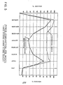
- Figure 5 illustrates the estimated savings that may be effected in annual power consumption by utilizing the air-cooled freezer deck system of the subject invention rather than a conventional Freon-brine system.
- Maximum power consumption occurs during October, and it can be seen that the maximum power consumption of the cooling system of the subject invention is only 90% of that of the conventional system.
- the power consumption of the cooling system of the subject invention is dramatically lower than that of the conventional system due to two factors. The first factor is that ambient external air is utilized for ground cooling and the second factor is that ambient external air can be utilized in the circulating flow channel to reduce the operating cost of the refrigeration plant.
- the subject invention is not restricted in its application to new ice rink construction only but is also applicable to existent ice rink structures having failed slabs. Such slabs need not necessarily be removed prior to installation of the cooling system of the subject invention, but can instead in certain cases be incorporated into that cooling system. If the old slab was mounted above an air cavity to which ambient external air can be given access, the old slab can be utilized as the base of an air flow chamber having a new slab as its cover. In this construction, the new ice surface would be approximately sixteen inches higher than the old ice surface which might necessitate removal of the front row of seating and raising of the sideboards, but the reduced operating costs should more than compensate for such renovations.
Landscapes
- Engineering & Computer Science (AREA)
- Physics & Mathematics (AREA)
- Thermal Sciences (AREA)
- General Engineering & Computer Science (AREA)
- Architecture (AREA)
- Civil Engineering (AREA)
- Structural Engineering (AREA)
- Mechanical Engineering (AREA)
- Road Paving Structures (AREA)
- Central Air Conditioning (AREA)
Priority Applications (1)
| Application Number | Priority Date | Filing Date | Title |
|---|---|---|---|
| AT83304245T ATE28343T1 (de) | 1982-07-26 | 1983-07-21 | Luftgekuehlte eisbahnkonstruktion. |
Applications Claiming Priority (2)
| Application Number | Priority Date | Filing Date | Title |
|---|---|---|---|
| CA408052 | 1982-07-26 | ||
| CA000408052A CA1153902A (en) | 1982-07-26 | 1982-07-26 | Air cooled ice rink construction |
Publications (3)
| Publication Number | Publication Date |
|---|---|
| EP0100212A2 true EP0100212A2 (de) | 1984-02-08 |
| EP0100212A3 EP0100212A3 (en) | 1984-12-05 |
| EP0100212B1 EP0100212B1 (de) | 1987-07-15 |
Family
ID=4123287
Family Applications (1)
| Application Number | Title | Priority Date | Filing Date |
|---|---|---|---|
| EP83304245A Expired EP0100212B1 (de) | 1982-07-26 | 1983-07-21 | Luftgekühlte Eisbahnkonstruktion |
Country Status (5)
| Country | Link |
|---|---|
| US (1) | US4513583A (de) |
| EP (1) | EP0100212B1 (de) |
| AT (1) | ATE28343T1 (de) |
| CA (1) | CA1153902A (de) |
| DE (1) | DE3372509D1 (de) |
Cited By (1)
| Publication number | Priority date | Publication date | Assignee | Title |
|---|---|---|---|---|
| RU2464376C1 (ru) * | 2011-04-07 | 2012-10-20 | Валентин Иванович Зверховский | Способ создания воздушной завесы над поверхностью льда в конькобежных центрах |
Families Citing this family (8)
| Publication number | Priority date | Publication date | Assignee | Title |
|---|---|---|---|---|
| US4634315A (en) * | 1985-08-22 | 1987-01-06 | Terra Tek, Inc. | Forced refreezing method for the formation of high strength ice structures |
| NO307142B1 (no) * | 1998-06-02 | 2000-02-14 | Voelstad Energy As | Stadionanlegg med arena så som en isbane, og omkringliggende tribune for publikum, samt kanalelement for kanalsystem i stadionanlegg så som en isbane, og omkringliggende tribune for publikum |
| US6021646A (en) * | 1998-06-26 | 2000-02-08 | Burley's Rink Supply, Inc. | Floor system for a rink |
| US6672083B2 (en) * | 2001-07-18 | 2004-01-06 | Steve Mildengren | Integrated mini ice sheets |
| CA2443014C (en) * | 2003-09-26 | 2008-10-28 | Murray Beynon | Ice skating arena |
| SE531981C2 (sv) * | 2006-05-08 | 2009-09-22 | Munters Europ Ab | Förfarande för minskning av fukthalten hos luft i ett avgränsat utrymme |
| KR101937381B1 (ko) * | 2017-05-18 | 2019-01-10 | 한국외국어대학교 연구산학협력단 | 빙상 트랙 운용을 위한 돔 시스템 |
| RU2694720C1 (ru) * | 2018-01-22 | 2019-07-16 | Лариса Викторовна Тельманова | Способ энергосбережения при производстве искусственного холода для ледовых арен |
Family Cites Families (7)
| Publication number | Priority date | Publication date | Assignee | Title |
|---|---|---|---|---|
| US632035A (en) * | 1899-02-18 | 1899-08-29 | Andrew Greig Anderson | Ice floor for skating-rinks, &c. |
| US1053443A (en) * | 1909-07-23 | 1913-02-18 | Dudley H Scott | Method of making and maintaining ice in skating-rinks. |
| GB191101314A (en) * | 1910-01-19 | 1911-02-02 | Leo Galland | Improvements in Artificial Ice Skating Floors. |
| DE1953591A1 (de) * | 1969-10-24 | 1971-05-06 | Siegfried Kuebler | Kuenstliche Eisflaeche mit Luft als Kaeltetraeger |
| US3641782A (en) * | 1970-06-01 | 1972-02-15 | American Air Filter Co | Ice skating rink |
| US3658124A (en) * | 1970-08-06 | 1972-04-25 | Joseph R Tippmann | Air operated ice rink |
| US4023947A (en) * | 1976-01-27 | 1977-05-17 | Ferry Everett B | Ambient air assist for a refrigerator unit |
-
1982
- 1982-07-26 CA CA000408052A patent/CA1153902A/en not_active Expired
-
1983
- 1983-06-06 US US06/501,247 patent/US4513583A/en not_active Expired - Fee Related
- 1983-07-21 AT AT83304245T patent/ATE28343T1/de not_active IP Right Cessation
- 1983-07-21 EP EP83304245A patent/EP0100212B1/de not_active Expired
- 1983-07-21 DE DE8383304245T patent/DE3372509D1/de not_active Expired
Cited By (1)
| Publication number | Priority date | Publication date | Assignee | Title |
|---|---|---|---|---|
| RU2464376C1 (ru) * | 2011-04-07 | 2012-10-20 | Валентин Иванович Зверховский | Способ создания воздушной завесы над поверхностью льда в конькобежных центрах |
Also Published As
| Publication number | Publication date |
|---|---|
| US4513583A (en) | 1985-04-30 |
| DE3372509D1 (en) | 1987-08-20 |
| CA1153902A (en) | 1983-09-20 |
| ATE28343T1 (de) | 1987-08-15 |
| EP0100212A3 (en) | 1984-12-05 |
| EP0100212B1 (de) | 1987-07-15 |
Similar Documents
| Publication | Publication Date | Title |
|---|---|---|
| EP0378636B2 (de) | Schnee-erzeugungseinrichtung und -verfahren | |
| US4513583A (en) | Air cooled ice rink construction | |
| EP0148237B1 (de) | Lagervorrichtung | |
| US2731807A (en) | allyne | |
| US3910059A (en) | Method and system for providing an ice slab while preventing undue freezing penetration below | |
| US3636725A (en) | Apparatus for preparing and maintaining ice skating rinks | |
| KR102171297B1 (ko) | 수축 및 팽창에 의한 바닥 콘크리트의 균열을 방지하는 다목적 빙상경기장 | |
| US3495415A (en) | Method for preparing and maintaining ice skating rinks | |
| US2069811A (en) | Skating rink | |
| US3658124A (en) | Air operated ice rink | |
| US6170278B1 (en) | Thermal storage reservoir for ice rink | |
| KR102237972B1 (ko) | 냉기에 의한 손상을 방지한 다목적 빙상경기장 | |
| KR102180897B1 (ko) | 아이스링크의 냉각 구조 | |
| KR102161104B1 (ko) | 빙상경기장용 냉각수 배출장치 | |
| JP4024598B2 (ja) | 冷凍・冷蔵倉庫 | |
| JP4156383B2 (ja) | 蓄熱システムおよびその蓄熱システムを備えた構造物 | |
| JPH04309386A (ja) | 人工スキー場 | |
| RU2007512C1 (ru) | Грунтовая плотина с мерзлотной завесой в теле и в основании | |
| RU2026459C1 (ru) | Устройство для создания мерзлотной завесы в грунтовой плотине и в ее основании | |
| CA1057069A (en) | Method and apparatus for making and holding ice in an artificial ice rink | |
| CA2273760C (en) | Thermal storage reservoir for ice rink | |
| MacCRACKEN | Daily and seasonal ice storage with plastic tubes | |
| JPH09170864A (ja) | 地中式冷凍・冷蔵倉庫 | |
| JP2540799Y2 (ja) | スキー場 | |
| JP2873531B2 (ja) | 低温貯蔵装置 |
Legal Events
| Date | Code | Title | Description |
|---|---|---|---|
| PUAI | Public reference made under article 153(3) epc to a published international application that has entered the european phase |
Free format text: ORIGINAL CODE: 0009012 |
|
| AK | Designated contracting states |
Designated state(s): AT BE CH DE FR GB IT LI LU NL SE |
|
| PUAL | Search report despatched |
Free format text: ORIGINAL CODE: 0009013 |
|
| AK | Designated contracting states |
Designated state(s): AT BE CH DE FR GB IT LI LU NL SE |
|
| 17P | Request for examination filed |
Effective date: 19850601 |
|
| 17Q | First examination report despatched |
Effective date: 19860403 |
|
| GRAA | (expected) grant |
Free format text: ORIGINAL CODE: 0009210 |
|
| AK | Designated contracting states |
Kind code of ref document: B1 Designated state(s): AT BE CH DE FR GB IT LI LU NL SE |
|
| PG25 | Lapsed in a contracting state [announced via postgrant information from national office to epo] |
Ref country code: NL Effective date: 19870715 Ref country code: IT Free format text: LAPSE BECAUSE OF FAILURE TO SUBMIT A TRANSLATION OF THE DESCRIPTION OR TO PAY THE FEE WITHIN THE PRESCRIBED TIME-LIMIT;WARNING: LAPSES OF ITALIAN PATENTS WITH EFFECTIVE DATE BEFORE 2007 MAY HAVE OCCURRED AT ANY TIME BEFORE 2007. THE CORRECT EFFECTIVE DATE MAY BE DIFFERENT FROM THE ONE RECORDED. Effective date: 19870715 Ref country code: BE Effective date: 19870715 Ref country code: AT Effective date: 19870715 |
|
| REF | Corresponds to: |
Ref document number: 28343 Country of ref document: AT Date of ref document: 19870815 Kind code of ref document: T |
|
| PG25 | Lapsed in a contracting state [announced via postgrant information from national office to epo] |
Ref country code: SE Effective date: 19870722 |
|
| PG25 | Lapsed in a contracting state [announced via postgrant information from national office to epo] |
Ref country code: LU Free format text: LAPSE BECAUSE OF NON-PAYMENT OF DUE FEES Effective date: 19870731 Ref country code: LI Effective date: 19870731 Ref country code: CH Effective date: 19870731 |
|
| REF | Corresponds to: |
Ref document number: 3372509 Country of ref document: DE Date of ref document: 19870820 |
|
| EN | Fr: translation not filed | ||
| NLV1 | Nl: lapsed or annulled due to failure to fulfill the requirements of art. 29p and 29m of the patents act | ||
| REG | Reference to a national code |
Ref country code: CH Ref legal event code: PL |
|
| PG25 | Lapsed in a contracting state [announced via postgrant information from national office to epo] |
Ref country code: DE Effective date: 19880401 |
|
| PLBE | No opposition filed within time limit |
Free format text: ORIGINAL CODE: 0009261 |
|
| STAA | Information on the status of an ep patent application or granted ep patent |
Free format text: STATUS: NO OPPOSITION FILED WITHIN TIME LIMIT |
|
| PG25 | Lapsed in a contracting state [announced via postgrant information from national office to epo] |
Ref country code: FR Free format text: LAPSE BECAUSE OF NON-PAYMENT OF DUE FEES Effective date: 19880531 |
|
| GBPC | Gb: european patent ceased through non-payment of renewal fee | ||
| 26N | No opposition filed | ||
| REG | Reference to a national code |
Ref country code: FR Ref legal event code: ST |
|
| PG25 | Lapsed in a contracting state [announced via postgrant information from national office to epo] |
Ref country code: GB Free format text: LAPSE BECAUSE OF NON-PAYMENT OF DUE FEES Effective date: 19881122 |
|
| EUG | Se: european patent has lapsed |
Ref document number: 83304245.0 Effective date: 19880907 |