EP0099290A2 - Hochisolierter automatischer Schalter mit wenig Leistungs- und Raumbedarf - Google Patents
Hochisolierter automatischer Schalter mit wenig Leistungs- und Raumbedarf Download PDFInfo
- Publication number
- EP0099290A2 EP0099290A2 EP83401392A EP83401392A EP0099290A2 EP 0099290 A2 EP0099290 A2 EP 0099290A2 EP 83401392 A EP83401392 A EP 83401392A EP 83401392 A EP83401392 A EP 83401392A EP 0099290 A2 EP0099290 A2 EP 0099290A2
- Authority
- EP
- European Patent Office
- Prior art keywords
- switch
- motor
- permanent magnet
- amplifier
- flexible blade
- Prior art date
- Legal status (The legal status is an assumption and is not a legal conclusion. Google has not performed a legal analysis and makes no representation as to the accuracy of the status listed.)
- Granted
Links
Images

Classifications
-
- G—PHYSICS
- G01—MEASURING; TESTING
- G01R—MEASURING ELECTRIC VARIABLES; MEASURING MAGNETIC VARIABLES
- G01R15/00—Details of measuring arrangements of the types provided for in groups G01R17/00 - G01R29/00, G01R33/00 - G01R33/26 or G01R35/00
- G01R15/08—Circuits for altering the measuring range
- G01R15/09—Autoranging circuits
-
- H—ELECTRICITY
- H01—ELECTRIC ELEMENTS
- H01H—ELECTRIC SWITCHES; RELAYS; SELECTORS; EMERGENCY PROTECTIVE DEVICES
- H01H36/00—Switches actuated by change of magnetic field or of electric field, e.g. by change of relative position of magnet and switch, by shielding
- H01H36/0006—Permanent magnet actuating reed switches
- H01H36/006—Permanent magnet actuating reed switches comprising a plurality of reed switches, e.g. selectors or joystick-operated
Definitions
- the present invention relates to an automatic switch with high insulation and low consumption and size. It relates to the field of electric measurement of currents of very low intensities whose values are spread over several decades and, more particularly, relates to the case where this measurement is carried out, in known manner, using a device electrometric consisting of an integrated amplifier preceded by at least one field effect transistor with insulated gate of very low leakage current, the transistor-amplifier assembly being counter-reacted linearly by resistors of high values which are switches according to the range of measures to be implemented.
- this case is that of measuring very low currents, with intensities between 10 -14 and 10 -7 amps, coming from an ionization chamber.
- the values of the feedback resistances are then between 10 and 10 12 ohms depending on the measurement range.
- the invention relates more precisely to the switching device used to switch these high-value resistances, and which must have insulation characteristics compatible with these high resistance values.
- the invention relates to previously known switching devices which use flexible blade switches with magnetic control enclosed in bulbs, known under the commercial references of Reed bulbs or ILS switches, mounted in series with the different high value resistors used for the different ranges of measure, and which close when subjected to the action of a magnetic field.
- this magnetic field is generated by a permanent magnet which a manual control device comes to position in front of that of the switch bulbs whose contact is to be closed. This avoids the aforementioned drawback of a high permanent current consumption, but at the cost of the drawback of using a manual control.
- the object of the invention is to eliminate these two drawbacks, which is particularly necessary when it is desired to have a portable and automatic device for measuring very low currents. In this case, it is then necessary necessarily and jointly that the device is powered by batteries therefore at minimum consumption, that the ranges of measurements are switched automatically, and that the whole is of a weight and a restricted size. .
- the invention therefore relates to an automatic switch with high isolation and low consumption and size, intended to be associated with an electrometric device consisting of an integrated amplifier preceded by at least one field effect transistor with gate isolated from very low leakage current, the transistor-amplifier assembly being linearly counter-reacted by resistors of high values switched according to the range of measurements to be implemented by flexible blade switches with magnetic control generated by a permanent magnet, characterized in which it further comprises a servo-mechanism, of the type known per se, with motor and potentiometer for positioning said permanent magnet opposite one of said flexible blade switches with magnetic control, means being provided for comparing the voltage output of said amplifier at the voltage delivered by said potentiometer and characteristic of the position of said permanent magnet and control said magnet displacement motor accordingly.
- the high insulation of the switch results from the use, in series with the high value resistances corresponding to the different measurement ranges, of flexible blade switches with magnetic control with very high insulation, for example greater than 10 ohms.
- the low consumption of the switch results from the fact that the servo-motor consumes current only at the time of a switching, its quiescent current in stable position being zero.
- the combination of means of the invention allows very precise positioning of the magnet permanent in each of its stable positions, which allows an optimization of the dimensions of the various components of the switch and, therefore, the optimal reduction of its size, necessary for the realization of a portable device.
- Another object of the invention is to protect with any guarantee the field effect transistor at the input of the amplifier when the device is switched off.
- the insulated gate of this transistor is extremely sensitive to electrical or electrostatic overloads due to transient voltage variations occurring when the measuring device is energized, as long as the regime is not completely established.
- the invention has for another object a switch of the aforementioned type, characterized in that another flexible blade switch with magnetic control opposite which is placed said permanent magnet after stopping the device ensures the setting short circuit of said transistor-amplifier assembly when the device is switched off.
- said other switch with flexible blade with magnetic control is associated with another switch with flexible blade with magnetic control for cutting off the supply of the measuring device in the off position.
- Another object of the present invention is to provide a physical component of the actual measuring device comprising: the switch bulbs, their high value resistors connected in series with them, the motor and the potentiometer of the servo-mechanism. , which is simple, compact and miniaturized.
- the invention has as another object a switch of the aforementioned type, characterized in that it comprises: a U-shaped body having a base and two opposite wings opposite; a servo-mechanism motor mounted outside the body on one of the wings, its axis passing through an orifice in this wing; a servo-mechanism potentiometer mounted outside the body on the other wing, its axis.
- An additional advantage of the invention results from this embodiment and consists in that one can thus obtain excellent stability of each position of the permanent magnet in one or other of its different possible positions. This stability is not affected by shocks and / or vibrations.
- the very weak current to be measured is applied to the gate of a MOS Fet transistor with field effect TR1 preceding an integrated amplifier AI.
- I will vary over 7 decades with intensities from 10 -14 to 10 -7 amps.
- This transistor TRi-amplifier AI assembly is linearly counter-reacted by resistors of high values R4, R3, R2, Rl of respective values 10 6 , 10 8 , 10 10 and 10 12 ohms according to the measurement range.
- the resistors R2, R3 and R4 are connected in series with switching elements made up of soft-blade switches with magnetic control IM2, IM3 and IM4, such as Reed bulbs.
- the circular movement of the magnet AP has been shown diagrammatically by a dashed line and identified in p1, p2, p3, p4 and p5 the five stable positions which it is likely to occupy.
- the resistance R1 is in feedback from the amplifier AI.
- the resistors R1 and R2 in parallel are in service.
- the resistors R1 and R3 in parallel are in service.
- the resistors R1 and R4 in parallel are in service.
- a switch IM5 closes, shorting the transistor TRi-amplifier AI assembly.
- This switch is coupled with another switch IM5a, which opens under the action of the magnet AP and cuts the general supply of the electrometric device as will be explained below.
- This combination of means is controlled by a microprocessor MP whose essential function consists in taking into account the output voltage Us of the amplifier AI and the voltage Up taken from the cursor of the potentiometer P, to compare them with stored reference values. in memory, and to control the switch control motor M accordingly.
- the microprocessor MP also controls the display of the measurement range used and of the measurement made in an AF display device of any known type.
- an AI amplifier gain switch of 1 and 10 is used, low impedance switching carried out by a com semiconductor-integrated mutator of known type shown diagrammatically in CG.
- the voltages Us and Up are successively tested, using an analog switch IA of known type, and digitized by an analog / digital A / D converter, also of known type.
- the switch C When the device is in the "off" position, the switch C is in the p5 position, that is to say that the amplifier AI is in short circuit and that the electrical supply is cut by the switch IM5a then opened by the AP magnet which is next to it. We will explain below how this initial situation is obtained.
- the microprocessor MP gives the order to the motor M to run.
- the IM5a switch closes, putting itself in parallel with the manual on-off switch.
- the magnet AP starts to position p4 to possibly measure the strongest current 1 (10 -7 amps) with the lowest resistance (R4, value 10 ohms, in parallel with Rl, value 10 12 ohms) .
- the microprocessor MP compares the voltage Up on the cursor of the potentiometer P with the reference value contained in memory and corresponding to the position p4. When these values are equal, the motor M is stopped in position p4 and the microprocessor MP is switched, by the action of the analog switch IA, to the output voltage Us of the amplifier AI.
- This output voltage Us is first tested in gain of 10.
- the switch remains in this first measurement position p4.
- the gain switch CG goes from gain 10 to gain 1, and the microprocessor MP gives the order to the motor M to move the permanent magnet AP from position p4 to position p3.
- the microprocessor MP gives the order to the gain switch CG to pass from the gain of 1 to the gain of 10.
- the microprocessor continuously monitors the voltage Us; if this increases and exceeds the high range of measurements, the microprocessor gives the order to switch to the upper range of measurements (both by switching the gain from 1 to 10 and by switching from a resistance to resistance immediately below value); if it decreases below 10% of the measurement range, the microprocessor gives the order to switch to the lower measurement range (both by switching the gain from 10 to 1 and by switching resistance to resistance of immediately higher value).
- the microprocessor sends the motor M the instruction to turn to the position p5.
- the device remains powered by the switch IM5a which remains closed as long as the magnet AB has not reached this position p5.
- the power supply is cut off and the transistor TRl-amplifier AI assembly is short-circuited by closing the switch IM5. This puts switch C in the safety position to protect the TRI transistor when the device is next powered up.
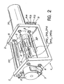
- FIG. 2 Reference will now be made to FIG. 2 to describe a particular hardware embodiment of the switch according to the invention.
- the assembly is carried out around a U-shaped profile body 1 taken from a standard aluminum profile.
- the motor M is mounted on one of the wings 2 of the profile and its axis passes through an orifice in this wing.
- This axis is integral with a rotating support 3 in aluminum which carries the magnet AP as well as a balancing flyweight 4 diametrically opposite.
- the potentiometer P is mounted coaxially on the other wing 5 of the profile 1.
- the coupling of the axes of the motor M and of the potentiometer P is carried out by an Oldham seal 6.
- the potentiometer P is held in position by clips 7 .
- the associated magnetic blade switches IM2, IM3, IM4, IM5 and IM5a associated both are mounted between the wings 2 and 5 of the profile and arranged parallel and equidistant from the geometric axis of the switch.
- the permanent magnet AP of slender shape, is mounted parallel to the axis of the switch so that it can be positioned near and parallel to one or the other of the flexible blade switches.
- These switches are. isolated from the profile by bushings 8 made of insulating material such as polytetrafluoroethylene, known under the trade name "Teflon".
- the high value resistors R2, R3 and R4 are wired between the insulating bushings 8 and an insulating plate 9, on the low potential side, and mounted on posts.
- the resistor R1, of larger dimension, is mounted with isolation between the two wings 2 and 5 of the profile.
- the assembly thus produced has overall dimensions of 70x45x30 mm. It is therefore a very compact switch.
- the invention is not limited to the examples described above. It can in particular be implemented for different numbers of measurement ranges and different measured current values.
Landscapes
- Physics & Mathematics (AREA)
- General Physics & Mathematics (AREA)
- Measurement Of Length, Angles, Or The Like Using Electric Or Magnetic Means (AREA)
- Adjustable Resistors (AREA)
- Rotary Switch, Piano Key Switch, And Lever Switch (AREA)
- Measuring Instrument Details And Bridges, And Automatic Balancing Devices (AREA)
Applications Claiming Priority (2)
| Application Number | Priority Date | Filing Date | Title |
|---|---|---|---|
| FR8212115A FR2530071B1 (fr) | 1982-07-09 | 1982-07-09 | Commutateur automatique a haut isolement et faibles consommation et encombrement |
| FR8212115 | 1982-07-09 |
Publications (3)
| Publication Number | Publication Date |
|---|---|
| EP0099290A2 true EP0099290A2 (de) | 1984-01-25 |
| EP0099290A3 EP0099290A3 (en) | 1984-02-22 |
| EP0099290B1 EP0099290B1 (de) | 1987-03-11 |
Family
ID=9275869
Family Applications (1)
| Application Number | Title | Priority Date | Filing Date |
|---|---|---|---|
| EP83401392A Expired EP0099290B1 (de) | 1982-07-09 | 1983-07-06 | Hochisolierter automatischer Schalter mit wenig Leistungs- und Raumbedarf |
Country Status (5)
| Country | Link |
|---|---|
| US (1) | US4555640A (de) |
| EP (1) | EP0099290B1 (de) |
| JP (1) | JPS5932871A (de) |
| DE (1) | DE3370188D1 (de) |
| FR (1) | FR2530071B1 (de) |
Cited By (5)
| Publication number | Priority date | Publication date | Assignee | Title |
|---|---|---|---|---|
| AU582176B2 (en) * | 1984-08-04 | 1989-03-16 | Robert Bosch Gmbh | Measuring means for provision of measurement valves in motor vehicle operation |
| FR2629290A1 (fr) * | 1988-01-28 | 1989-09-29 | Bicron Corp | Commutateur selecteur de gammes pour instrument a chambre d'ionisation |
| CN101034104B (zh) * | 2007-04-03 | 2010-04-21 | 方勇 | 四量程便携式电位差计 |
| CN101063691B (zh) * | 2007-05-29 | 2010-05-26 | 张春雷 | 三量程直流电位差计 |
| CN101034112B (zh) * | 2007-04-03 | 2010-05-26 | 程军 | 四量程电位差计 |
Families Citing this family (4)
| Publication number | Priority date | Publication date | Assignee | Title |
|---|---|---|---|---|
| US5258926A (en) * | 1988-08-08 | 1993-11-02 | Osterreichesches Forschungszentrum Seibersdorf Gmbh | Method of measuring radiation for a radiation measuring device |
| KR940001118B1 (ko) * | 1990-06-21 | 1994-02-14 | 미쯔비시 덴끼 가부시기가이샤 | 인출형 개폐기 |
| US20100225174A1 (en) * | 2009-03-05 | 2010-09-09 | Hao Jiang | Wireless Power Transfer Using Magnets |
| JP5379533B2 (ja) * | 2009-03-27 | 2013-12-25 | 大日本スクリーン製造株式会社 | 基板保持機構、およびこの基板保持機構を備える基板処理装置 |
Citations (5)
| Publication number | Priority date | Publication date | Assignee | Title |
|---|---|---|---|---|
| FR2001667A1 (de) * | 1968-02-09 | 1969-09-26 | Du Pont | |
| DE1563748A1 (de) * | 1966-09-08 | 1970-06-18 | Siemens Ag | Potentiometeranordnung |
| DE1923473A1 (de) * | 1969-05-08 | 1970-11-19 | Hartmann & Braun Ag | Messstellenumschalter fuer Mehrfach-Registriergeraete |
| FR2096102A5 (de) * | 1970-06-19 | 1972-02-11 | Guardigli Spa | |
| US3660789A (en) * | 1971-04-19 | 1972-05-02 | Thomas & Betts Corp | Rotary reed switch |
Family Cites Families (4)
| Publication number | Priority date | Publication date | Assignee | Title |
|---|---|---|---|---|
| DE1289901B (de) * | 1963-10-22 | 1969-02-27 | Siemens Ag | Magnetischer Drehschalter sehr grosser Lebensdauer |
| US3867687A (en) * | 1971-03-01 | 1975-02-18 | Honeywell Inc | Servo gain control of liquid conductivity meter |
| US4056733A (en) * | 1976-01-02 | 1977-11-01 | Combustion Engineering, Inc. | Panel board |
| JPS6026430Y2 (ja) * | 1980-11-19 | 1985-08-09 | 株式会社 千野製作所 | 切換器 |
-
1982
- 1982-07-09 FR FR8212115A patent/FR2530071B1/fr not_active Expired
-
1983
- 1983-07-06 DE DE8383401392T patent/DE3370188D1/de not_active Expired
- 1983-07-06 EP EP83401392A patent/EP0099290B1/de not_active Expired
- 1983-07-08 US US06/511,923 patent/US4555640A/en not_active Expired - Fee Related
- 1983-07-08 JP JP58124581A patent/JPS5932871A/ja active Pending
Patent Citations (5)
| Publication number | Priority date | Publication date | Assignee | Title |
|---|---|---|---|---|
| DE1563748A1 (de) * | 1966-09-08 | 1970-06-18 | Siemens Ag | Potentiometeranordnung |
| FR2001667A1 (de) * | 1968-02-09 | 1969-09-26 | Du Pont | |
| DE1923473A1 (de) * | 1969-05-08 | 1970-11-19 | Hartmann & Braun Ag | Messstellenumschalter fuer Mehrfach-Registriergeraete |
| FR2096102A5 (de) * | 1970-06-19 | 1972-02-11 | Guardigli Spa | |
| US3660789A (en) * | 1971-04-19 | 1972-05-02 | Thomas & Betts Corp | Rotary reed switch |
Non-Patent Citations (1)
| Title |
|---|
| ELECTRONIQUE ET APPLICATION INDUSTRIELLE, no. 255, juin 1978, page 16, Paris, FR; J. BRIAUD: "Changement de gamme automatique". * |
Cited By (5)
| Publication number | Priority date | Publication date | Assignee | Title |
|---|---|---|---|---|
| AU582176B2 (en) * | 1984-08-04 | 1989-03-16 | Robert Bosch Gmbh | Measuring means for provision of measurement valves in motor vehicle operation |
| FR2629290A1 (fr) * | 1988-01-28 | 1989-09-29 | Bicron Corp | Commutateur selecteur de gammes pour instrument a chambre d'ionisation |
| CN101034104B (zh) * | 2007-04-03 | 2010-04-21 | 方勇 | 四量程便携式电位差计 |
| CN101034112B (zh) * | 2007-04-03 | 2010-05-26 | 程军 | 四量程电位差计 |
| CN101063691B (zh) * | 2007-05-29 | 2010-05-26 | 张春雷 | 三量程直流电位差计 |
Also Published As
| Publication number | Publication date |
|---|---|
| FR2530071B1 (fr) | 1985-10-25 |
| EP0099290A3 (en) | 1984-02-22 |
| US4555640A (en) | 1985-11-26 |
| EP0099290B1 (de) | 1987-03-11 |
| FR2530071A1 (fr) | 1984-01-13 |
| DE3370188D1 (en) | 1987-04-16 |
| JPS5932871A (ja) | 1984-02-22 |
Similar Documents
| Publication | Publication Date | Title |
|---|---|---|
| EP0099290B1 (de) | Hochisolierter automatischer Schalter mit wenig Leistungs- und Raumbedarf | |
| WO2019097152A1 (fr) | Dispositif de coupure pyrotechnique | |
| EP0007867A1 (de) | Verbesserungen an Vorrichtungen zum Feststellen des Bruchs eines Elements einer elektrischen Schaltung | |
| FR3038781A1 (fr) | Ensemble de prise electrique avec solution de deconnexion electrique | |
| EP0057338A2 (de) | Steuergerät für den Antriebsmotor einer Schiebewand eines Kraftfahrzeuges, insbesondere für eine Fensterhebeanlage | |
| FR2492157A1 (fr) | Dispositif combine de demarrage et de protection de moteur electrique monophase utilisant une thermistance de demarrage | |
| EP1557922A1 (de) | Differentialschutzvorrichtung mit vereinfachten Einstellmitteln für die Schutzparameter | |
| EP0204624A1 (de) | Einrichtung zur Überwachung des Zustands eines elektrischen Schalters und Anwendung in einem elektrischen Relais | |
| WO2011069879A1 (fr) | Dispositif generateur d'energie electrique | |
| FR2867322A1 (fr) | Appareil electromenager incluant un moteur electrique | |
| EP2085987A1 (de) | Steuerungsvorrichtung mit zwei verschiedenen Betätigungsarten | |
| FR2649260A1 (fr) | Dispositif d'arret d'un moteur asynchrone monophase a condensateur | |
| EP2328132B1 (de) | Fernsteuerungsvorrichtung | |
| EP0235623B1 (de) | Vorrichtung zur Einstellung der Polarisation einer Antenne und Verfahren zur Durchführung der Einstellung mit einer solchen Vorrichtung | |
| EP3699942B1 (de) | Einschaltsystem einer vakuumschaltröhre | |
| EP2192605B1 (de) | Trennvorrichtung eines elektrischen Schaltkreises und Stromverteilungskasten, der mit einer solchen Trennvorrichtung ausgestattet ist | |
| FR2739971A1 (fr) | Mecanisme d'entrainement de contacts de signalisation d'un appareil electrique en particulier d'un sectionneur ou sectionneur de terre haute tension | |
| CH716204B1 (fr) | Combiné disjoncteur et interrupteur sectionneur. | |
| FR2738952A1 (fr) | Disjoncteur de protection contre les fuites a la masse | |
| CH634687A5 (en) | Rotating-arc and self-blasting high-voltage circuit breaker | |
| FR2694444A1 (fr) | Perfectionnements aux dispositifs de coupure de ligne électrique. | |
| FR2498807A1 (fr) | Relais monostable a faible consommation | |
| FR2694986A1 (fr) | Perfectionnements aux dispositifs de coupure de ligne électrique. | |
| FR2698958A1 (fr) | Dispositif de sécurité pour une munition. | |
| FR2534080A1 (fr) | Appareil de mise a la masse automatique de structures accidentellement sous tension |
Legal Events
| Date | Code | Title | Description |
|---|---|---|---|
| PUAI | Public reference made under article 153(3) epc to a published international application that has entered the european phase |
Free format text: ORIGINAL CODE: 0009012 |
|
| PUAL | Search report despatched |
Free format text: ORIGINAL CODE: 0009013 |
|
| AK | Designated contracting states |
Designated state(s): CH DE GB IT LI |
|
| AK | Designated contracting states |
Designated state(s): CH DE GB IT LI |
|
| 17P | Request for examination filed |
Effective date: 19840723 |
|
| GRAA | (expected) grant |
Free format text: ORIGINAL CODE: 0009210 |
|
| AK | Designated contracting states |
Kind code of ref document: B1 Designated state(s): CH DE GB IT LI |
|
| REF | Corresponds to: |
Ref document number: 3370188 Country of ref document: DE Date of ref document: 19870416 |
|
| ITF | It: translation for a ep patent filed |
Owner name: JACOBACCI & PERANI S.P.A. |
|
| PLBE | No opposition filed within time limit |
Free format text: ORIGINAL CODE: 0009261 |
|
| STAA | Information on the status of an ep patent application or granted ep patent |
Free format text: STATUS: NO OPPOSITION FILED WITHIN TIME LIMIT |
|
| RAP2 | Party data changed (patent owner data changed or rights of a patent transferred) |
Owner name: COMMISSARIAT A L'ENERGIE ATOMIQUE |
|
| 26N | No opposition filed | ||
| PGFP | Annual fee paid to national office [announced via postgrant information from national office to epo] |
Ref country code: CH Payment date: 19890614 Year of fee payment: 7 |
|
| PGFP | Annual fee paid to national office [announced via postgrant information from national office to epo] |
Ref country code: DE Payment date: 19890705 Year of fee payment: 7 |
|
| ITTA | It: last paid annual fee | ||
| PGFP | Annual fee paid to national office [announced via postgrant information from national office to epo] |
Ref country code: GB Payment date: 19890731 Year of fee payment: 7 |
|
| PG25 | Lapsed in a contracting state [announced via postgrant information from national office to epo] |
Ref country code: GB Effective date: 19900706 |
|
| PG25 | Lapsed in a contracting state [announced via postgrant information from national office to epo] |
Ref country code: LI Effective date: 19900731 Ref country code: CH Effective date: 19900731 |
|
| GBPC | Gb: european patent ceased through non-payment of renewal fee | ||
| REG | Reference to a national code |
Ref country code: CH Ref legal event code: PL |
|
| PG25 | Lapsed in a contracting state [announced via postgrant information from national office to epo] |
Ref country code: DE Effective date: 19910403 |