EP0099290A2 - Highly insulated automatic switch using little consumption and space - Google Patents
Highly insulated automatic switch using little consumption and space Download PDFInfo
- Publication number
- EP0099290A2 EP0099290A2 EP83401392A EP83401392A EP0099290A2 EP 0099290 A2 EP0099290 A2 EP 0099290A2 EP 83401392 A EP83401392 A EP 83401392A EP 83401392 A EP83401392 A EP 83401392A EP 0099290 A2 EP0099290 A2 EP 0099290A2
- Authority
- EP
- European Patent Office
- Prior art keywords
- switch
- motor
- permanent magnet
- amplifier
- flexible blade
- Prior art date
- Legal status (The legal status is an assumption and is not a legal conclusion. Google has not performed a legal analysis and makes no representation as to the accuracy of the status listed.)
- Granted
Links
Images

Classifications
-
- G—PHYSICS
- G01—MEASURING; TESTING
- G01R—MEASURING ELECTRIC VARIABLES; MEASURING MAGNETIC VARIABLES
- G01R15/00—Details of measuring arrangements of the types provided for in groups G01R17/00 - G01R29/00, G01R33/00 - G01R33/26 or G01R35/00
- G01R15/08—Circuits for altering the measuring range
- G01R15/09—Autoranging circuits
-
- H—ELECTRICITY
- H01—ELECTRIC ELEMENTS
- H01H—ELECTRIC SWITCHES; RELAYS; SELECTORS; EMERGENCY PROTECTIVE DEVICES
- H01H36/00—Switches actuated by change of magnetic field or of electric field, e.g. by change of relative position of magnet and switch, by shielding
- H01H36/0006—Permanent magnet actuating reed switches
- H01H36/006—Permanent magnet actuating reed switches comprising a plurality of reed switches, e.g. selectors or joystick-operated
Landscapes
- Physics & Mathematics (AREA)
- General Physics & Mathematics (AREA)
- Measurement Of Length, Angles, Or The Like Using Electric Or Magnetic Means (AREA)
- Adjustable Resistors (AREA)
- Measuring Instrument Details And Bridges, And Automatic Balancing Devices (AREA)
- Rotary Switch, Piano Key Switch, And Lever Switch (AREA)
Abstract
Commutateur automatique à haut isolement et faibles consommation et encombrement. Ce commutateur est destiné à être associé à un appareil de mesure de courants très faibles (10<-><7> à 10<->¹<4> ampère) comprenant un amplificateur contrôlé par un transistor d'entrée à effet de champ (TR1). L'invention vise à commuter sur cet amplificateur des résistances de hautes valeurs (R1, R2, R3, R4) à l'aide d'interrupteurs à lame souple à commande magnétique (IM2, IM3, IM4) actionnées par un aimant permanent (AP) commandé lui-même par un asservissement classique à moteur (M) et potentiomètre (P) piloté par microprocesseur (MP). D'autres interrupteurs (IM5, IM5a) assurant la protection du transistor (TR1). L'invention sert notamment à la mesure des courants délivrés par des chambres d'ionisation.Automatic switch with high insulation and low consumption and size. This switch is intended to be associated with a device for measuring very low currents (10 <-> <7> to 10 <-> ¹ <4> ampere) comprising an amplifier controlled by a field effect input transistor ( TR1). The invention aims to switch high-value resistors (R1, R2, R3, R4) to this amplifier using flexible blade switches with magnetic control (IM2, IM3, IM4) actuated by a permanent magnet (AP ) itself controlled by a conventional servo motor (M) and potentiometer (P) controlled by microprocessor (MP). Other switches (IM5, IM5a) ensuring the protection of the transistor (TR1). The invention is used in particular for measuring the currents delivered by ionization chambers.
Description
La présente invention concerne un commutateur automatique à haut isolement et faibles consommation et encombrement. Elle concerne le domaine de la mesure électrique de courants d'intensités très faibles dont les valeurs s'échelonnent sur plusieurs décades et, plus particulièrement, concerne le cas où cette mesure est effectuée, de manière connue, à l'aide d'un appareil électrométrique constitué d'un amplificateur intégré précédé' d'au moins un transistor à effet de champ à porte isolée de très faible courant de fuite, l'ensemble transistor-amplificateur étant contre-réactionné linéairement par des résistances de hautes valeurs que l'on commute selon la gamme de mesures à mettre en oeuvre.The present invention relates to an automatic switch with high insulation and low consumption and size. It relates to the field of electric measurement of currents of very low intensities whose values are spread over several decades and, more particularly, relates to the case where this measurement is carried out, in known manner, using a device electrometric consisting of an integrated amplifier preceded by at least one field effect transistor with insulated gate of very low leakage current, the transistor-amplifier assembly being counter-reacted linearly by resistors of high values which are switches according to the range of measures to be implemented.
Par exemple, ce cas est celui de la mesure des courants très faibles, d'intensités comprises entre 10-14 et 10-7 ampère, issus d'une chambre d'ionisation. Les valeurs des résistances de contre-réaction sont alors comprises entre 10 et 10 12 ohms selon la gamme de mesure.For example, this case is that of measuring very low currents, with intensities between 10 -14 and 10 -7 amps, coming from an ionization chamber. The values of the feedback resistances are then between 10 and 10 12 ohms depending on the measurement range.
L'invention est plus précisément relative au dispositif de commutation utilisé pour commuter ces résistances de hautes valeurs, et qui doit posséder des caractéristiques d'isolement compatibles avec ces valeurs élevées de résistances.The invention relates more precisely to the switching device used to switch these high-value resistances, and which must have insulation characteristics compatible with these high resistance values.
Plus précisément encore, l'invention est relative aux dispositifs antérieurement connus de commutation qui utilisent des interrupteurs à lame souple à commande magnétique enfermés dans des ampoules, connus sous les références commerciales d'ampoules Reed ou d'interrupteurs ILS, montés en série avec les différentes résistances de hautes valeurs utilisées pour les différentes gammes de mesure, et qui se ferment lorsqu'ils sont soumis à l'action d'un champ magnétique.More specifically still, the invention relates to previously known switching devices which use flexible blade switches with magnetic control enclosed in bulbs, known under the commercial references of Reed bulbs or ILS switches, mounted in series with the different high value resistors used for the different ranges of measure, and which close when subjected to the action of a magnetic field.
Jusqu'alors, dans les dispositifs de commutation connus d'un premier type, ce champ magnétique est engendré par des relais qui présentent l'inconvénient d'avoir une consommation assez élevée à cause de leur circuit magnétique qui doit être imparfaitement fermé afin de respecter les lignes de fuite de l'ampoule-interrupt-eur nécessaires à l'isolement.Until then, in known switching devices of a first type, this magnetic field is generated by relays which have the disadvantage of having a fairly high consumption because of their magnetic circuit which must be imperfectly closed in order to respect the leakage lines of the interrupter bulb required for isolation.
Dans les dispositifs de commutation connus d'un second type, ce champ magnétique est engendré par un aimant permanent qu'un dispositif de commande manuelle vient positionner devant celle des ampoules-interrupteurs dont on désire fermer le contact. On évite ainsi l'inconvénient précité d'une consommation permanente de courant élevée, mais au prix de l'inconvénient d'utiliser une commande manuelle.In known switching devices of a second type, this magnetic field is generated by a permanent magnet which a manual control device comes to position in front of that of the switch bulbs whose contact is to be closed. This avoids the aforementioned drawback of a high permanent current consumption, but at the cost of the drawback of using a manual control.
L'invention a pour but de supprimer ces deux inconvénients, ce qui est particulièrement nécessaire lorsque l'on désire disposer d'un appareil de mesure de courants très faibles portatif et automatique. Dans ce cas-là, il faut alors nécessairement et conjointement que l'appareil soit alimenté par piles donc à consommation minimale, que les gammes de mesures soient commutées automatiquement, et que l'ensemble soit d'un poids et d'un encombrement restreints.The object of the invention is to eliminate these two drawbacks, which is particularly necessary when it is desired to have a portable and automatic device for measuring very low currents. In this case, it is then necessary necessarily and jointly that the device is powered by batteries therefore at minimum consumption, that the ranges of measurements are switched automatically, and that the whole is of a weight and a restricted size. .
A ces effets, l'invention a donc pour objet un commutateur automatique à haut isolement et faibles consommation et encombrement, destiné à être associé à un appareil électrométrique constitué d'un amplificateur intégré précédé d'au moins un transistor à effet de champ à porte isolée de très faible courant de fuite, l'ensemble transistor-amplificateur étant contre-réactionné linéairement par des résistances de hautes valeurs commutées selon la gamme de mesures à mettre en oeuvre par des interrupteurs à lame souple à commande magnétique engendrée par un aimant permanent, caractérisé en ce qu'il comporte en outre un servo-mécanisme, du type connu en soi, à moteur et potentiomètre pour positionner ledit aimant permanent en regard de l'un desdits interrupteurs à lame souple à commande magnétique, des moyens étant prévus pour comparer la tension de sortie dudit amplificateur à la tension délivrée par ledit potentiomètre et caractéristique de la position dudit aimant permanent et commander en conséquence ledit moteur de déplacement de l'aimant.To these effects, the invention therefore relates to an automatic switch with high isolation and low consumption and size, intended to be associated with an electrometric device consisting of an integrated amplifier preceded by at least one field effect transistor with gate isolated from very low leakage current, the transistor-amplifier assembly being linearly counter-reacted by resistors of high values switched according to the range of measurements to be implemented by flexible blade switches with magnetic control generated by a permanent magnet, characterized in which it further comprises a servo-mechanism, of the type known per se, with motor and potentiometer for positioning said permanent magnet opposite one of said flexible blade switches with magnetic control, means being provided for comparing the voltage output of said amplifier at the voltage delivered by said potentiometer and characteristic of the position of said permanent magnet and control said magnet displacement motor accordingly.
L'automaticité du commutateur selon l'invent.ion est assurée par l'utilisation en combinaison avec lui du servo-mécanisme et de ses moyens de commande, qui peuvent être réalisés très simplement à l'aide de moyens connus, tels que dispositif convertisseur analogique-digital, et dispositif microprocesseur, comme on le décrira ci-après plus en détail.The automaticity of the switch according to the invent.ion is ensured by the use in combination with it of the servo-mechanism and of its control means, which can be produced very simply using known means, such as converter device. analog-digital, and microprocessor device, as will be described below in more detail.
Le haut isolement du commutateur résulte de l'emploi, en série avec les résistances de hautes valeurs correspondant aux différentes gammes de mesure, d'interrupteurs à lame souple à commande magnétique à très haut isolement, par exemple supérieur à 10 ohms.The high insulation of the switch results from the use, in series with the high value resistances corresponding to the different measurement ranges, of flexible blade switches with magnetic control with very high insulation, for example greater than 10 ohms.
La faible consommation du commutateur résulte de ce que le moteur du servo-mécanisme ne consomme de courant qu'au moment d'une commutation, son courant de repos en position stable étant nul.The low consumption of the switch results from the fact that the servo-motor consumes current only at the time of a switching, its quiescent current in stable position being zero.
La combinaison de moyens de l'invention permet un positionnement très précis de l'aimant permanent en chacune de ses positions stables, ce qui permet une optimalisation des dimensions des divers éléments composants du commutateur et, par conséquent, la réduction optimale de son encombrement, nécessaire à la réalisation d'un appareil portatif.The combination of means of the invention allows very precise positioning of the magnet permanent in each of its stable positions, which allows an optimization of the dimensions of the various components of the switch and, therefore, the optimal reduction of its size, necessary for the realization of a portable device.
L'invention a pour autre but de protéger avec toute garantie le transistor à effet de champ à l'entrée de l'amplificateur lorsque l'appareil est hors tension. En effet, la porte isolée de ce transistor est extrêmement sensible aux surcharges électriques ou électrostatiques dues aux variations transitoires de tension se produisant à la mise sous tension de l'appareil de mesure, tant que le régime n'est pas complètement établi.Another object of the invention is to protect with any guarantee the field effect transistor at the input of the amplifier when the device is switched off. Indeed, the insulated gate of this transistor is extremely sensitive to electrical or electrostatic overloads due to transient voltage variations occurring when the measuring device is energized, as long as the regime is not completely established.
A cet effet, l'invention a pour autre objet un commutateur du type précité, caractérisé en ce qu'un autre interrupteur à lame souple à commande magnétique en regard duquel vient se placer ledit aimant permanent après arrêt de l'appareil assure la mise en court-circuit dudit ensemble transistor-amplificateur lorsque l'appareil est hors tension.To this end, the invention has for another object a switch of the aforementioned type, characterized in that another flexible blade switch with magnetic control opposite which is placed said permanent magnet after stopping the device ensures the setting short circuit of said transistor-amplifier assembly when the device is switched off.
Selon un mode de réalisation particulier de l'invention, ledit autre interrupteur à lame souple à commande magnétique est associé à un autre interrupteur à lame souple à commande magnétique de coupure d'alimentation de l'appareil de mesure en position arrêt.According to a particular embodiment of the invention, said other switch with flexible blade with magnetic control is associated with another switch with flexible blade with magnetic control for cutting off the supply of the measuring device in the off position.
La présente invention a encore pour autre but de réaliser matériellement un sous-composant de l'appareil de mesure proprement dit comprenant : les ampoules-interrupteurs, leurs résistances de hautes valeurs montées en série avec elles, le moteur et le potentiomètre du servo-mécanisme, qui soit simple, compact et miniaturisé.Another object of the present invention is to provide a physical component of the actual measuring device comprising: the switch bulbs, their high value resistors connected in series with them, the motor and the potentiometer of the servo-mechanism. , which is simple, compact and miniaturized.
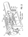
A ces effets, l'invention a pour autre objet un commutateur du type précité, caractérisé en ce qu'il comporte : un corps profilé en U ayant une base et deux ailes parallèles en regard ; un moteur de servo-mécanisme monté à l'extérieur du corps sur l'une des ailes, son axe passant par un orifice de cette aile ; un potentiomètre de servo-mécanisme monté à 1'.extérieur du corps sur l'autre aile, son axe. étant coaxial avec le premier axe et passant par un orifice de cette autre aile ; un accouplement élastique connectant mécaniquement les deux axes précités du moteur et du potentiomètre ; un aimant permanent de forme rectiligne, parallèle aux axes précités, excentré par rapport à eux et entraîné en rotation par l'axe du moteur ; plusieurs ampoules-interrupteurs à lame souple à commande magnétique montées entre les deux ailes du corps profilé parallèlement à l'axe du moteur à même distance de cet axe et régulièrement espacées les unes des autres de telle sorte que ledit aimant permanent lors de sa rotation vient se placer successivement en regard et à proximité de ces ampoules-interrupteurs pour les commander ; et plusieurs résistances de hautes valeurs montées sur l'une et/ou l'autre des ailes du corps profilé.For these purposes, the invention has as another object a switch of the aforementioned type, characterized in that it comprises: a U-shaped body having a base and two opposite wings opposite; a servo-mechanism motor mounted outside the body on one of the wings, its axis passing through an orifice in this wing; a servo-mechanism potentiometer mounted outside the body on the other wing, its axis. being coaxial with the first axis and passing through an orifice of this other wing; an elastic coupling mechanically connecting the two aforementioned axes of the motor and the potentiometer; a permanent magnet of rectilinear shape, parallel to the aforementioned axes, eccentric with respect to them and driven in rotation by the axis of the motor; several switch blades with a flexible blade with magnetic control mounted between the two wings of the profiled body parallel to the axis of the motor at the same distance from this axis and regularly spaced from each other so that said permanent magnet when it rotates comes place yourself successively next to and near these switch bulbs to control them; and several high value resistors mounted on one and / or the other of the wings of the profiled body.
Un avantage supplémentaire de l'invention résulte de ce mode de réalisation et consiste en ce que l'on peut ainsi obtenir une excellente stabilité de chaque position de l'aimant permanent en l'une ou l'autre de ses différentes positions possibles. Cette stabilité n'est pas affectée par des chocs et/ou vibrations.An additional advantage of the invention results from this embodiment and consists in that one can thus obtain excellent stability of each position of the permanent magnet in one or other of its different possible positions. This stability is not affected by shocks and / or vibrations.
Pour mieux faire comprendre tous les buts, objets et avantages exposés ci-dessus de l'invention, on en décrira maintenant un exemple non limitatif de réalisation.To better understand all the aims, objects and advantages set out above of the invention, a non-limiting example of embodiment will now be described.
On le fera en se reportant au dessin annexé, sur lequel :
- - la figure 1 est le schéma électrique et électronique du commutateur et de ses moyens fonctionnels de commande, et
- - la figure 2 est une vue en perspective d'une réalisation matérielle avantageuse du commutateur de la figure 1.
- FIG. 1 is the electrical and electronic diagram of the switch and of its functional control means, and
- - Figure 2 is a perspective view of an advantageous hardware embodiment of the switch of Figure 1.
Le courant très faible à mesurer, d'intensité I, provenant par exemple d'une chambre d'ionisation, est appliqué à la porte d'un transistor MOS Fet à effet de champ TR1 précédant un amplificateur intégré AI.The very weak current to be measured, of intensity I, coming for example from an ionization chamber, is applied to the gate of a MOS Fet transistor with field effect TR1 preceding an integrated amplifier AI.
Par exemple, I variera sur 7 décades avec des intensités de 10-14 à 10-7 ampère.For example, I will vary over 7 decades with intensities from 10 -14 to 10 -7 amps.
Cet ensemble transistor TRi-amplificateur AI est contre-réactionné linéairement par des résistances de hautes valeurs R4, R3, R2, Rl de valeurs respectives 10 6, 108, 1010 et 1012 ohms suivant la gamme de mesure.This transistor TRi-amplifier AI assembly is linearly counter-reacted by resistors of high values R4, R3, R2, Rl of respective values 10 6 , 10 8 , 10 10 and 10 12 ohms according to the measurement range.
Les résistances R2, R3 et R4 sont montées en série avec des éléments de commutation constitués d'interrupteurs à lame souple à commande magnétique IM2, IM3 et IM4, tels que des ampoules Reed.The resistors R2, R3 and R4 are connected in series with switching elements made up of soft-blade switches with magnetic control IM2, IM3 and IM4, such as Reed bulbs.
Ces interrupteurs sont fermés par un aimant permanent tournant AP qui est entraîné en rotation par un moteur M d'un servo-mécanisme, actionnant également le déplacement du curseur d'un potentiomètre P.These switches are closed by a permanent rotating magnet AP which is rotated by a motor M of a servo-mechanism, also actuating the movement of the cursor of a potentiometer P.
On a schématisé par un cercle en traits interrompus le mouvement circulaire de l'aimant AP et repéré en pl, p2, p3, p4 et p5 les cinq positions stables qu'il est susceptible d'occuper.The circular movement of the magnet AP has been shown diagrammatically by a dashed line and identified in p1, p2, p3, p4 and p5 the five stable positions which it is likely to occupy.
En position pl, la résistance Rl est en contre-réaction de l'amplificateur AI. En position p2, les résistances R1 et R2 en parallèle sont en service. En position p3, les résistances Rl et R3 en parallèle sont en service. En position p4, les résistances Rl et R4 en parallèle sont en service.In position pl, the resistance R1 is in feedback from the amplifier AI. In position p2, the resistors R1 and R2 in parallel are in service. In position p3, the resistors R1 and R3 in parallel are in service. In position p4, the resistors R1 and R4 in parallel are in service.
En position p5, qui correspond à la position de l'aimant AP représentée sur la figure 1, un interrupteur IM5 se ferme, mettant en court-circuit l'ensemble transistor TRi-amplificateur AI. Cet interrupteur est doublé d'un autre interrupteur IM5a, qui s'ouvre sous l'action de l'aimant AP et coupe l'alimentation générale de l'appareil électrométrique comme on l'expliquera ci-après.In position p5, which corresponds to the position of the magnet AP shown in FIG. 1, a switch IM5 closes, shorting the transistor TRi-amplifier AI assembly. This switch is coupled with another switch IM5a, which opens under the action of the magnet AP and cuts the general supply of the electrometric device as will be explained below.
L'ensemble des éléments comprenant le moteur M, le potentiomètre P, l'aimant permanent AP, les résistances de hautes valeurs Rl, R2, R3 et R4 et les interrupteurs à commande magnétique IM2, IM3, IM4, IM5 et IM5a, et représenté à l'intérieur du cadre en traits mixtes C, constitue la combinaison de moyens caractéristique du commutateur selon l'invention.All the elements including the motor M, the potentiometer P, the permanent magnet AP, the high value resistors Rl, R2, R3 and R4 and the magnetically controlled switches IM2, IM3, IM4, IM5 and IM5a, and shown inside the frame in phantom C, constitutes the combination of means characteristic of the switch according to the invention.
Cette combinaison de moyens est pilotée par un microprocesseur MP dont la fonction essentielle consiste à prendre en compte la tension de sortie Us de l'amplificateur AI et la tension Up prélevée sur le curseur du potentiomètre P, à les comparer à des valeurs de référence stockées en mémoire, et à contrôler en conséquence le moteur M de commande du commutateur. Le microprocesseur MP contrôle également l'affichage de la gamme de mesure utilisée et de la mesure faite dans un dispositif d'affichage AF de tout type connu.This combination of means is controlled by a microprocessor MP whose essential function consists in taking into account the output voltage Us of the amplifier AI and the voltage Up taken from the cursor of the potentiometer P, to compare them with stored reference values. in memory, and to control the switch control motor M accordingly. The microprocessor MP also controls the display of the measurement range used and of the measurement made in an AF display device of any known type.
Afin de limiter le nombre des résistances de hautes valeurs à commuter, on utilise une commutation de gain de l'amplificateur AI de 1 et de 10, commutation à basse impédance réalisée par un commutateur en semi-conducteur- intégré de type connu schématisé en CG.In order to limit the number of high-value resistors to be switched, an AI amplifier gain switch of 1 and 10 is used, low impedance switching carried out by a com semiconductor-integrated mutator of known type shown diagrammatically in CG.
Les tensions Us et Up sont successivement testées, à l'aide d'un interrupteur analogique IA de type connu, et digitalisées par un convertisseur A/D analogue/digital, également de type connu.The voltages Us and Up are successively tested, using an analog switch IA of known type, and digitized by an analog / digital A / D converter, also of known type.
Le fonctionnement de l'ensemble commutateur-appareil électrométrique décrit ci-dessus est le suivant.The operation of the switch-electrometric device assembly described above is as follows.
Lorsque l'appareil est en position "arrêt", le commutateur C est en position p5, c'est-à-dire que l'amplificateur AI est en court-circuit et que l'alimentation électrique est coupée par l'interrupteur IM5a alors ouvert par l'aimant AP qui est en regard de lui. On expliquera ci-après comment l'on obtient cette situation initiale.When the device is in the "off" position, the switch C is in the p5 position, that is to say that the amplifier AI is in short circuit and that the electrical supply is cut by the switch IM5a then opened by the AP magnet which is next to it. We will explain below how this initial situation is obtained.
Lorsque l'appareil est mis en position "marche" par le commutateur Marche-Arrêt manuel, le microprocesseur MP donne l'ordre au moteur M de tourner. L'interrupteur IM5a se ferme, se mettant alors en parallèle avec le commutateur Marche-Arrêt manuel.When the device is placed in the "on" position by the manual on-off switch, the microprocessor MP gives the order to the motor M to run. The IM5a switch closes, putting itself in parallel with the manual on-off switch.
L'aimant AP se met en marche vers la position p4 pour mesurer éventuellement le courant 1 le plus fort (10-7 ampère) avec la résistance la plus faible (R4, valeur 10 ohms, en parallèle avec Rl, valeur 10 12 ohms).The magnet AP starts to position p4 to possibly measure the strongest current 1 (10 -7 amps) with the lowest resistance (R4, value 10 ohms, in parallel with Rl, value 10 12 ohms) .
Le microprocesseur MP compare la tension Up sur le curseur du potentiomètre P à la valeur de consigne contenue en mémoire et correspondant à la position p4. Lorsque ces valeurs sont égales, le moteur M est arrêté en position p4 et le microprocesseur MP se commute, par l'action de l'interrupteur analogique IA, sur la tension de sortie Us de l'amplificateur AI.The microprocessor MP compares the voltage Up on the cursor of the potentiometer P with the reference value contained in memory and corresponding to the position p4. When these values are equal, the motor M is stopped in position p4 and the microprocessor MP is switched, by the action of the analog switch IA, to the output voltage Us of the amplifier AI.
Cette tension de sortie Us est d'abord testée en gain de 10.This output voltage Us is first tested in gain of 10.
Si la valeur de la tension Us est comprise entre 10% et 100% de la première gamme de mesures à laquelle correspond l'amplificateur AI contre-réactionné par les résistances R4 et RI en parallèle et avec un gain de 10, le commutateur reste en cette première position p4 de mesure.If the value of the voltage Us is between 10% and 100% of the first range of measurements to which the amplifier AI responds by the resistors R4 and RI in parallel and with a gain of 10, the switch remains in this first measurement position p4.
Si la valeur de la tension Us est inférieure à 10% de cette gamme de mesures précitée, le commutateur de gain CG passe du gain 10 au gain 1, et le microprocesseur MP donne l'ordre au moteur M de déplacer l'aimant permanent AP de la position p4 vers la position p3.If the value of the voltage Us is less than 10% of this aforementioned range of measurements, the gain switch CG goes from gain 10 to gain 1, and the microprocessor MP gives the order to the motor M to move the permanent magnet AP from position p4 to position p3.
Si la valeur de la tension Us est alors comprise entre 10% et 100% de la seconde gamme de mesures à laquelle correspond l'amplificateur AI contre-réactionné par les résistances R3 et Rl en parallèle et avec un gain de 1, le commutateur reste en cette nouvelle position p3 de me.sure.If the value of the voltage Us is then between 10% and 100% of the second range of measurements to which corresponds the amplifier AI counter-reacted by the resistors R3 and Rl in parallel and with a gain of 1, the switch remains in this new position p3 of measurement.
Si la valeur de la tension Us est inférieure à 10% de cette seconde gamme de mesures, le microprocesseur MP donne l'ordre au commutateur de gain CG de passer du gain de 1 au gain de 10.If the value of the voltage Us is less than 10% of this second range of measurements, the microprocessor MP gives the order to the gain switch CG to pass from the gain of 1 to the gain of 10.
Il se déroule ensuite le même cycle de fonctionnement que celui décrit précédemment pour passer de la position p3 à la position p2, puis pl.The same operating cycle then takes place as that described above in order to pass from position p3 to position p2, then pl.
Ainsi, le microprocesseur surveille en permanence la tension Us ; si celle-ci vient à croître et dépasser le haut de gamme de mesures, le microprocesseur donne l'ordre de commuter sur la gamme supérieure de mesures (à la fois en commutant le gain de 1 à 10 et en commutant d'une résistance à la résistance de valeur immédiatement inférieure) ; si elle décroît en-dessous de 10% de la gamme de mesures, le microprocesseur donne l'ordre de commuter sur la gamme inférieure de mesure (à la fois en commutant le gain de 10 à 1 et en commutant d'une résistance à la résistance de valeur immédiatement supérieure).Thus, the microprocessor continuously monitors the voltage Us; if this increases and exceeds the high range of measurements, the microprocessor gives the order to switch to the upper range of measurements (both by switching the gain from 1 to 10 and by switching from a resistance to resistance immediately below value); if it decreases below 10% of the measurement range, the microprocessor gives the order to switch to the lower measurement range (both by switching the gain from 10 to 1 and by switching resistance to resistance of immediately higher value).
Lorsque l'on cesse d'utiliser l'appareil de mesure et que l'opérateur le met donc en position "arrêt", le microprocesseur envoie au moteur M l'instruction de tourner jusqu'à la position p5. L'appareil reste alimenté par l'interrupteur IM5a qui reste fermé tant que l'aimant AB n'est pas parvenu en cette position p5. Lorsqu'il y parvient, on obtient la coupure de l'alimentation et la mise en court-circuit de l'ensemble transistor TRl-amplificateur AI par fermeture de l'interrupteur IM5. Cela met en position de sécurité le commutateur C pour protéger le transistor TRI lors de la prochaine mise sous tension de l'appareil.When the measurement device is no longer used and the operator therefore puts it in the "off" position, the microprocessor sends the motor M the instruction to turn to the position p5. The device remains powered by the switch IM5a which remains closed as long as the magnet AB has not reached this position p5. When this is achieved, the power supply is cut off and the transistor TRl-amplifier AI assembly is short-circuited by closing the switch IM5. This puts switch C in the safety position to protect the TRI transistor when the device is next powered up.
On se reportera maintenant à la figure 2 pour décrire un mode particulier de réalisation matérielle du commutateur selon l'invention.Reference will now be made to FIG. 2 to describe a particular hardware embodiment of the switch according to the invention.
La réalisation mécanique et le choix des composants ont été faits dans le but d'obtenir un ensemble simple et compact.The mechanical production and the choice of components were made with the aim of obtaining a simple and compact assembly.
Le montage est réalisé autour d'un corps profilé 1 en U pris dans un profilé standard en aluminium.The assembly is carried out around a U-shaped profile body 1 taken from a standard aluminum profile.
Le moteur M est monté sur l'une des ailes 2 du profilé et son axe passe à travers un orifice de cette aile. Cet axe est solidaire d'un support tournant 3 en aluminium qui porte l'aimant AP ainsi qu'une masselotte d'équilibrage 4 diamétralement opposée.The motor M is mounted on one of the wings 2 of the profile and its axis passes through an orifice in this wing. This axis is integral with a rotating support 3 in aluminum which carries the magnet AP as well as a balancing flyweight 4 diametrically opposite.
Le potentiomètre P est monté coaxiale- ment sur l'autre aile 5 du profilé 1. L'accouplement des axes du moteur M et du potentiomètre P est réalisé par un joint de Oldham 6. Le potentiomètre P est maintenu en position par des clips 7.The potentiometer P is mounted coaxially on the
Les interrupteurs à lame souple à commande magnétique IM2, IM3, IM4, IM5 et IM5a associés tous deux, sont montés entre les ailes 2 et 5 du profilé et disposés parallèlement et équidistants de l'axe géométrique du commutateur. L'aimant permanent AP, de forme longiligne, est monté parallèlement à l'axe du commutateur de manière à pouvoir venir se positionner à proximité de et parallèlement à l'un ou l'autre des interrupteurs à lame souple. Ces interrupteurs sont. isolés du profilé par des traversées 8 en matériau isolant tel que du polytétrafluoroéthylène, connu sous la dénomination commerciale de "téflon".The associated magnetic blade switches IM2, IM3, IM4, IM5 and IM5a associated both are mounted between the
Les résistances de hautes valeurs R2, R3 et R4 sont câblées entre les traversées isolantes 8 et une plaquette isolante 9, côté bas potentiel, et montées sur colonnettes. La résistance Rl, de plus grande dimension, est montée avec isolement entre les deux ailes 2 et 5 du profilé.The high value resistors R2, R3 and R4 are wired between the insulating
L'ensemble ainsi réalisé a des dimensions hors tout de 70x45x30 mm. Il s'agit donc d'un commutateur très compact.The assembly thus produced has overall dimensions of 70x45x30 mm. It is therefore a very compact switch.
L'invention n'est pas limitée aux exemples décrits ci-dessus. Elle peut notamment être mise en oeuvre pour des nombres différents de gammes de mesures et des valeurs différentes de courant mesurées.The invention is not limited to the examples described above. It can in particular be implemented for different numbers of measurement ranges and different measured current values.
Claims (4)
Applications Claiming Priority (2)
| Application Number | Priority Date | Filing Date | Title |
|---|---|---|---|
| FR8212115 | 1982-07-09 | ||
| FR8212115A FR2530071B1 (en) | 1982-07-09 | 1982-07-09 | HIGH INSULATION AND LOW CONSUMPTION AUTOMATIC SWITCH |
Publications (3)
| Publication Number | Publication Date |
|---|---|
| EP0099290A2 true EP0099290A2 (en) | 1984-01-25 |
| EP0099290A3 EP0099290A3 (en) | 1984-02-22 |
| EP0099290B1 EP0099290B1 (en) | 1987-03-11 |
Family
ID=9275869
Family Applications (1)
| Application Number | Title | Priority Date | Filing Date |
|---|---|---|---|
| EP83401392A Expired EP0099290B1 (en) | 1982-07-09 | 1983-07-06 | Highly insulated automatic switch using little consumption and space |
Country Status (5)
| Country | Link |
|---|---|
| US (1) | US4555640A (en) |
| EP (1) | EP0099290B1 (en) |
| JP (1) | JPS5932871A (en) |
| DE (1) | DE3370188D1 (en) |
| FR (1) | FR2530071B1 (en) |
Cited By (5)
| Publication number | Priority date | Publication date | Assignee | Title |
|---|---|---|---|---|
| AU582176B2 (en) * | 1984-08-04 | 1989-03-16 | Robert Bosch Gmbh | Measuring means for provision of measurement valves in motor vehicle operation |
| FR2629290A1 (en) * | 1988-01-28 | 1989-09-29 | Bicron Corp | RANGE SELECTOR SWITCH FOR IONIZATION CHAMBER INSTRUMENT |
| CN101034104B (en) * | 2007-04-03 | 2010-04-21 | 方勇 | Four measuring ranges portable potentiometer |
| CN101034112B (en) * | 2007-04-03 | 2010-05-26 | 程军 | Four measuring ranges potentiometer |
| CN101063691B (en) * | 2007-05-29 | 2010-05-26 | 张春雷 | Three range DC potential difference meter |
Families Citing this family (4)
| Publication number | Priority date | Publication date | Assignee | Title |
|---|---|---|---|---|
| US5258926A (en) * | 1988-08-08 | 1993-11-02 | Osterreichesches Forschungszentrum Seibersdorf Gmbh | Method of measuring radiation for a radiation measuring device |
| KR940001118B1 (en) * | 1990-06-21 | 1994-02-14 | 미쯔비시 덴끼 가부시기가이샤 | Control circuit locking device for drawout type circuit breaker |
| US20100225174A1 (en) * | 2009-03-05 | 2010-09-09 | Hao Jiang | Wireless Power Transfer Using Magnets |
| JP5379533B2 (en) * | 2009-03-27 | 2013-12-25 | 大日本スクリーン製造株式会社 | Substrate holding mechanism and substrate processing apparatus provided with the substrate holding mechanism |
Citations (5)
| Publication number | Priority date | Publication date | Assignee | Title |
|---|---|---|---|---|
| FR2001667A1 (en) * | 1968-02-09 | 1969-09-26 | Du Pont | |
| DE1563748A1 (en) * | 1966-09-08 | 1970-06-18 | Siemens Ag | Potentiometer arrangement |
| DE1923473A1 (en) * | 1969-05-08 | 1970-11-19 | Hartmann & Braun Ag | Measuring point switch for multiple registration devices |
| FR2096102A5 (en) * | 1970-06-19 | 1972-02-11 | Guardigli Spa | |
| US3660789A (en) * | 1971-04-19 | 1972-05-02 | Thomas & Betts Corp | Rotary reed switch |
Family Cites Families (4)
| Publication number | Priority date | Publication date | Assignee | Title |
|---|---|---|---|---|
| DE1289901B (en) * | 1963-10-22 | 1969-02-27 | Siemens Ag | Magnetic rotary switch with a very long service life |
| US3867687A (en) * | 1971-03-01 | 1975-02-18 | Honeywell Inc | Servo gain control of liquid conductivity meter |
| US4056733A (en) * | 1976-01-02 | 1977-11-01 | Combustion Engineering, Inc. | Panel board |
| JPS6026430Y2 (en) * | 1980-11-19 | 1985-08-09 | 株式会社 千野製作所 | switch |
-
1982
- 1982-07-09 FR FR8212115A patent/FR2530071B1/en not_active Expired
-
1983
- 1983-07-06 EP EP83401392A patent/EP0099290B1/en not_active Expired
- 1983-07-06 DE DE8383401392T patent/DE3370188D1/en not_active Expired
- 1983-07-08 JP JP58124581A patent/JPS5932871A/en active Pending
- 1983-07-08 US US06/511,923 patent/US4555640A/en not_active Expired - Fee Related
Patent Citations (5)
| Publication number | Priority date | Publication date | Assignee | Title |
|---|---|---|---|---|
| DE1563748A1 (en) * | 1966-09-08 | 1970-06-18 | Siemens Ag | Potentiometer arrangement |
| FR2001667A1 (en) * | 1968-02-09 | 1969-09-26 | Du Pont | |
| DE1923473A1 (en) * | 1969-05-08 | 1970-11-19 | Hartmann & Braun Ag | Measuring point switch for multiple registration devices |
| FR2096102A5 (en) * | 1970-06-19 | 1972-02-11 | Guardigli Spa | |
| US3660789A (en) * | 1971-04-19 | 1972-05-02 | Thomas & Betts Corp | Rotary reed switch |
Non-Patent Citations (1)
| Title |
|---|
| ELECTRONIQUE ET APPLICATION INDUSTRIELLE, no. 255, juin 1978, page 16, Paris, FR; J. BRIAUD: "Changement de gamme automatique". * |
Cited By (5)
| Publication number | Priority date | Publication date | Assignee | Title |
|---|---|---|---|---|
| AU582176B2 (en) * | 1984-08-04 | 1989-03-16 | Robert Bosch Gmbh | Measuring means for provision of measurement valves in motor vehicle operation |
| FR2629290A1 (en) * | 1988-01-28 | 1989-09-29 | Bicron Corp | RANGE SELECTOR SWITCH FOR IONIZATION CHAMBER INSTRUMENT |
| CN101034104B (en) * | 2007-04-03 | 2010-04-21 | 方勇 | Four measuring ranges portable potentiometer |
| CN101034112B (en) * | 2007-04-03 | 2010-05-26 | 程军 | Four measuring ranges potentiometer |
| CN101063691B (en) * | 2007-05-29 | 2010-05-26 | 张春雷 | Three range DC potential difference meter |
Also Published As
| Publication number | Publication date |
|---|---|
| EP0099290B1 (en) | 1987-03-11 |
| DE3370188D1 (en) | 1987-04-16 |
| FR2530071A1 (en) | 1984-01-13 |
| EP0099290A3 (en) | 1984-02-22 |
| JPS5932871A (en) | 1984-02-22 |
| US4555640A (en) | 1985-11-26 |
| FR2530071B1 (en) | 1985-10-25 |
Similar Documents
| Publication | Publication Date | Title |
|---|---|---|
| EP0099290B1 (en) | Highly insulated automatic switch using little consumption and space | |
| WO2019097152A1 (en) | Pyrotechnic switching device | |
| EP0057338B1 (en) | Control device for a powered sliding panel of a vehicle, especially for a window-lift | |
| EP0007867A1 (en) | Improvements relating to devices for detecting the rupture of an element in an electric circuit | |
| FR3038781A1 (en) | ELECTRICAL SOCKET ASSEMBLY WITH ELECTRIC DISCONNECT SOLUTION | |
| FR2492157A1 (en) | COMBINED STARTING AND PROTECTING DEVICE FOR SINGLE PHASE ELECTRIC MOTOR USING STARTING THERMISTOR | |
| EP1557922A1 (en) | Differential protection device with simplified adjusting means for the protection parameters | |
| EP0204624A1 (en) | Device for monitoring the state of an electric switch and its use in an electric relay | |
| WO2011069879A1 (en) | Electric energy generating device | |
| FR2867322A1 (en) | HOUSEHOLD APPLIANCE INCLUDING AN ELECTRIC MOTOR | |
| EP2085987A1 (en) | Dual-actuation-mode control device | |
| FR2649260A1 (en) | STOPPING DEVICE OF A SINGLE-PHASE ASYNCHRONOUS CAPACITOR MOTOR | |
| EP2328132B1 (en) | Remote control device | |
| EP0235623B1 (en) | Device for adjusting the polarization of an antenna and method for using such a device | |
| EP3699942B1 (en) | Operating system for a vacuum bulb | |
| EP2192605B1 (en) | Device for disconnecting an electric circuit and electricity distribution box comprising such a disconnecting device | |
| FR2739971A1 (en) | MECHANISM FOR DRIVING SIGNALING CONTACTS OF AN ELECTRICAL APPARATUS, IN PARTICULAR A HIGH-VOLTAGE EARTH DISCONNECT OR DISCONNECT | |
| CH349098A (en) | Electric motor, especially for phonograph | |
| CH716204B1 (en) | Combined circuit breaker and switch disconnector. | |
| FR2738952A1 (en) | Phase null current transformer trip unit for earth leakage protection | |
| CH634687A5 (en) | Rotating-arc and self-blasting high-voltage circuit breaker | |
| FR2694444A1 (en) | Circuit breaker for high voltage power line - has isolating switch with casing housing fix and mobile contacts and elastic screen while switch is connected in parallel with controlled atmosphere switch | |
| FR2498807A1 (en) | Low power consumption monostable relay - has ON=OFF switch coupled to bistable relay by capacitor connected transistor pulse generator | |
| FR2698958A1 (en) | Safety device for ammunition. | |
| FR2534080A1 (en) | APPARATUS FOR AUTOMATIC EARTHING OF ACCIDENTALLY LIVE STRUCTURES |
Legal Events
| Date | Code | Title | Description |
|---|---|---|---|
| PUAI | Public reference made under article 153(3) epc to a published international application that has entered the european phase |
Free format text: ORIGINAL CODE: 0009012 |
|
| PUAL | Search report despatched |
Free format text: ORIGINAL CODE: 0009013 |
|
| AK | Designated contracting states |
Designated state(s): CH DE GB IT LI |
|
| AK | Designated contracting states |
Designated state(s): CH DE GB IT LI |
|
| 17P | Request for examination filed |
Effective date: 19840723 |
|
| GRAA | (expected) grant |
Free format text: ORIGINAL CODE: 0009210 |
|
| AK | Designated contracting states |
Kind code of ref document: B1 Designated state(s): CH DE GB IT LI |
|
| REF | Corresponds to: |
Ref document number: 3370188 Country of ref document: DE Date of ref document: 19870416 |
|
| ITF | It: translation for a ep patent filed |
Owner name: JACOBACCI & PERANI S.P.A. |
|
| PLBE | No opposition filed within time limit |
Free format text: ORIGINAL CODE: 0009261 |
|
| STAA | Information on the status of an ep patent application or granted ep patent |
Free format text: STATUS: NO OPPOSITION FILED WITHIN TIME LIMIT |
|
| RAP2 | Party data changed (patent owner data changed or rights of a patent transferred) |
Owner name: COMMISSARIAT A L'ENERGIE ATOMIQUE |
|
| 26N | No opposition filed | ||
| PGFP | Annual fee paid to national office [announced via postgrant information from national office to epo] |
Ref country code: CH Payment date: 19890614 Year of fee payment: 7 |
|
| PGFP | Annual fee paid to national office [announced via postgrant information from national office to epo] |
Ref country code: DE Payment date: 19890705 Year of fee payment: 7 |
|
| ITTA | It: last paid annual fee | ||
| PGFP | Annual fee paid to national office [announced via postgrant information from national office to epo] |
Ref country code: GB Payment date: 19890731 Year of fee payment: 7 |
|
| PG25 | Lapsed in a contracting state [announced via postgrant information from national office to epo] |
Ref country code: GB Effective date: 19900706 |
|
| PG25 | Lapsed in a contracting state [announced via postgrant information from national office to epo] |
Ref country code: LI Effective date: 19900731 Ref country code: CH Effective date: 19900731 |
|
| GBPC | Gb: european patent ceased through non-payment of renewal fee | ||
| REG | Reference to a national code |
Ref country code: CH Ref legal event code: PL |
|
| PG25 | Lapsed in a contracting state [announced via postgrant information from national office to epo] |
Ref country code: DE Effective date: 19910403 |