EP0097092B1 - Verfahren und optisches Gerät zum Fokussieren eines Lichtstrahlbündels auf eine Bezugsebene eines Informationenträgers - Google Patents
Verfahren und optisches Gerät zum Fokussieren eines Lichtstrahlbündels auf eine Bezugsebene eines Informationenträgers Download PDFInfo
- Publication number
- EP0097092B1 EP0097092B1 EP83401155A EP83401155A EP0097092B1 EP 0097092 B1 EP0097092 B1 EP 0097092B1 EP 83401155 A EP83401155 A EP 83401155A EP 83401155 A EP83401155 A EP 83401155A EP 0097092 B1 EP0097092 B1 EP 0097092B1
- Authority
- EP
- European Patent Office
- Prior art keywords
- spot
- track
- motives
- portions
- focusing
- Prior art date
- Legal status (The legal status is an assumption and is not a legal conclusion. Google has not performed a legal analysis and makes no representation as to the accuracy of the status listed.)
- Expired
Links
- 230000003287 optical effect Effects 0.000 title claims description 15
- 238000000034 method Methods 0.000 title description 24
- 238000005070 sampling Methods 0.000 claims description 6
- 230000005855 radiation Effects 0.000 claims description 2
- 238000003860 storage Methods 0.000 claims description 2
- 239000000543 intermediate Substances 0.000 claims 4
- 230000001105 regulatory effect Effects 0.000 claims 1
- 238000005530 etching Methods 0.000 description 30
- 238000001514 detection method Methods 0.000 description 12
- 238000010586 diagram Methods 0.000 description 8
- 230000008569 process Effects 0.000 description 8
- 239000010410 layer Substances 0.000 description 7
- 238000009826 distribution Methods 0.000 description 6
- 210000003128 head Anatomy 0.000 description 6
- 230000005693 optoelectronics Effects 0.000 description 6
- 238000012545 processing Methods 0.000 description 6
- 238000013475 authorization Methods 0.000 description 5
- 230000008901 benefit Effects 0.000 description 3
- 230000006870 function Effects 0.000 description 3
- 238000005259 measurement Methods 0.000 description 3
- 210000001747 pupil Anatomy 0.000 description 3
- 239000000969 carrier Substances 0.000 description 2
- 238000006073 displacement reaction Methods 0.000 description 2
- 239000000463 material Substances 0.000 description 2
- 238000012544 monitoring process Methods 0.000 description 2
- 230000003071 parasitic effect Effects 0.000 description 2
- 230000002441 reversible effect Effects 0.000 description 2
- 238000013459 approach Methods 0.000 description 1
- 230000000903 blocking effect Effects 0.000 description 1
- 239000000470 constituent Substances 0.000 description 1
- 238000013479 data entry Methods 0.000 description 1
- 230000003111 delayed effect Effects 0.000 description 1
- 230000000694 effects Effects 0.000 description 1
- 238000009499 grossing Methods 0.000 description 1
- 238000010348 incorporation Methods 0.000 description 1
- 230000010354 integration Effects 0.000 description 1
- 238000012423 maintenance Methods 0.000 description 1
- 238000004519 manufacturing process Methods 0.000 description 1
- 210000000056 organ Anatomy 0.000 description 1
- 230000010355 oscillation Effects 0.000 description 1
- 230000002093 peripheral effect Effects 0.000 description 1
- 230000001902 propagating effect Effects 0.000 description 1
- 230000009467 reduction Effects 0.000 description 1
- 239000004065 semiconductor Substances 0.000 description 1
- 239000002344 surface layer Substances 0.000 description 1
- 230000002123 temporal effect Effects 0.000 description 1
- 230000001052 transient effect Effects 0.000 description 1
- 230000007704 transition Effects 0.000 description 1
- 238000004804 winding Methods 0.000 description 1
Images


Classifications
-
- G—PHYSICS
- G11—INFORMATION STORAGE
- G11B—INFORMATION STORAGE BASED ON RELATIVE MOVEMENT BETWEEN RECORD CARRIER AND TRANSDUCER
- G11B7/00—Recording or reproducing by optical means, e.g. recording using a thermal beam of optical radiation by modifying optical properties or the physical structure, reproducing using an optical beam at lower power by sensing optical properties; Record carriers therefor
- G11B7/08—Disposition or mounting of heads or light sources relatively to record carriers
- G11B7/09—Disposition or mounting of heads or light sources relatively to record carriers with provision for moving the light beam or focus plane for the purpose of maintaining alignment of the light beam relative to the record carrier during transducing operation, e.g. to compensate for surface irregularities of the latter or for track following
- G11B7/0938—Disposition or mounting of heads or light sources relatively to record carriers with provision for moving the light beam or focus plane for the purpose of maintaining alignment of the light beam relative to the record carrier during transducing operation, e.g. to compensate for surface irregularities of the latter or for track following servo format, e.g. guide tracks, pilot signals
-
- G—PHYSICS
- G11—INFORMATION STORAGE
- G11B—INFORMATION STORAGE BASED ON RELATIVE MOVEMENT BETWEEN RECORD CARRIER AND TRANSDUCER
- G11B7/00—Recording or reproducing by optical means, e.g. recording using a thermal beam of optical radiation by modifying optical properties or the physical structure, reproducing using an optical beam at lower power by sensing optical properties; Record carriers therefor
- G11B7/24—Record carriers characterised by shape, structure or physical properties, or by the selection of the material
- G11B7/2407—Tracks or pits; Shape, structure or physical properties thereof
- G11B7/24085—Pits
-
- G—PHYSICS
- G11—INFORMATION STORAGE
- G11B—INFORMATION STORAGE BASED ON RELATIVE MOVEMENT BETWEEN RECORD CARRIER AND TRANSDUCER
- G11B7/00—Recording or reproducing by optical means, e.g. recording using a thermal beam of optical radiation by modifying optical properties or the physical structure, reproducing using an optical beam at lower power by sensing optical properties; Record carriers therefor
- G11B7/08—Disposition or mounting of heads or light sources relatively to record carriers
- G11B7/09—Disposition or mounting of heads or light sources relatively to record carriers with provision for moving the light beam or focus plane for the purpose of maintaining alignment of the light beam relative to the record carrier during transducing operation, e.g. to compensate for surface irregularities of the latter or for track following
- G11B7/0908—Disposition or mounting of heads or light sources relatively to record carriers with provision for moving the light beam or focus plane for the purpose of maintaining alignment of the light beam relative to the record carrier during transducing operation, e.g. to compensate for surface irregularities of the latter or for track following for focusing only
- G11B7/0909—Disposition or mounting of heads or light sources relatively to record carriers with provision for moving the light beam or focus plane for the purpose of maintaining alignment of the light beam relative to the record carrier during transducing operation, e.g. to compensate for surface irregularities of the latter or for track following for focusing only by astigmatic methods
-
- G—PHYSICS
- G11—INFORMATION STORAGE
- G11B—INFORMATION STORAGE BASED ON RELATIVE MOVEMENT BETWEEN RECORD CARRIER AND TRANSDUCER
- G11B7/00—Recording or reproducing by optical means, e.g. recording using a thermal beam of optical radiation by modifying optical properties or the physical structure, reproducing using an optical beam at lower power by sensing optical properties; Record carriers therefor
- G11B7/08—Disposition or mounting of heads or light sources relatively to record carriers
- G11B7/09—Disposition or mounting of heads or light sources relatively to record carriers with provision for moving the light beam or focus plane for the purpose of maintaining alignment of the light beam relative to the record carrier during transducing operation, e.g. to compensate for surface irregularities of the latter or for track following
- G11B7/0948—Disposition or mounting of heads or light sources relatively to record carriers with provision for moving the light beam or focus plane for the purpose of maintaining alignment of the light beam relative to the record carrier during transducing operation, e.g. to compensate for surface irregularities of the latter or for track following specially adapted for detection and avoidance or compensation of imperfections on the carrier, e.g. dust, scratches, dropouts
Definitions
- the present invention relates to a device for implementing a method of focusing a beam of light energy on a reference plane of an information medium, in particular a disk-shaped medium on which the information is recorded. along tracks in the form of disturbances detectable by optical means.
- the invention also relates to the support used for this purpose.
- the pre-etched tracks can be confused with the regions in which the information is recorded. A so-called single track system is then obtained.
- the pre-etched track or tracks are separate from the tracks along which the information is recorded. This gives so-called bi-track or multi-track systems.
- the main drawback of the process which has just been described is that it does not allow a maximum recording density since it requires, at a minimum, an additional pre-etching track for a pre-etched information track.
- it requires the use of two beams, one for the radial tracking of the pre-etched track and the other for writing or reading information on the track intended for recording.
- a radial track tracking device has been proposed using an information medium comprising a pre-etching used for this tracking consisting solely of discrete elements or "flags distributed along the tracks.
- the pre-etching consists of a series of non-contiguous discrete elements materializing the middle axis of the tracks.
- the spatial distribution of these discrete elements may or may not be uniform.
- each discrete element is constituted by a smooth track section.
- each discrete element comprises several sections defining a particular code.
- each element comprises one or more portions offset relative to the mean axis.
- each of the pre-etching elements can itself be preceded by an auxiliary pre-etching element used for synchronization purposes.
- the track-following device comprises photodetector means, measurement circuits comprising, for example, sample and hold circuits or memory integrator circuits, and sampling circuits.
- a radial tracking error signal is produced from the evolution of the signals detected during successive passages in an area illuminated on the surface of the disc by a tracking spot.
- a second requirement associated with the reading or writing of information on an optical medium relates to the focusing of the light energy beams used. These beams must be focused on the support in a spot which must constantly follow any fluctuations in the level of the tracks. To do this, it is known that the correct focusing of the beam is obtained by means of a focusing servo device comprising a feedback loop keeping the distance between the optical device and the etched surface of the support constant.
- the attachment and the maintenance of the servo device are obtained by detection of the fluctuations of an electrical signal derived, in a first variant, from reading the recorded information and, in a second variant, from the detection of the pre-etching materializing the tracks, for example in the form of a smooth groove.
- the invention sets itself the aim of overcoming the drawbacks of the known art. To do this, there are areas along the tracks which are free of all recordings, including in the form of discrete pre-etching elements or smooth track sections as just mentioned. These areas therefore consist of blank areas on the surface of the disc. However, it has been found experimentally that the surface of the discs has fewer anomalies liable to result in parasitic fluctuations in focusing, than the structures of the recorded elements used in the known art for this purpose.
- the invention takes advantage of this phenomenon and the focusing method in accordance therewith consists in deriving the signals necessary for the vertical control of a writing and / or reading head, that is to say at the correct focusing of a beam of light energy on a reference surface, the detection of these virgin areas using opto-electronic detection means.
- the subject of the invention is therefore an information medium comprising pre-etching patterns arranged in a reference surface, a smooth part of which completely surrounds each of said patterns; said patterns materializing, in the form of elements, adjacent tracks having a regular pitch; each of said track elements being subdivided into non-contiguous zones reserved for the storage of data and separated from each other by intermediate zones containing only pre-etching patterns, characterized in that said smooth part contains portions distributed on along any of said track elements; said portions being able to entirely contain a circular contour centered on the mean axis of the corresponding track element and the diameter of which approaches said pitch.
- Another subject of the invention is an optical device for focusing a beam of light energy using this information medium.
- the invention relates to a focusing method and device in a system using an information medium of the pre-engraved type, it is useful to recall the main constituent elements of a recording and / or reader optical system.
- information carriers in particular carriers in the form of readable and optically writable discs.
- FIG. 1 represents an information medium 5 of the known art in the form of a circular disc capable of rotating in a plane XOY around an axis parallel to the third axis of a reference trihedron XYZ.
- the underside of this disc is here assumed to be smooth; the upper face which is parallel to it is also smooth, but has a pre-etched track 7 in the form of a smooth track whose substantially constant width is of the order or less than a micrometer.
- the device for accessing a predetermined track of the disc comprises a fixed part comprising two sources of light energy (not shown in FIG. 1) and a mobile part constituted by the recording-reading head.
- the latter comprises a microscope type objective O b , integral with an electromagnetic coil B moving in the magnetic field of a permanent magnet (not shown) ensuring the vertical control and a galvanometric mirror M 1 ensuring radial control.
- Light energy sources include laser sources, for example He Ne gas lasers or semiconductors.
- Gas lasers deliver a parallel polarized beam whose cross section is very small.
- the laser beam must be enlarged so as to cover the entrance pupil of the objective, whatever the position of the objective along the optical axis.
- a parallel laser beam f 1 produced by a laser source (not shown in FIG. 1), is enlarged using an afocal, whose magnification is such that the emerging beam, also parallel, covers the entrance pupil of objective O b .
- the mirror M 1 deflects the rays propagating parallel to a direction parallel to the axis OX in a direction substantially parallel to the axis OZ.
- the objective O b focuses the reading beam at point 3 on the information support disk 5. This disk is driven in a rotational movement symbolized by the arrow 6.
- the objective and the mirror are integral with a crew mobile constituting the recording-reading head. The advance of this mobile assembly can be obtained by any known means.
- the same afocal is then used for the recording beam f e , which having been previously modulated.
- the recording beam f e is very slightly inclined relative to the reading beam f, so that the decentering of the recording beam on the pupil d Entrance of the objective is very limited and so that one can neglect the displacement of the beam during a radial displacement of the head. It follows that whatever the position of the objective along the optical axis, the writing beam is focused at the focus of the objective. The writing task is focused on point 4.
- the tracks 7 are preferably arranged in the form of concentric circles. They may or may not be materialized before any data entry by a pre-engraving in the form of "smooth" grooves.
- the width of the track elements is chosen to be slightly less than the diameter of the light spot and these elements are separated by interpiste tracks whose width is slightly greater than the width of the track.
- the upper surface of the support receives a thin layer suitable for inscription by a thermooptic process.
- the insolation of the sensitive layer used for writing is carried out by a spot 4 the intensity of which is modulated for example by an electrical signal in slots of variable or constant widths according to the applications that constitute the information medium.
- the incorporation of the information into the modulator signal is carried out as appropriate, by frequency or phase modulation, or by any coding mode capable of delivering a message coded by pulses; the information can also be directly the modulating signal.
- a semi-transparent plate M 2 is interposed on the path of the beam f i.
- the reflected beam is then sent to photodetector and signal processing means which can deliver on the one hand an error signal e which makes it possible to control the motor 2 controlling the position of the mirror M ,, thus achieving a radial servo-control, on the other hand an error signal e 'which makes it possible to control the coil B integral with the objective OB thereby achieving a focusing servo.
- the processing means also deliver a signal S (t) representative of the useful information recorded on the disk. Indeed, during the scrolling of the elements recorded on the tracks 7, a signal S (t) is collected in reading which faithfully translates the temporal variations of the signal recorded on the track.
- the reading beam f can be used to ensure the radial control by means of the pre-engraving but can also be used for the purpose of real-time control of the information being recorded or " monitoring according to the English expression commonly used.
- the pre-etching used for radial tracking purposes is in the form of discrete elements or "flags 71 which alone define the mean axis of the track to be followed. This track is therefore virtual. Given the speed of rotation of the disc, the spatial distribution of these pre-etching elements must be sufficient to satisfy SHANNON's criterion: typically on a disc 30 cm in diameter, a crown of 8 cm width representing the useful area of recording, around 40,000 tracks are available and each have around 3,500 flags.
- These flags delimit areas 72 intended for recording useful information data.
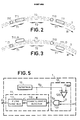
- FIG. 2 illustrates an exemplary embodiment among others of flags 71 defining the mean axis 70 of tracks 7 along which the information can be recorded. As has just been recalled, between two identical flags 71, there is an area 72 intended for recording useful information data. The direction of rotation of the disc has been represented in FIG. 2 by the arrow R.
- the track 7 shown in the figure is a virtual track, the mean axis 70 of which represents the ideal trajectory to be followed by a writing beam. It can however be materialized in certain applications by a groove, “smooth” before recording in the zones 72.
- the signals necessary for the radial control of the writing head will be derived from the detection of the flags 71 by means of tracking track which will be described in more detail in the following.
- a tracking signal can be generated in a conventional manner.
- the signal processing means must however memorize the measurement during the time interval elapsing between two successive flag passages in the area lit by the tracking light. According to the invention, the control signal can be deduced from the evolution of the signal measured at these two times.
- FIG. 2 illustrates one of these possibilities.
- Each flag 71 is divided into several sections 710, 711, the lengths and the spatial distribution of which define a code which makes it possible to identify a flag without ambiguity.
- each flag comprises, in addition to one or more possible sections centered on the mean axis of the runway and indicating the start of the flag, one or more other sections offset with respect to this mean axis.
- a first flag 71 comprises a section 710 centered on the mean axis of the track 70 and a second section 711-G offset to the left of this axis.
- the next flag 71 ' also includes a first section 710 centered on the middle axis 70 and a second section 711-D offset to the right of the axis. This succession is repeated.
- the difference between the offset sections and the axis 70 of the track is of the order of a fraction of the width of the tracking spot.
- each flag comprises at least one section shifted to the left and one section shifted to the right.
- the spatial distribution of the flags 71, 71 ′ is preferably uniform.
- the pre-etching elements 71 as well as the etching corresponding to the information recorded in the zones 72 take the form of disturbances in the heat-sensitive layer, in hollow or in bumps.
- Most often two levels are thus defined, one of which can be confused with the plane defined by the surface of the surface layer of the heat-sensitive material before any recording, that is to say also with the plane of the interpiste zones.
- One associates with these two levels one of the logical states "1" or "0 •.
- the invention takes advantage of this phenomenon.
- blank areas of any recording including pre-engraving in the form of grooves or smooth sections, are provided along the tracks.
- These areas must have a configuration such that the smallest of their dimensions is greater than the largest of the dimensions of the spot for exploring the tracks, this when the beam is focused in the plane of the surface of these areas.
- the step between two tracks that is to say the distance between tracks, must be greater than the dimension of the spot along this direction.
- the invention can be implemented according to two main embodiments which are themselves capable of several alternative embodiments.
- the blank areas can be interlaced with the etchings representing the information.
- the engraved patterns representing the information must preferably be of a surface much smaller than the surface of the exploration spot and leave sites between two successive engravings of length greater than this spot. The location of these sites can be systematically carried out between two positions reserved for engraving or on the contrary, the sites can be distributed in a more random manner.
- flags that is to say discrete pre-engraving elements synchronizing the start of the blank tracks intended for the sole purpose of generating a focusing signal.
- These flags must be selectively detectable. To do this, they can be associated with a specific code, for example consisting of a series of pre-etching sections whose respective dimensions and / or spatial distribution distinguish them from the codes associated with the other engraving elements, in particular the associated codes. to useful information data recorded.
- FIG. 4 illustrates an example of data recording whose configuration allows the implementation of a variant according to the first embodiment.
- a binary word with four bits of arbitrary configuration "1 0 1 1 is taken as an example.
- One category of code among others that can meet the above requirements is the pulse code.
- the logic states “1 are represented by a brief positive pulse which will result in an engraving element 720 of small dimension created along the track 7 and centered on the mean axis 70.
- the time interval T corresponds to the basic recording period of a binary or bit element, taking into account the speed of travel of the information medium.
- Logical states “0 translate into the absence of etching on the track and merge with the remaining tracks of the support, in particular the track tracks, this naturally if the track does not have a smooth pre-etched groove which constitutes one of the requirements to respect.
- the ranges 73 corresponding to the recording of the states logic “0 possibly overflowing on the two adjacent areas outside the etchings 720 can be used for the purposes of generating signals for controlling the focusing.
- FIG. 5 represents opto-electronic circuits making it possible to generate the vertical control signals ⁇ '. These circuits can be inserted into a system similar to that described in relation to FIG. 1 and are located in the control block bearing the reference 1 in this figure. Only the vertical control circuits are specific to the invention, the other circuits are common to the known art and do not require any particular description.
- This member which detects the radiation coming from the area illuminated by the spot 3 comprises at least one photodetector cell delivering an output signal V D transmitted to circuits 11 for processing the vertical servo error signal ⁇ 'and to sampling circuits 12.
- the latter have the role of generating operating authorization signals transmitted to circuits 11 centered on the time intervals corresponding to the logical state records "0", that is to say ranges track 7 without engraving larger than the exploration spot 3 ( Figure 4).
- the sampling circuits 12 comprise a member 120 for comparison with a threshold V REF .
- This last circuit can be constituted by an amplifier with differential inputs which receives on direct (+) and inversion inputs (-) respectively the signals V o and V REF and which delivers an output signal S, for example in the logic state "1", when the detected signal V o passes below a determined threshold.
- the signal S is transmitted to one of the inputs of an AND logic gate: 121.
- the other input receives impulse clock signals H centered on the middle of the periods T (Fig. 4). To do this, these clock signals can be derived from conventional so-called "bit" clock signals which are used in digital data recording / playback systems. These signals precisely define the base period T and synchronize the recording or reading of the data.
- an authorization signal SA is present on the output of the AND gate: 122.
- This signal SA defines a window analysis and authorizes the taking into account of the signal V o by the circuits for developing the error signal ⁇ 'within the time interval of the analysis window.
- a blocking sampler element 110 memorizing the signal V o between two samples taken, that is to say between the passages in the range illuminated by the spot d exploration 3 of two areas without etching as defined in the above.
- the output signal ⁇ ' N is then a staircase signal. To be usable, it must be “smoothed”, for example using a low-pass filter 111 delivering on its output the error signal ⁇ 'transmitted to the vertical control members of the objective O B , that is to say essentially at winding B.
- FIG. 6 illustrates a first alternative embodiment according to the second, preferred, embodiment of the invention.
- Sites made up of virgin beaches 73 are arranged along the tracks 7 and are associated with flags 74 which precede them. If the radial control is carried out using the detection of specific flags, these flags can be used in the context of the invention in place of the flags 74 and thus play a double role while avoiding the reduction of the recording density resulting from the recording of additional flags.
- the flags can be of all types and, without this being limiting, be produced for example according to any one of the main variant embodiments illustrated by FIGS. 2 and 3. The only constraint is that these flags must be selectively detectable between all the engraving configurations present on the disc.
- Figure 7 illustrates a second preferred embodiment of the same embodiment.
- the disc is sectorized and all the tracks 73, as well as the associated flags 74, are aligned on a radial axis ⁇ R passing through the center of rotation of the disc 5.
- ⁇ R passing through the center of rotation of the disc 5.
- only five concentric tracks 7 have been represented.
- all the blank areas 73 are combined into a single area having the shape of a right-angled quadrilateral whose largest dimension is parallel to the axis A R.
- a disc 30 cm in diameter comprises around 40,000 tracks distributed in a crown with a width of 8 cm or useful recording area. Each track has around 3,500 blank beaches and as many associated flags.
- This arrangement has the advantage of allowing a smaller inter-track step, that is to say a higher recording density. Indeed, the exploration spot 3 can overflow onto an adjacent track without the risk of intercepting an etching element of this track. Focusing is then made entirely independent of radial tracking errors.
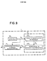
- FIG. 8 represents an example of circuits for processing the signal E 'adapted to the preferred embodiment of the invention.
- these circuits include a flag identification circuit 122, for example a logic decoder recognizing the specific code associated with the flags 74 preceding the blank areas 73 and delivering an initialization signal S c , for example pulse, of a generator 123 of the authorization signal SA.
- a flag identification circuit 122 for example a logic decoder recognizing the specific code associated with the flags 74 preceding the blank areas 73 and delivering an initialization signal S c , for example pulse, of a generator 123 of the authorization signal SA.
- This can advantageously be based on monostable flip-flops initialized by one of the transitions of the signal S c and delivering an output signal defining an analysis window of duration 6 and sufficiently delayed so that, given the speed of movement tracks in the area lit by the exploration spot 3, this is centered on the blank area 73 at the time when the authorization signal SA is generated and, correlatively, the measurement taken into account by the sampler blocker 110.
- the process which has just been described in its two main embodiments is compatible with all the tracking methods and information reading.
- it can be implemented in a single-track-mono-beam system.
- the single beam is used for writing, to ensure radial tracking preferably using the flags 74 and for generating the vertical servo signal e 'according to the teaching of the invention.
- the opto-electronic members implemented in these methods can also be used to generate the signal V D.
- Detection can be carried out according to many known methods.
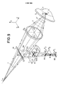
- an asymmetrical type of implementation device can be used according to the teaching of the French patent FR-B-2 325 953 or an astigmatic type according to the teaching of the French patent FR-B-2 271 590.
- FIG. 9 shows a radiated energy source L a emitting a beam f along the axis OZ of an orthonormal reference frame OXYZ; means M for separating the radiated energy, such as a semi-transparent mirror, making with the axis OZ an angle of ⁇ / 4 radians for example; an objective O b with an optical axis Ox, causing the beam f to converge in a spot 3 on the support 5.
- the source L a can be considered to be punctual. It is for example the emissive face of a laser diode.
- At least a fraction of the beam f is reflected by the support 5: this reflected beam crosses the objective O b then is reflected by the semi-transparent mirror M to converge at a point A, symmetrical with the source L a with respect to the mirror M, located on an axis ⁇ x parallel to OX; through point A passes a plane normal to the axis ⁇ x marked P 1 .
- An optical device C is interposed on the axis ⁇ x , making it possible to make the optical assembly placed on the path of the reflected beam f astigmatic; such a device can be produced using a cylindrical lens, the axis of the cylinder being for example chosen parallel to the axis OZ.
- the cylindrical lens C has the effect of making the point source La correspond to a straight line 80, on either side of the point A in the plane P 1 , parallel to the axis OY in the example shown in the figure.
- the lines 82 and 83 which are substantially circular, of the reflected beam f ′, on the mirror M and on the cylindrical lens C, as well as the diameters 830 and 831 have been shown diagrammatically in the drawing;
- the rays 85 define the segment 81 after convergence at a point A 'of the axis ⁇ x in the plane P 2 ; the rays converge at point A.
- the plane P 0 is located on the axis ⁇ x between the points A and A 'where the surface of the spot 8 is minimal; the plane P o is orthogonal to the axis ⁇ x .
- a focused spot deformed with respect to spot 8 is formed on the plane P o by elongation in directions parallel to the axes OY and OZ depending on whether the beam converges in front or behind the surface of disc reference 5, that is to say in the context of the invention of the surface of the blank pads 73.
- means for detecting the shape of the focused spot are placed, these means being for example produced using photoelectric cells as illustrated in FIG. 10, delivering a control signal of focus.
- the detection means in this embodiment include four photoelectric cells D 1 , D 2 , D 3 , D 4 , placed in a square whose diagonals are parallel to the axes OY and OZ, and placed so that the focused spot 8 forms substantially in the middle of the square.
- the cells belonging to the same diagonal are connected to the inputs of an adder; that is to say in FIG. 10, cells D 1 and D 2 on the diagonal parallel to the axis OY, at the inputs of the adder 35 and cells D 3 and D 4 , on the other diagonal , at the inputs of an adder 36.
- the adders are connected to a differential amplifier 37: the adder 35 at the positive input of the amplifier and the adder 36 at its negative input. At the output of amplifier 37 is available the electrical signal V D which constitutes the focus control signal.
- the three formed by focusing spots capable of forming in the observation plane P o are represented in FIG. 10: the contour 8, of minimum surface, mentioned above; a contour 801 elongated along the axis OY, and a contour 802 elongated along the axis OZ.
- the signal V D is zero when the focusing is correct (spot 8, substantially circular), positive when the surface of the pads 73 has moved away from the objective O b (spot 801) and negative when the surface of the pads 73 has approached the objective O b (spot 802).
- the signal V D is representative of the focusing error of the beam f, in amplitude and in sign.
- the signal V D is sampled during the analysis windows and stored between two samples by the devices which have been described in relation to FIGS. 5 and 8.
- the diagram of FIG. 11 illustrates an example of evolution of the vertical servo error signal ⁇ 'as a function of time.
- the curve in the upper part of the diagram represents the position 8 z along an axis of vertical coordinate of the exploration spot 3 relative to the reference plane, of zero altitude, consisting of the surface of the blank areas 73.
- the curve e 'on the lower part of the diagram schematically represents the corresponding evolution as a function of time of the smoothed focusing error signal e'.
- the analysis windows corresponding to the passages of the blank areas in the area illuminated by the exploration spot 3 are represented in a simplified manner as the blank areas by points marked 0 1 to 6 9 .
- On the same diagram is represented the curve in steps of staircase of the signal F-'N as memorized between each passage of the blank areas 73.
- the time interval elapsing between two analysis windows depends on the rotation speed of the disc and the length of the zones 72.
- the second method of the type described in the aforementioned first French patent consists, after having introduced an asymmetry in the scanning beam, in forming the image of the focusing spot on photoelectric cells in at least equal number to two, and to measure the distortions of this image.
- the signals delivered by the photoelectric cells are a function of the difference existing between the focusing plane and the reference plane formed in the context of the present invention by the surface of the blank areas.
- the loop of the focusing servo-control circuits is open and a sawtooth signal is transmitted to one of the solenoids which are provided with the means for servo-control of the vertical position of the objective O b , for example the solenoid B in FIG. 1 or an additional solenoid specific for this use.
- the objective will therefore move from a rest position to a position for which the focusing spot will be in a plane close to the reference plane as it has been defined.
- the flag identification circuits 122 of the device described in relation to the FIG. 8 will start to produce control signals S c , the instant of appearance of which can be used to generate a signal for closing the vertical servo loop.
- the spot is then located in a plane sufficiently close to the reference surface so that the vertical control circuits can "catch on this surface.
- the value of the amplitude of the signal V D can be used compared with a reference threshold for generate a vertical servo loop closure signal.
- the invention is not limited to the only exemplary embodiments which have been described and in particular only to the devices for implementing the method described in relation to FIGS. 5 and 8.
Claims (10)
Applications Claiming Priority (2)
| Application Number | Priority Date | Filing Date | Title |
|---|---|---|---|
| FR8210407 | 1982-06-15 | ||
| FR8210407A FR2528605B1 (fr) | 1982-06-15 | 1982-06-15 | Procede et dispositif optique de focalisation d'un faisceau d'energie lumineuse sur un plan de reference d'un support d'information ainsi que ce support |
Publications (2)
| Publication Number | Publication Date |
|---|---|
| EP0097092A1 EP0097092A1 (de) | 1983-12-28 |
| EP0097092B1 true EP0097092B1 (de) | 1986-12-03 |
Family
ID=9275017
Family Applications (1)
| Application Number | Title | Priority Date | Filing Date |
|---|---|---|---|
| EP83401155A Expired EP0097092B1 (de) | 1982-06-15 | 1983-06-07 | Verfahren und optisches Gerät zum Fokussieren eines Lichtstrahlbündels auf eine Bezugsebene eines Informationenträgers |
Country Status (8)
| Country | Link |
|---|---|
| US (2) | US4561082A (de) |
| EP (1) | EP0097092B1 (de) |
| JP (1) | JPH07101515B2 (de) |
| CA (1) | CA1203620A (de) |
| DE (1) | DE3368140D1 (de) |
| FR (1) | FR2528605B1 (de) |
| HK (1) | HK16790A (de) |
| SG (1) | SG66989G (de) |
Families Citing this family (36)
| Publication number | Priority date | Publication date | Assignee | Title |
|---|---|---|---|---|
| JPS6077053A (ja) * | 1983-10-03 | 1985-05-01 | Kureha Chem Ind Co Ltd | 原反位置調整装置 |
| NL8303564A (nl) * | 1983-10-17 | 1985-05-17 | Philips Nv | Inrichting voor het weergeven van informatie van een optisch uitleesbare registratiedrager. |
| JPS60129935A (ja) * | 1983-12-16 | 1985-07-11 | Canon Inc | 光学的情報処理装置 |
| JPS61170934A (ja) * | 1985-01-25 | 1986-08-01 | Hitachi Ltd | 光デイスク記録装置 |
| CA1258909A (en) * | 1985-03-29 | 1989-08-29 | Hideki Hosoya | Optical information recording medium and method for recording information on said medium and reproducing information therefrom |
| FR2584223B1 (fr) * | 1985-06-28 | 1994-06-17 | Thomson Alcatel Gigadisc | Memoire optique a suivi de piste echantillonne pour support d'information pregrave. |
| DE3687495T2 (de) * | 1985-07-30 | 1993-07-29 | Philips Nv | Generatorkreis fuer spursignal und aufzeichnungstraeger dafuer. |
| US4879707A (en) * | 1985-07-30 | 1989-11-07 | Laser Magnetic Storage International Company | Optical disk tracking and seeking systems specific track formats using discontinuities |
| US4879708A (en) * | 1985-07-30 | 1989-11-07 | Laser Magnetic Storage International Company | Optical disk tracking and seeking systems specific track formats using wobbled pits |
| US4959823A (en) * | 1985-07-30 | 1990-09-25 | Laser Magnetic Storage International Company | Tracking and seeking system for use with an optical record carrier having a wobbled track format |
| EP0220023B1 (de) * | 1985-10-08 | 1993-07-07 | Sharp Kabushiki Kaisha | Magnetooptische Speichervorrichtung |
| FR2597248B1 (fr) * | 1985-11-27 | 1988-05-13 | Thomson Alcatel Gigadisc | Support d'information a pregravure et son dispositif d'exploration optiques a acces echantillonne |
| US5173886A (en) * | 1986-02-07 | 1992-12-22 | Matsushita Electric Industrial Co., Ltd. | Composite optical disc having both a data read-only area and a data rewritable area, and a recording/reproducing system for use therewith |
| DE3750409T2 (de) * | 1986-02-07 | 1995-03-30 | Matsushita Electric Ind Co Ltd | Optische Platte und Plattengerät zum Aufzeichnen oder Wiedergeben von Daten in oder von der Platte. |
| NL8600934A (nl) * | 1986-04-14 | 1987-11-02 | Optical Storage Int | Optische registratiedrager en inrichting voor het uitlezen van de registratiedrager. |
| WO1988001785A1 (en) * | 1986-08-25 | 1988-03-10 | Sony Corporation | A disc device and a disc-like recording medium |
| US4819218A (en) * | 1986-12-19 | 1989-04-04 | Eastman Kodak Company | Quasi-constant linear-velocity disk having corresponding radii of adjacent annular zones related by a rational number for distributing prerecorded indicia to form a coherent write clock signal |
| US4949325A (en) * | 1987-03-18 | 1990-08-14 | Hitachi, Ltd. | Method and associated apparatus and medium for optical recording and reproducing information |
| JPS63237269A (ja) * | 1987-03-25 | 1988-10-03 | Sony Corp | トラツクカウント装置 |
| JPH0719385B2 (ja) * | 1987-04-24 | 1995-03-06 | 株式会社日立製作所 | 光学的記録再生装置 |
| US4982392A (en) * | 1987-07-10 | 1991-01-01 | Ricoh Company, Ltd. | Stabilized optical pick-up device inhibiting the effect of the focus error signal at the start and end of a data region |
| JPS6446240A (en) * | 1987-08-14 | 1989-02-20 | Toshiba Corp | Disk device |
| DE3884354T2 (de) * | 1987-11-30 | 1994-01-20 | Toshiba Kawasaki Kk | Gerät zum Fokussieren eines Lichtstrahls auf einem Informationsspeichermedium. |
| JP2735220B2 (ja) * | 1987-12-02 | 1998-04-02 | 株式会社日立製作所 | 非点収差を有する光束を用いた焦点ずれ検出方法及び光ディスク装置 |
| JPH073692B2 (ja) * | 1987-12-02 | 1995-01-18 | 株式会社日立製作所 | 光ディスク装置におけるトラッキング制御回路 |
| NL8702904A (nl) * | 1987-12-03 | 1989-07-03 | Philips Nv | Werkwijze en inrichting voor het optekenen van informatie op een registratiedrager, alsmede een inrichting voor het lezen van de opgetekende informatie. |
| US4847824A (en) * | 1987-12-21 | 1989-07-11 | International Business Machines Corporation | Readback circuits for magnetooptic players |
| US5031166A (en) * | 1988-01-25 | 1991-07-09 | Laser Magnetic Storage International Company | Optical disk tracking and seeking systems and specific track formats using discontinuities and circuitry therefor |
| US5006703A (en) * | 1988-02-22 | 1991-04-09 | Victor Company Of Japan, Ltd. | Reflective optical rotary encoder disc |
| JP2669532B2 (ja) * | 1988-05-20 | 1997-10-29 | 株式会社日立製作所 | 光ディスク装置 |
| JPH0646487B2 (ja) * | 1989-03-31 | 1994-06-15 | キヤノン株式会社 | 情報記録再生方法、情報記録再生装置及び情報記録担体 |
| US5185730A (en) * | 1989-06-01 | 1993-02-09 | Pioneer Electronic Corporation | Method for reading data from optical disk |
| US5148422A (en) * | 1989-08-25 | 1992-09-15 | Sony Corporation | Optical recording medium having a data recording track with offset data storing regions |
| FR2685518B1 (fr) * | 1991-12-23 | 1994-02-04 | Thomson Csf | Circuit d'horloge pour systeme de lecture d'informations sequentielles. |
| TW491996B (en) * | 1999-11-04 | 2002-06-21 | Koninkl Philips Electronics Nv | Device for reading and/or writing information from/onto an optical information carrier |
| US20090028021A1 (en) * | 2004-06-01 | 2009-01-29 | Koninklijke Philips Electronics, N.V. | Radial To Focus Cross Talk Cancellation In Optical Storage Systems |
Family Cites Families (13)
| Publication number | Priority date | Publication date | Assignee | Title |
|---|---|---|---|---|
| FR2311326A2 (fr) * | 1974-01-15 | 1976-12-10 | Thomson Brandt | Dispositif de focalisation et lecteur optique comportant un tel dispositif |
| US3919697A (en) * | 1974-06-26 | 1975-11-11 | Battelle Development Corp | Data record tracking using track identifying information in the gaps between recorded data groups |
| US4094013A (en) * | 1975-05-22 | 1978-06-06 | U.S. Philips Corporation | Optical storage disk system with disk track guide sectors |
| JPS55117743A (en) * | 1979-02-28 | 1980-09-10 | Toshiba Corp | Automatic focusing system |
| US4290122A (en) * | 1979-05-14 | 1981-09-15 | Xerox Corporation | Self-synchronizing clock source for optical memories |
| JPS5637A (en) * | 1979-06-11 | 1981-01-06 | Hitachi Ltd | Tracking system of optical disc memory |
| NL7906576A (nl) * | 1979-09-03 | 1981-03-05 | Philips Nv | Registratiedrager waarin informatie is aangebracht in een optisch uitleesbare informatiestruktuur, alsmede uitleesinrichting daarvoor. |
| JPS5774837A (en) * | 1980-10-25 | 1982-05-11 | Olympus Optical Co Ltd | Signal detection system of optical information reproducing device |
| US4443870A (en) * | 1981-10-15 | 1984-04-17 | Burroughs Corporation | Optical memory system providing track following |
| US4402061A (en) * | 1981-10-15 | 1983-08-30 | Burroughs Corporation | Preformatted optical media for use in an optical memory system |
| US4428075A (en) * | 1981-12-21 | 1984-01-24 | Burroughs Corporation | Methods of preformatting an optical disk |
| FR2523349A1 (fr) * | 1982-03-12 | 1983-09-16 | Thomson Csf | Procede et dispositif optique de generation de signaux d'asservissements de la position d'une tache d'exploration des pistes d'un support d'information |
| FR2523347B1 (fr) * | 1982-03-12 | 1988-11-04 | Thomson Csf | Support d'information mobile pregrave et dispositif optique de suivi de piste mettant en oeuvre un tel support |
-
1982
- 1982-06-15 FR FR8210407A patent/FR2528605B1/fr not_active Expired
-
1983
- 1983-06-07 EP EP83401155A patent/EP0097092B1/de not_active Expired
- 1983-06-07 DE DE8383401155T patent/DE3368140D1/de not_active Expired
- 1983-06-13 US US06/503,655 patent/US4561082A/en not_active Expired - Lifetime
- 1983-06-13 CA CA000430304A patent/CA1203620A/en not_active Expired
- 1983-06-14 JP JP58106590A patent/JPH07101515B2/ja not_active Expired - Lifetime
-
1985
- 1985-08-30 US US06/771,269 patent/US4669077A/en not_active Expired - Lifetime
-
1989
- 1989-09-30 SG SG669/89A patent/SG66989G/en unknown
-
1990
- 1990-03-01 HK HK167/90A patent/HK16790A/xx not_active IP Right Cessation
Non-Patent Citations (1)
| Title |
|---|
| NEUES AUS DER TECHNIK, no. 5, 15 octobre 1979, Seiten 1-2, Vogel-Verlag, Würzburg, DE. Article 542: "Synchronisation des Datenbitstromes bei Aufzeichnung auf einem scheibenförmigen Aufzeichnungsträger" * |
Also Published As
| Publication number | Publication date |
|---|---|
| EP0097092A1 (de) | 1983-12-28 |
| FR2528605B1 (fr) | 1987-11-20 |
| CA1203620A (en) | 1986-04-22 |
| JPS593728A (ja) | 1984-01-10 |
| JPH07101515B2 (ja) | 1995-11-01 |
| US4561082A (en) | 1985-12-24 |
| HK16790A (en) | 1990-03-09 |
| SG66989G (en) | 1990-03-09 |
| US4669077A (en) | 1987-05-26 |
| FR2528605A1 (fr) | 1983-12-16 |
| DE3368140D1 (en) | 1987-01-15 |
Similar Documents
| Publication | Publication Date | Title |
|---|---|---|
| EP0097092B1 (de) | Verfahren und optisches Gerät zum Fokussieren eines Lichtstrahlbündels auf eine Bezugsebene eines Informationenträgers | |
| EP0369989B1 (de) | Vorgeprägter beweglicher Informationsträger und optische Spurfolgeanordnung dafür | |
| EP0089274B1 (de) | Optischer Informationsträger, optische Anordnung zur Spurfolge und optische Anordnung zur Erzeugung eines Fehlersignals zur Scharfeinstellung | |
| EP0126682B1 (de) | Verfahren und Vorrichtung zur Festlegung der für Datenaufnahme auf eine optische Scheibe aufgebrachten optischen Leistung | |
| EP0201093B1 (de) | Vorgravierter Informationsträger und optische Lesevorrichtung dafür | |
| EP0064897B1 (de) | Informationsträgerplatte mit Winkelkodierung und Rotationsantriebsvorrichtung für eine solche Platte | |
| EP0012650A1 (de) | Vorrichtung mit Zugriff zu einer Spur eines optisch registrierbaren oder lesbaren Trägers und eine solche Vorrichtung enthaltendes optisches System | |
| EP0090690B1 (de) | Verfahren und Anordnung zur Regenerierung der Phase der Synchronisationssignale in einem optischen Aufzeichnungswiedergabegerät für Informationsträger | |
| FR2508218A1 (fr) | Disque optique et appareil a disque optique destine a l'utiliser | |
| FR2619241A1 (fr) | Procede et dispositif de controle de la mise au point, notamment pour le lecteur de disque optique numerique | |
| FR2505536A1 (fr) | Appareil de lecture d'informations optiques notamment sur un disque | |
| EP0072723B1 (de) | Optische Anordnung zur Spurhaltung mittels Stichprobenauswertung | |
| EP0169433B1 (de) | Informationsträger zur optischen Aufzeichnung entlang einer Spur vorgeprägter Marken und eine Spurverfolgungsanordnung dafür | |
| EP0811227A1 (de) | Träger für optische informationsaufzeichnung/-wiedergabe und aufzeichnungsverfahren | |
| EP0022682A1 (de) | Optischer Lesekopf mit Halbleiter-Laserquelle und eine mit optischer Reflexion arbeitende Lesevorrichtung zum Lesen eines Informationsträgers, die einen solchen optischen Lesekopf enthält | |
| FR2575857A1 (fr) | Appareil de stockage optique d'informations | |
| CH665043A5 (fr) | Appareil d'enregistrement et de reproduction d'informations optiques. | |
| KR20000057116A (ko) | 광 디스크 매체, 광 디스크 시스템 및 광 디스크의 방사방향 기울어짐 측정 방법 | |
| EP0789907B1 (de) | Fokussierungssteuersystem | |
| FR2504301A1 (fr) | Support d'informations mobile et dispositif d'enregistrement-lecture comprenant un tel support | |
| EP0064438A1 (de) | Aufzeichnungs-/Wiedergabeanordnung, die einen beweglichen Informationsträger mit einer vorgeprägten Spur enthält | |
| FR2613865A1 (fr) | Support d'information mobile pregrave et dispositif optique de suivi de piste mettant en oeuvre un tel support |
Legal Events
| Date | Code | Title | Description |
|---|---|---|---|
| PUAI | Public reference made under article 153(3) epc to a published international application that has entered the european phase |
Free format text: ORIGINAL CODE: 0009012 |
|
| AK | Designated contracting states |
Designated state(s): DE GB IT NL SE |
|
| 17P | Request for examination filed |
Effective date: 19840109 |
|
| GRAA | (expected) grant |
Free format text: ORIGINAL CODE: 0009210 |
|
| AK | Designated contracting states |
Kind code of ref document: B1 Designated state(s): DE GB IT NL SE |
|
| REF | Corresponds to: |
Ref document number: 3368140 Country of ref document: DE Date of ref document: 19870115 |
|
| ITF | It: translation for a ep patent filed |
Owner name: JACOBACCI & PERANI S.P.A. |
|
| PLBE | No opposition filed within time limit |
Free format text: ORIGINAL CODE: 0009261 |
|
| STAA | Information on the status of an ep patent application or granted ep patent |
Free format text: STATUS: NO OPPOSITION FILED WITHIN TIME LIMIT |
|
| 26N | No opposition filed | ||
| ITTA | It: last paid annual fee | ||
| EAL | Se: european patent in force in sweden |
Ref document number: 83401155.3 |
|
| REG | Reference to a national code |
Ref country code: GB Ref legal event code: IF02 |
|
| PGFP | Annual fee paid to national office [announced via postgrant information from national office to epo] |
Ref country code: DE Payment date: 20020521 Year of fee payment: 20 |
|
| PGFP | Annual fee paid to national office [announced via postgrant information from national office to epo] |
Ref country code: SE Payment date: 20020522 Year of fee payment: 20 Ref country code: GB Payment date: 20020522 Year of fee payment: 20 |
|
| PGFP | Annual fee paid to national office [announced via postgrant information from national office to epo] |
Ref country code: NL Payment date: 20020531 Year of fee payment: 20 |
|
| PG25 | Lapsed in a contracting state [announced via postgrant information from national office to epo] |
Ref country code: GB Free format text: LAPSE BECAUSE OF EXPIRATION OF PROTECTION Effective date: 20030606 |
|
| PG25 | Lapsed in a contracting state [announced via postgrant information from national office to epo] |
Ref country code: NL Free format text: LAPSE BECAUSE OF EXPIRATION OF PROTECTION Effective date: 20030607 |
|
| REG | Reference to a national code |
Ref country code: GB Ref legal event code: PE20 |
|
| EUG | Se: european patent has lapsed | ||
| NLV7 | Nl: ceased due to reaching the maximum lifetime of a patent |
Effective date: 20030607 |